Thanks again for your responses. I tried using your values in VCAD as suggested by Don. Both Don's and Shadow's traces for the freq response came out differently although the impedance traces seem similar. Either I am making a big mistake or the software calculates results differently. Which one is correct or what am I doing wrong in VCAD.
Don, I haven't decided on the layout of the drivers in the box, MTMWW or WMTMW, that is mt next problem. I would like to use VCAD because it has a box designer.
Don, I haven't decided on the layout of the drivers in the box, MTMWW or WMTMW, that is mt next problem. I would like to use VCAD because it has a box designer.
Attachments
Xsim is not inaccurate. The results should be the same for Vcad and Xsim provided the data and usage is the same.

@alpha32 That is good news.
The factory driver data (FRD, ZMA) was measured, on driver axis, using something like an IEC 286-5 test baffle. This is appropriate for a driver spec.
Xsim does not have ability to position the drivers. It relies on you providing the measured data from your box at your measuring position. An accurate SPL graph would require you to build a test box, then measure each driver separately at a fixed measuring position, then import that data (FRD) into Xsim. The impedance calculated by Xsim does not require driver placement, that's why only impedance matches VCAD impedance when factory driver data is used.
The XO relative electrical phase, and the driver relative positions, and the box/baffle shape will effect the SPL at the measured position. So small tweaks in the XO, or driver position may not effect the impedance, but they will effect the SPL output. The VCAD model will include these factors and be more accurate with less work.
Last edited:
Xsim allows you to separately set the delay. No other positioning is needed.. unless you're doing a 3D crossover.
Vcad positioning does not affect impedance or baffle diffraction. It is used for external purposes such as timing and polars.
Vcad positioning does not affect impedance or baffle diffraction. It is used for external purposes such as timing and polars.
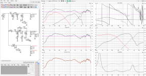
VituixCad vs. XSim (green line)Thanks again for your responses. I tried using your values in VCAD as suggested by Don. Both Don's and Shadow's traces for the freq response came out differently although the impedance traces seem similar. Either I am making a big mistake or the software calculates results differently. Which one is correct or what am I doing wrong in VCAD.
Don, I haven't decided on the layout of the drivers in the box, MTMWW or WMTMW, that is mt next problem. I would like to use VCAD because it has a box designer.
Differences are negligible, you have to use the frd/zma files located in the directory created when you open the project I attached above.
It's a WWMTM / 24L BR tuned at 40Hz.
OK, I think I have decided on an XO and the drivers. Now for the box. I tried DIY audio, Winisd and Vcad to calculate the bos and port sizes. Winisd does not have a facility where I can specify two drivers in parallel so I doubled the Vas and adjusted the effective cone diameter using the Sd value. The results are below. Some results are close but others vary a lot. Also I don't understand how the mid has a larger box than the woofer. Any comments would be appreciated.
Thanks
Thanks
Port | ||||
| DC160-4 | Box | Dia | Length | Fb |
| Diy Audio | 37.03 | 5 | 8.26 | 36.53 |
| WinIsd | 40.35 | 5 | 7.9 | 35.91 |
| VituixCAD | 24.8 | 5 | 11.1 | 39 |
| ND140-4 | ||||
| Diy Audio | 62.87 | 5 | 2.63 | 37.52 |
| WinIsd | 64.84 | 5 | 5.25 | 38.39 |
| VituixCAD | 27.3 | 5 | 1.8 | 59.2 |
Seems about right but why are you porting the mids? Those specs are different because of the alignments. They must be using different ones. The ND140 likes a big box, even if it is a closed box.
You have choosen a different alignment - B4 in Vcad and QB3 in WinISD - so you get different results for Vb and Fb, besides the port length depends on Vb and Diam.OK, I think I have decided on an XO and the drivers. Now for the box. I tried DIY audio, Winisd and Vcad to calculate the bos and port sizes. Winisd does not have a facility where I can specify two drivers in parallel so I doubled the Vas and adjusted the effective cone diameter using the Sd value. The results are below. Some results are close but others vary a lot. Also I don't understand how the mid has a larger box than the woofer. Any comments would be appreciated.
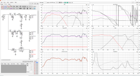
A 25L BR box with stuffing on the wall would be fine. The brown line includes the baffle step.
A 15L closed box (with full stuffing) for both mids would be OK. The volume is a bit high as the Qts of the mid is high, maybe you could consider other mid to decrease the box volume.
PS if you do not have a measurement mic consider to buy one in order to have accurate results.
The midrange needs something more "fullrange" and less "woofer" than a ND140. Something like a DS90 or RS75 are similar price but have smaller Vas numbers and a smaller rear chamber (closed box). A small midrange chamber is better for reducing internal reflections and resonances. Most box calculators will not show these (except Hornresp and Akabak BEM sims).
Last edited:
OK, I have changed the mid. The box sizes do seem more realistic. I haven't designed the box yet so not sure whether the mid will be ported. The frequency response is good until the mid/tweeter XO (I don't think my old ears will notice) and the impedance is good. Are there any more suggestions? Xsim file is attached. Thanks
Attachments
Your mid-tw filter is a mess. Why do you need woofers' voltage divider?
Is your cabinet baffle slanted or straight up?
Is your cabinet baffle slanted or straight up?
The woofer zma file in your project is that of a driver measured in free air and not in a vented box, also its frd doesn't include the baffle step loss. As the woofer configuration is the same you could use the xsim file I attached above as a starting point. Consider to apply baffle step to the mid too.
This mid is much more linear at high frequency
https://www.daytonaudio.com/images/resources/295-359--dayton-audio-rs100p-8-specifications.pdf
This mid is much more linear at high frequency
https://www.daytonaudio.com/images/resources/295-359--dayton-audio-rs100p-8-specifications.pdf
Yes, I am still trying for improvement. I thought my last effort was OK, 6 ohm impedance and flat response (until the tweeter) but you called it a mess! I am away from home for a few days. I have added the notches, BSC and zebel.
Could you brief me on information about the baffle size, drive units position, complete data I might
use to try a brand new sim. I'll find some time to brew a simple and effective filter. I'll include baffle
step.
use to try a brand new sim. I'll find some time to brew a simple and effective filter. I'll include baffle
step.
Thanks Lojzek, at this stage the baffle will be 200mm wide and the config mtmww. I thought wmtmw would be nice but seems more problematic. I won't have more info until I get back home.
Using DIY Audio & video's calculator for the box design I get 37L for the woofers and 11L for the mids. This gives a box height of 750mm and depth of 300mm for the woofers and 200 high and 200 deep for the mids. Vents 50mm x 79mm for the woofers and 25mm x 16mm for the mids. I will round off the edges at 10mm. I don't know whether the grill will be recessed or stand off by 10mm with beveled edges. Is there any other data you need?
Thanks
Thanks
Midrange is high passed in a setup like this, and the bass gets help from woofer vents. Mid vents are a no go.
There is also better and cheaper Dayton drivers for the mids duties than the ND 140-8, with better behaved cone material, smoother which comes handy designing a lower order filter.
There is also better and cheaper Dayton drivers for the mids duties than the ND 140-8, with better behaved cone material, smoother which comes handy designing a lower order filter.
37L @37Hz Vs. 24L @39Hz (dashed blue lines). The brown line is considering the baffle step loss for a panel width of 22cm.
You loose a bit of bass extension (37Hz vs. 48Hz), but cabinet is smaller, transient and group delay are better.
Agree with Lojzek, the vented box for a mid is an unnecessary complication, also transient are better in closed box.

You loose a bit of bass extension (37Hz vs. 48Hz), but cabinet is smaller, transient and group delay are better.
Agree with Lojzek, the vented box for a mid is an unnecessary complication, also transient are better in closed box.
Is there any other data you need?
Thanks
It's fine. Don't worry about it. I'll wait some more for you to consider my suggestion on different mids.
- Home
- Loudspeakers
- Multi-Way
- Correction of impedance in 3 way with Xsim