Cyrus III phono stage problem

Hi,
I recently bought a second hand Cyrus III with PSX-R which works okay on all inputs except the phono. I only get sound from the left channel when I connect my turntable. The same turntable and cables work fine into another amp.
I've cleaned the input sockets but still no right channel output.
Any ideas what could be causing this and any other tips for trying to fix the problem would be gratefully received.
Mark.

New member

Hello everyone,

My name is Vincent. I really like listening to music on my self build speakers. I have build a 2 way bluetooth speaker with a b&c de 250 and a Dayton Audio RS270p-4a. I also build a 3 way speaker pair that I currently use as my pc speakers. I do want to replace the 3 way speakers in the future with a 3 way speaker with compression drivers, since I do love the dynamics they can deliver.

Thermal interface, Pad vs. Paste, What to choose for large surface area?

The MeanWell UHP-500R-48 power supply is passively cooled through coupling with the chassis it is mounted in.

I could use thermal paste, but it can be messy and hard to apply in a thin even layer over a large surface, I am leaning towards using a large thermal pad.

The thermal pad should be ~232mm x 81mm for the power supply,

1729357183607.png


And I am going to need one for the amplifier board heat sink to couple it to the chassis heat sink, 3e Audio TPA3255 TPA3251 480-1-29A, 120mm x 85mm,

1729357311223.png


Suggestions on what brand and series thermal pad would be a good choice?

Thank you, David.

Transforming T-line to Bass reflex

About 9-10 years ago I build a 2-way T-line speaker set. They are a quite bad design, but I did put a lot of effort into building a nice looking, stiff and heavy box.
I did some calculations for the bass-mid driver and if I had a bass reflex with the same volume of box, the result should be really quite good.

There are a few things I am wondering about and would like your thoughts on.

1. If I simply close the end of the T-line, and put a vent there instead, will the enclosure behave like a bass reflex? Or will it behave differently. The cross section of the T-line is about 250cm2, which is much much bigger than any vent cross section. The total volume of the box is about 90 litres.

2. Would the placement of the vent matter? It will be most easy for me to add it to the new piece of wood I will close the end of the T-line with, but I could make a hole in another section if that would be a better choice.

3. For the ideal tuning of the box, the first harmonic of my vent will be at around 1kHz, while the crossover is a 4th order butterworth at 1.5kHz. I can't really find what happens if I were to implement that design. I assume it is not great, but I would like to confirm that before I make the bass extension (slightly) worse by tuning the box a little higher with a shorter port. I am already minimizing the diameter of the port while keeping air speed in check at the maximum volume level I intend to actually use.

Thanks for your input.

Thoughts on the B&C DCX354 Coaxial compression driver for hifi use?

Hi,

I am tinkering with different designs for a 3 way hifi speaker I would like to build in the future. I was considering a B&C DCX354 to use with the FaitalPRO LTH142. I have the following questions:
  • If you heard the B&C DCX354 what did you think of the sound?
  • What are your thoughts of using a coaxial compression driver compared to two seperated compression drivers for the mids and highs?
I did found a test bench article from AudioExpress. The results show a very high distortion figure of 12% around 4.8 kHz and the frequency response is not really smooth. This makes me wonder if a single 1.4 inch compression driver with a smoother response will be a better option than the DCX354.

Reasons for my interest in this driver:
  • One point of sound for the mids and highs
  • Smaller build volume by only using one horn
  • The mid and high of the coaxial compression drivers are likely tonal matched
  • Not too expensive

Hum and Buzz After Power Surges

On Thursday I had a power surge and I’m now thinking it may have caused issues in my main system where I now have buzz on every amp I try.

My original setup was - Gold Note Dac/streamer -> Academy Audio Volume control -> BBA3 front end preamp -> F4 monoblocks -> Magnepan LRS+ (fully balanced system)

I switched my system before I noticed the hum where I put an Aleph JZM right after the Academy Audio into some Zu speakers (fully balanced). I kept having buzzing on the left channel. I swapped the Aleph JZM for an F5 (using rca out from the Academy Audio) and same issue. I then tried an M2x with the same results but louder buzzing in both channels.

I tried removing the Academy Audio and went straight from my Gold Note as a preamp to the Aleph JZM but still have buzzing but in both channels.

I tried XLR and RCA shorting plugs on each amp and all of them are silent. I took the Aleph JZM and F5 into my office system and both of them were perfectly quiet there.

I also tried plugging in a different source to rule out the Gold Note and had the same noise.

The only way I am able to get a completely quiet system is to go

Gold Note Dac/streamer -> BBA3 front end preamp -> F4 monoblocks -> Zu Audio Unions (all balanced)
Adding the Academy Audio preamp back in caused buzzing and noise on just the left channel.

I unplugged my whole system hoping maybe it needs a reset. Going to try that after a few hours of rest.

Any other recommendations to check after a power surge?

Headphones driver: OPA1622 vs OPA1688

I'm planning to build this minimal circuit. The source is an I-out DAC. One opamp creates a virtual ground–strong enough for 32ohm HPs to sit on, the other a DAC filter+driver for the headphones.

The main candidate has been the OPA1622 so far, for its large output current. Then I discovered the OPA1688, weaker but maybe enough for me and easy to solder. Also good with capacitive loads. Simulating both I found something puzzling...

Crucial here is that DC offset is extremely low I guess, since headphones are DC coupled. On paper the OPA1622 has 0.1mV VOS, the OPA1688 slightly more 0.25mV. But when I simulate both opamps in LTSpice, the 1622 shows quite surprisingly high(er) offset!

OPA1688: 0.22mV
OPA1622: 64mV

This is simply comparing the voltage difference between the opamp's output and VGND.

Are there any probably explanations to this? I read somewhere @johnc124 explaining that the OPA1622 model is quite detailed, not a 'macromodel'. So maybe there is a problem with the OPA1688 model not being accurate enough? Or this particular application creates troubles with the OPA1622 for having bipolar inputs, compared to the CMOS inputs of the 1688?

Just trying to double check which opamp is more suitable for this application and all comments are very much welcome!

Attachments

  • Screen Shot 2024-10-19 at 21.16.41.png
    Screen Shot 2024-10-19 at 21.16.41.png
    216.4 KB · Views: 233

Sealed or vented, 2 or 3 way, what would you do?

For a project I'm working on, I'm having a hard time deciding wich way to go. I have several options and I'm sure they can all lead to good results.
Base parameters are a 12" (mid)bass handing over to a waveguide/compression driver around 1000Hz. Fully active + DSP.
If there will be subs, they need to be integrated in to the main speakers. There's not enough space for separate (placed elsewhere) subs. Playing only music, no HT.

Drivers are not set in stone, my question is more about 'design philosophy'

I could do a FaitalPRO 12PR320 in a sealed, 50L box and below that a 12" sealed sub taking over somewhere around 80-120Hz
or
a single FaitalPRO 12RS430 in a 90L vented box running from 35 to 1000Hz.

Both provide enough SPL, both give me ~100L boxes. The 2 way is simpler and cheaper but uses a 90gr Mms cone all the way down. The 3 way uses a lighter 50gr Mms cone and hands the lowest frequencies over to a dedicated driver.

Would the more agile driver relieved from the lowest notes results in a nicer midrange and will the sub provide a better bottom end?
Or will it be a PITA getting good integration of the subs and will the 2-way not only be cheaper and easier to build but also a more coherent sound?
What would you do and why?

Hi from BarryS in Gvl Fl home of the Gators

I have retired and wanted to spend time listening to a loved audio system from earlier years. I am now 75. My background is an Electrical Engineer from many moons ago and have practiced medicine for decades. I have an ADCOM GFA 5500 bought in the 90's with one channel not working and some distortion in the other. I would love to have advice how to go about making the diagnosis for what looks like the need for electro-surgery or get psychotherapy to accept the equipment's mortality. Thanks for listening!

Line Array with multiple lines?

I am wondering has someone built a DIY or a commercial home speaker with two or more lines of the same type drivers side by side? I would love to see some examples. I know it is rare, since it requires at least double the amount of drivers than normal single line.

I am not interested in the typical line array PA speakers, which of course often have two of the same type woofer/mids in the same enclosure. Those have the tweeter in the middle and arrays are assembled from separate enclosure modules. In other words, I am only interested in a single enclosure, multiple line speakers for home use.

10" woof plus single capped Morel CAT378

The inspiration is the seas a26 kit (smooth 10" crossing to a single capped tweet).

I think the b102 can be run wide open with a notch.

I figure sensitivity matches with a eminence b102 and a morel cat378 (with 5.6uF).

https://www.madisoundspeakerstore.com/horn-tweeters/morel-cat378-morel-horn-tweeter/
http://www.eminence.com/pdf/Legend_B102.pdf


If notch 2,800hz for the woofer (10uF + .33mH), both can be 6db down around 2,000 and have matching sensitivities (around 92db).

And you can even slide the tweet back if time alignment is your cup of tea.

Whatcha think ?

A new pair of Silbury speakers: newbie questions

Hi,

I’m starting this build because I’m a newbie and I would like to ask some simple questions on how to build speaker cabinets.

Today, together with my friend, we did some trials on a junk piece of wood.

Is this correct, or the 45 degree should start from the inner part of the speaker?

Thanks

Attachments

  • D2BDDE41-1EEE-41E0-8E31-8230475F93BD.jpeg
    D2BDDE41-1EEE-41E0-8E31-8230475F93BD.jpeg
    466 KB · Views: 301
  • D30F338D-1C9E-4E4B-8510-30FAFBDAA269.jpeg
    D30F338D-1C9E-4E4B-8510-30FAFBDAA269.jpeg
    497.5 KB · Views: 292
  • 1C8A0B9A-C422-41B8-AB31-16731365DFFC.jpeg
    1C8A0B9A-C422-41B8-AB31-16731365DFFC.jpeg
    768.7 KB · Views: 325

Help needed to make wireless subwoofer

I want to convert my wired DIY subwoofer to wireless subwoofer. Now it is connected to my main system with 8 feet long audio cable, I want to convert it to wireless. Can any one suggest a bluetooth transmitter and receiver pair for this? Transmitter board will be placed inside my main system and the receiver inside the sub. They must be per-paired or something like that so every time I power them on, they will get connected automatically.

SUB: Pyle PLPW8D, IRS2092S 500W Mono amp.


Thanks in advance.

Nakamichi vs. Soundstream for subwoofer driving

I have a pair of 10” MB Quart subwoofers. I’m looking for an amplifier to driving them. There are two amplifiers available here; Nakamichi PA-302 and Soundstream Reference 405.

The Nak is a 2-ch amplifier and the SS is a 5-ch amplifier. If the Nak is used, the satellite speakers will be driven by the Pioneer head unit. But if the SS is used, all speakers will be driven by it.

IMO, the Nak should perform better for subwoofer driving because it has no duty to drive the satellite speakers, while the SS would have to share power or input current to 4 satellite speaker channels at the same time.

However, according to the specifications, the Nak is only listed 80Wrms x 2ch @ 4 Ohms, whereas the SS is listed 100Wrms x 1ch @ 4 Ohms (mono subwoofer channel).

Consequently, which amplifier is more suitable (or better) for powering a pair of subwoofers?

5-way high end, casting of mid tone and tweeter enclosures

Hi there, thanks for letting me in ;-)

I am from Denmark, but live in sunny south of Spain. This is the 10th country where I live, which meant a lot of international moving, which again meant getting rid of my Large and Heavy B&W speakers and ditto amps etc. But now, settling down, I want to experience that high end sound again. So cue Troels Gravesen Illuminator 5 project. But.... the WAF (Wife Acceptance Factor) was really nil on his build, so I decided for a total overhaul.

I liked several things about this project, they are time aligned, the quality of the drivers involved, the fact that Wilson Audio Alexx is exactly the same. I will be amping the bottom with a Hypex FusionAmp with active crossover and having a passive crossover for the mids and tweeter with external amp.

And now, after 3 weeks of spending every spare hour (read: 8 hours per day ) designing and planning and drawing, the finalized design is done. The enclosures correspond to all volumes in the original project, but obviously the upper part looks (and will behave) very different from the original design, so.... crossover modifications etc. But that's more than enough for a later thread. Suffice to say that this is a complex design, and while paper is grateful, it also has to be possible to actually assemble the darn thing, so a lot of planning went into that.

For now, I'd like to ask here if anyone has experience with casting of Cabinets such as these mid-tone and tweeters. What resin or material did you use ? Molding or casting in 2 shell parts or in one go ? I am thinking along the lines of reinforced epoxy with chopped glass fiber, which should give a lot higher density and very strong modulus. But this decision is not set in concrete (wait, perhaps I should try that ?! 🧐) and I for sure would like some suggestions before beginning - which is sometime next weekend.

I enclosed a few screenshots of how the design looks like, and for sure I'd also love to hear all sorts of comments and advice on what problems you see in this, your solutions and basically whatever you can think of.

Attachments

  • 01.png
    01.png
    82.5 KB · Views: 114
  • 02.png
    02.png
    52.7 KB · Views: 95
  • 03.png
    03.png
    75.9 KB · Views: 86
  • 04.png
    04.png
    126.6 KB · Views: 83
  • 05.png
    05.png
    99.7 KB · Views: 96
  • 06.png
    06.png
    99.8 KB · Views: 91
  • 07.png
    07.png
    175.5 KB · Views: 92
  • 08.png
    08.png
    115.6 KB · Views: 87
  • 09.png
    09.png
    104.3 KB · Views: 87
  • 10.png
    10.png
    194.9 KB · Views: 115

Niron, potentional alternative to Neodymium (and Ferrite)

Just bumped into a news item on Audioxpress about a potential new material for loudspeakers magnets.

It's called Niron and it sounds like it's less expensive, more sustainable as well as less constrained than Neodymium.

https://audioxpress.com/article/next-generation-rare-earth-free-magnets-are-coming

Of all the news lately around loudspeaker development, I can only hope that his will actually prove what it claims and eventually will catch on as well.
Hoping that speaker prices will go down as well and this new technology isn't being used to overprice products instead.

Burr Brown PCM1702...K, U-K, U, P, J ???

I'm in the final phase of securing a DAC I've wanted for some time that uses 4 PCM1702 20-dip chips per channel.

So, I'm a mechanical guy, and all this digital stuff is giving me a headache.

I have found that the manufacturer used the PCM1702, whereas some companies used the PCM1702U, others the PCM1702J, and I could type for a while, but what is the difference between the chips.

I found some original prices on the net that seem to indicate that the K, U-K, and the U were more expensive - does this equate to better SNR? Is it an indicator of better QA techniques and mean that these chips are better matched?

Thanks in advance.

AD1865R - Obsolete and Original DAC

Hi All,
I am a stockist based in Singapore. ( in South East Asia )
Mostly obsolete and vintage Audio IC from the 70's , 80's and 90's .
Also very popular now are the Sony CX20185 , CXA1417S , Curtis CEM3372 , Technics OD503AQ , AP etc.

My listing on Ebay is getting a lot of attention at the moment on this Analog Devices item.
AD1865R - 3 pcs at USD45 , Free postage by Singapore Post with tracking # provided.
Payment : Paypal

Can offer very competitive price on Group buy based on quantity with free postage also.
Best price on the market , new and Original 100% guaranteed , just check on the feedbacks and the quantities that I have sold.
AD1865R   AAA.jpg

If interested just let me know , thanking all in anticipation for your time and efforts.
  • Like
Reactions: passive420

Miro's PCM63 DAC with tube I/V PCBs

Fully working, top notch components with two matched J grade Japan made chips, set up for external IV stage. With PCBs for the Tube IV stage by Grunf and Michelag.

Superb DAC, very highly recommended. The Tube PCB kit comes with tube holder. High quality DAC board Enig plated.

Looking for £130 for DAC and tube IV PCBs. Plus shipping £10. Will send anywhere in the observable universe...

IMG_1009.JPG IMG_0985.JPG
  • Like
Reactions: Mayday

Trigger signal from Mac Mini (Mac OS)

Hello,

Is there a reliable way of getting a trigger signal from a Mac (Mac Mini) when it enters (trigger off) or exits (trigger on) standby mode? The trigger should ultimately switch on my Poweramp (12V nominal required).

With "trigger signal" I mean any reliable signal source that can be converted into 12 V. At the moment I use a 12V line from my PC power supply, that switches on when the PC is leaving standby. This works flawlessly. My keyboard is allowed to wake the PC via USB.

The problem with Mac is apparently (depending on the source) that their USB ports remain powered when entering standby. USB ports would actuall be easiest, since I could just use a DC/DC converter to get 12V.

One solution, with drawbacks, is to set standby to hibernation mode. However, restarting will take long and must be done with the the power switch. This is also some unreliable, sind ever generation of Macs might behave differently.

Another solution I found uses a microcontroller that pings a server on the Mac. When the ping is answered, the trigger output is set on. However, his relys on WIFI and even though it is a neat solution, the complexity is large and a little bit over my head.

Are there any other ways to extract a "I am on now"-signal from a Mac without opening the internal power supply?

Thanks
Florian

Running Very HOT at idle

Hello everyone,

I was repairing a Class D Type 4 amplifier with a simple output section failure, which had a dead FET on the low side. After removing that FET, I noticed it’s running very hot at idle with a 4-ohm load connected.

I replaced all the FETs, but the issue remains.

The gate drive is not perfect but not terrible either. However, the PWM output from the optocoupler on the low side looks pretty bad.

Additionally, the rails have some nasty noises.

Any help would be greatly appreciated. 🙏

*Sorry, I misplaced the LS and HS
sketch-1728990576041.jpg

sketch-1728990643183.jpg

sketch-1728990744676.jpg

Determining tweeter’s polarity without measurement equipment

My system is 2.1 channel comprising 5.25” coaxial speakers at front doors and a subwoofer in the rear trunk. I love to hear treble, so I decided to install additional tweeters on the dashboard. The additional tweeters need high-pass filters to protect them. I simply add single 3.9uF capacitors to them, yes, it’s first-order filter. I tried listening to them with and without polarity reversal. The first-order gave clearly different result, so I could make decision easily. Yet, I have 0.3mH inductors unused, I decided to add them. Now, I have converted the filters to be second-order. Nevertheless, it’s not easy to decide like the first-order anymore. I found little difference between reversing tweeter’s polarity and without. One gave boosting treble, the other gave cutting it. Since this is car audio installation, I‘m not convenient to setup RTA equipment in the car. I’d like to ask whether there’s a way to determine tweeter’s polarity “in car audio” without using measurement equipment.

TAS5825M based amp

I was looking at power amp chips at TI, and noticed about the TAS5825M chip. It's a class D amp with I2S input, able to provide 2x30W in 8 ohms with a decent THD. Not that powerful, but that should be enough for a small appartement. It seems to be a relatively new chip, but is already available on a few distributors.

The only downside is that it comes in a VQFN32 package, not that DIY friendly. Also it needs to dissipate 6W at full 2x30W load, not sure it's easy to do in the PCB.

Has anybody tried that chip and can provide some feedback?

What Are You Bring to Burning Amp 2024?

To get an ideal what room to place you, please post what you will be demonstrating at Burning Amp. On Saturday, I will be showing a vintage system consisting of a Quad 303 amplifier powering a pair of EPI 100 speakers. Sunday will be a Bottlehead SEX 2.0 amplifier, Bottlehead 6V6 Moreplay preamp and a pair of ADS L470/2 speakers. I will also have my semi famous chocolate chip cookies to share.

How do you compare complementary transistors simultaneously?

How do you compare complementary transistors these days; are you able to do the comparison simultaneously or you have to do it individually, print data and do next? Although past discussion focused on comparing transistors of similar (substitute) on curve tracers using such features as A / B (Left / Right) selector switch on Tektronix and Leader like instruments, I am interested finding out if it is possible to validate complementary pairs simultaneously. In this case we are looking at comparing a PNP vs NPN for characteristic comparison simultaneously.

Horrible crackling distortion from NAD 216 power amp. YIKES!

Does anyone know what might cause this noise or where to start the diagnosis process?
Preamp, cables, speakers and source are all known to be functioning. This is a new to me 216 amplifier and the first time I have used it.

Inside I did not see anything that immediately stuck out to me but my knowledge of electronics is limited.

Video of the problem:
Login to view embedded media

About the Lounge forum Is it possible to have an Audio Lounge forum?

Hi ! to avoid understandable reactions from experts and professionals i post often audio questions in the Lounge even if the forum is not intended for audio discussion and please excuse me for this
Why not think to an Audio Lounge section when people can ask things more freely without annoying experts and scientists
Thank you very much
kind regards gino

Lottery DIY Sony VFET pt 2 (N-Channel) - assembly by Mighty ZM

Coverage of assemblage of Lottery amp for my dear Friend, way of paying back for valuable help he gave in some of my endeavors

He's extraordinary busy in last several months, so ......

Amp No. 122, member tunasto here, Vinko at Baby DiyA

Let's start with schematics - I like when schematics are present

Attachments

  • simple schm.png
    simple schm.png
    42.3 KB · Views: 452
  • FE schm.png
    FE schm.png
    42.3 KB · Views: 443
  • OS schm.png
    OS schm.png
    63.7 KB · Views: 435
  • DIY SONY VFET pt2 shrinked.pdf
    DIY SONY VFET pt2 shrinked.pdf
    548.2 KB · Views: 242

Transimpedence Amps / Current source "load invariant"

@Brian Beck @Studley et. Al - In varying threads I see folks talking about building amps that are load invariant i.e. "work well with a dead short", etc, but nothing ever materializes or maybe it happens but nobody really posts about them. @lowmass

Is Colin Winfor still building things?

Mostly for us psycho ribbon guys. Niche as it is. Or maybe the latest high current (40a) Purifi modules using proper power supplies (cobra) ala buckeye amplifiers?

Active tone control PCB opamp instability

Hi,
I have had PCBs made for an active tone control (schematic and PCB image attached). When I populated it (NE5532 opamps, fwiw) and tested it with my tone generator and oscilloscope it oscillates. The oscillation is in the form of a ~400mV AC on the 2V input sine waves. I forget the frequency of the oscillation but I can check if it helps and/or post pictures from the oscilloscope.

I think have narrowed down the culprit to the tone side of the circuit, not the input buffer, and I think especially the treble part (left side pot on the PCB). If I do any of the following - remove the tone-control opamp from its socket, turn down the treble pot completely or put my finger on the pins of the treble pot - the output signal is (fairly) clean. The circuit worked without oscillation on the breadboard so I assume it must be something about the PCB layout causing problems.
I've read about putting some capacitance in parallel with the feedback (resistor) to tame oscillating opamps but don't know if/how that would apply here as it'd be the whole tone network, not just a single resistor.

I would really appreciate any pointers on how to fix this, either in this layout and/or any suggested changes for a further revision.

Thanks!

Screenshot from 2024-09-15 20-59-30.png

Attachments

  • Screenshot from 2024-09-15 20-58-00.png
    Screenshot from 2024-09-15 20-58-00.png
    25.9 KB · Views: 202

Behringer EP 4000 EUROPOWER - clipping too early

Hello ! I have 2 Behringer amplifiers with below problems:
Behringer EP 4000 EUROPOWER - no.1 - premature clipping
It enters clipping too early (red LED clipping on), at around 15W, it starts to distort, if I reduce the potentiometer the red LED still stays on for a few seconds and still distorts - after a few seconds the red LED goes out and no more distortion , but only at low signal.
There is no DC on output and no idle current.
DIP_SWITCH does not change the premature clipping behavior.


Behringer EP 4000 EUROPOWER - no.2 - distortions
The left channel distorts strongly
Transistors checked as diodes = ok. Currently, some of the diodes checked = ok. I'll check the rest.
There is idle current - 0.5 A and DC on 3.5V output, without the possibility of adjustment from the 3 semi-adjustable.
If I turn on the load, the DC output drops to 0.05V and I have an audio signal on the X21 / pin 7.
No load, no audio signal on X21 / pin 7.
As you rotate the VR4 upward, the distortion disappears for a second as if the transient mode were to ensure proper polarization.

Attachments

  • 00000001-service-Behringer+EP4000_01.jpg
    00000001-service-Behringer+EP4000_01.jpg
    801 KB · Views: 2,655

ALL-DSP Model "PLP-226" (PLP226) several Questions

DSP Model "PLP-226" (PLP226) from ALLDSP (ALL-DSP) several Questions

A friend of me uses this three-way DSP crossover unit to drive a corner horn (diy-version from Klipsch - go to
Klipschorn Floorstanding Speakers | Klipsch® )
so as the koax-driver 4590 from BMS-PRO - go to
Bundle | BMS 4590 (8 Ohm) an 2 Zoll 190 Hz Traktrix Kugelwellenhorn (
together with JABO horn similare to follow:
http://images20.fotki.com/v106/photos/6/111916/8324195/IMG_3554-vi.jpg
http://www.abload.de/img/1z574b.jpg
The DSP-crossover is follow:
https://www.alldsp.com/product-plp226.html
https://www.alldsp.com/product-plp-226-oem.html#
AllControl | Top Apps 24
http://www.doyleaudio.com/downloads/amps/alldsp_broschuere_2010_kurven_5.pdf
equipped with follow ICs:
OPA1664 at inputs and outputs
AK5388AEQ (4-CH-ADC from AKM)
M12l64164A-AZY1P35WX (dynamic RAM from ESMT)
UDA1338H (4+1-CH ADC/6-CH DAC from NXP)
UD1103L-1 (3-times, unknown part, from ALL)
PETA8 ACD4 (unknown part, outline: SO-14)

I need an owner's manual (user manual/instruction manual) only for the functions on the keypad at the frontplate for all operating instructions without additional personal computer and associated LCD display)
Who can I download this ?
Additional I want to know, which jitter value is present ?
Thank you for helping.

Cone Material Discussion

I am interested to hear what everyone has to say about the different cone materials. Specifically for the mid range

I think it would be very interesting to hear everyone's subjective and objective findings between some of the newer materials.

I have researched this independently and have only really seen discussion between paper and metal.

I am personally interested in if anyone has experience with the Textreme drivers. I am considering spending some extra money on the mid for my next build. Its either going to be a higher end mid, like the textreme, or its going to be a 4 way with some overlapping drivers that allow me to use LR1 or LR2 crossover networks. Likely domes for the 800-20k hz and cones for the 20-800hz

Has anyone heard any of these higher end cone materials? I wonder if its marketing hype or if they actually sound better. I also have seen that the IR, FR, and waterfall don't tell the whole story. I don't know a way of taking a spectrum burst. I have heard that tells the rest of the story.

Some materials I would suggest discussing that I see:


  1. Paper
  2. Treated paper
  3. Hexacone - Eton makes this
    https://www.madisoundspeakerstore.c...-4-212/c8/25-hex-symphony-ii-4-bass-midrange/
  4. Carbon fiber - Not sure if Textreme counts as carbon but it is a carbon weave
    https://www.madisoundspeakerstore.com/approx-5-woofers/satori-5-mw13tx-4-textreme-cone-woofer-4-ohm/
  5. Metal - aluminum specifically but if there are other let me know
  6. Magnesium - Scan Speak has some of these.
    https://www.madisoundspeakerstore.c...el-w15cy-001-e0015-5.5-magnesium-cone-woofer/
  7. Egyptian papyrus - this would be the Satori line
    https://www.madisoundspeakerstore.c...13p-4-5-egyptian-papyrus-cone-midrange-4-ohm/
  8. Ceramic - SB Acoustics has one of these that looks interesting
    https://www.madisoundspeakerstore.com/approx-4-woofers/sb-acoustics-sb12cacs25-04


    I am interested to know what you have listened to, difference in sound between materials, if any of the materials are worth the extra money for the increase cost of manufacturing.

    Lets please not get into any arguments and ride the thread off the rails.

Randy Slone Opti-MOS MOSFET amplifier

Years ago I started building a MOSFET amplifier designed by Randy Slone called the OPTI-MOS amplifier. Randy died a few years back and now everything about his amp seems to have died with him, although I see some very old posts about his amps going back about 20 years that have long been closed. Is anyone around that built one of his amps? I'd like to finish mine - it's mostly done - but I may have lost the parts list. Did anyone here build one and if so did you like it? I'd love to hear some feedback if there is any out there.

Board 3-Way PWM DAC with DSP ADAU1452 - 100W per channel

I have assembled such a light version board that has sparked interest among people for using it in their projects.
Top + Toslink.jpg3Way toslink.png

For this board to work when creating your project, the ADAU1452 must be synchronized with the DAC.

The quickest and easiest way is to use my file as a base.
Sigma Studio 2+1.png

I have attached the file to this message, which contains all the necessary settings for the board. In this file, you can add blocks that you need, but not all blocks from this project can be deleted. Later in the thread, I will describe what and why is done in this file, so that you can confidently create projects on this board for your needs.

Attachments

Help: 12" Chartwell Drive, subwoofer or standard woofer, where does it come from

Hello,

I bought a 12" Chartwell drive from an estate sale and I'm not sure if it's a woofer or a subwoofer.

It has an impedance of 8 ohms but other than that I have no definitive way of knowing. It could be for a large floor stand speaker, for example the PM410 which would make it a woofer, but I'm hoping it's a subwoofer because I'm in need of a new one and it would compliment my PM110s and 210s nicely.

You'll find an image of the drive attached below. It simply has a sticker on the magnet with no specs and has "Made in England" embossed on the cast iron frame. Hoping you guys could help shed some light.

Yours Sincerely
Darko

Attachments

  • 20241017_140604.jpg
    20241017_140604.jpg
    325.4 KB · Views: 55

The Audio Amp (Audioreview - Italy n. 20, 21, 22, 23, 24 1983/1984 - Bo Arnklit)

A short ago a friend of mine asked for help in repairing this amp he bought assembled. The problem was in the difficulty of trimming the bias (Iq): as soon as he turned the trimmer to increase the bias, he was not able to go over 20mA because the current drawing turned very strong at once.
I found the cause to be C6 and C7, which nulled the degeneration of T8 and T9 (R23, R27) at a frequency around 160KHz, leading the final stage to oscillate.
Once removed C6 and C7 the problem was solved.
I hope this could help the DIYers (mainly Italian) who still have "The Audio Amp".

Attachments

  • TAA Original Schematic.jpg
    TAA Original Schematic.jpg
    409.3 KB · Views: 238

ISO Behringer 2030a Schematic or Service Manual

As the title says I am in search of a service manual for the Behringer 2030a.

I am about to attempt a repair on behalf of a friend who owns them already!.

I am well aware of the mixed reputation of Behringer and the limited value of the speakers (I myself use Focal Twin 6s with a Focal Sub), but I am interested in helping a friend and keeping these out of the landfill.

Issue is a loud 'pop' on power up in one of the speakers.

I am trying to plan my approach as much as possible prior to taking possession of the speaker and opening it up, and if possible put in a Mouser order in advance. Even photos of the board would probably help. (power cap dimensions would be sweet).

There are plenty of schematics on line for another speaker in the series, 2031, but none that I can find for this one which uses a different ST amp-on-a-chip. My understanding is it uses a linear bipolar +/-15VDC power supply, a bunch of low grade op amps, followed by two TDA7293s.

Plan of attack,

1. Check vRegs (believed to be 7915 and 7815) and replace and add heat sinks (~$3.00)

2. The TDA7293s have a mute/standby function and I am interested to see how it is implemented in the 2030s. Possible source of failure could be the timing caps or associated resistors? Probably SMD ($0.01).

3. Look for profound failure of no-name power supply caps?

4. Any other constructive suggestions???

I have already read two other (long and painful) threads dealing with these speakers and potential mods which are almost entirely devoid of factual information, so no, sadly nothing helpful there. And yes, I have data sheets for the TDA7293s, which will help in the absence of the actual schematic.

Thanks in advance!

Ian

For Sale MakerBeam Starter kit . Head-amp/Pre chassis. 50mm Heatsinks

MakerBeam 10mm section starter kit. missing 40mm pieces, all in perfect condition.

£35 with postage UK. EU extra £5

IMG_0484.JPG IMG_0485.JPG IMG_0486.JPG


Enclosure for Headphone amp or Pre. Complete with control knob, Rubber Feet, IEC inlet and switch. great condition but a few marks. Front is clean.

ENCLOSURE SOLD

IMG_0886.JPG IMG_0887.JPG IMG_0888.JPG IMG_0889.JPG


Pair of chunky heatsinks from Farnell - SOLD

IMG_0890.JPG IMG_0891.JPG

Home made transducer voltage as input to an audio interface?

Hi all,

I've made a transducer that is crude but works, it takes mechanical vibration and reports it as a voltage on my multi-meter.

I'm curious if there's a simple way to take this voltage as an input into a basic audio interface (I have a USB audio interface that takes TRS and XLR input microphones) and then take that signal into graphing software like REW or Audacity, etc, just for easy graph correlation with other measurements like frequency sweeps with my actual microphone, etc. Also not sure if I need to calibrate the signal or not?

It's literally a 12" driver with the leads on a multi-meter but in a controlled setup and frame. The back-and-forth mechanical movement of the driver when it vibrates produces AC voltage that I measure. I'm currently getting readings of single and double digits mV values. Low. Triple digit at worse, like 200~300 mV.

So just looking to see if I can wire that driver to a terminal that goes into my audio interface and read it as signal in software? Or if it will be problematic in some way or something I just don't know about? I just want to measure the voltage readings easily and graph it easily. It doesn't need to be accurate; the system issues will be constants anyways.

Very best,

Are cardboard enclosures any good?

With the Wharfedale IVs firmly in place in my listening area, I got to thinking, could a cardboard cabinet with one of the low cost speakers I have lying around approach the sound quality of that commercial unit? Used speakers are a huge hargain, however I was interested enough to start experimenting.

You Tube videos of cardboard speakers tend to demonstrate that these speakers sound a little boxy, in my opinion. The configuration is pure boombox in many instances, and not the bookshelf look that I wanted.

I attempt to answer the following questions:

1. How good will a corrugated cardboard speaker enclosure sound?
2. Will the bass produced be adequate, in a sealed box and with a port?
3. Will I be able to achieve a decent finish (I intend to cover it with vinyl sticker)
4. Will the speakers be durable in everyday use over the long term?
5. Will the resonance from the enclosure swamp the mid frequencies and make the loudspeaker unlistenable to?

I intend to use software equalizer for all listening, but as minimal as possible.

Initial testing with a crude enclosure was promising, with improved sounds, but this was not a sealed box.

On the importance of a good seal : this is to dampen the speaker resonances and move down the frequency response peak? Is that correct?

I have already cut the sides and glued double layers of cardboard together. The speaker driver in question is working fine in an open baffle with a little bass boost.

Setting amp output for speaker measuring

How would I measure amp output in W so it can be set for say 1W, I want to measure drivers separately for xover design.
Do I need to measure and set at exactly 1W or can I just keep the amp setting the same for each test, does this effect software like Xsim?

Every search I try and do on the subject ends up at car audio guys level matching their amps or testing max output wattage.

Im not into electronic side of audio just speakers, equipment I have is a basic multimeter, DATS V3 and a Omnimic V2

Introduction

Hello everyone, my name is Joerg, I am from Germany/Berlin and a new member of this forum. I am a radio and television technician and worked almost some 40 years in that field, most of the time with high-end audio. I like music-reproduction and have had almost the same hifi gear for about 35 years which is mainly Quad, Rogers and Cambridge stuff.
Regards
Joerg

When was 6N1P first sold on the US market?

I'm trying to understand when were Russian tubes like 6N1P first sold on the US market. What look like the Soviet datasheets (Cyrillic on the left side, Latin on the right) don't have dates, the only thing i could find by Google search was US made gear with these tubes first made around year 2000, various magazine articles also appeared around the same time. My guess is NOS Russian tubes like 6N1P first came to the US market after the fall of the USSR in the 90's.

Engineering and 3D printing

Hi everyone,

I joined the forum because I'm particularly passionate about restoring vintage B&O turntables. I enjoy designing parts using CAD software and printing them with 3D printers. One of the projects I’d like to share is an SP Adapter that allows the use of an Ortofon OM cartridge on older B&O turntables. The adapter is designed to maintain the original geometry and functionality, and I believe it could be of interest to others who appreciate vintage turntables.

Glad to be here!

For Sale TDA1541 DAC BOARD including original TDA1541 + SAA7220

Hello.
I have no time for this build right, so up for sale this brand new TDA 1541 Dac board including original Phillips TDA1541 + SAA7220 removed from a working CD Phillips 371
I can include a pair of toroids to get 12/0/12 and 9 VAC as required.
Board includes CS8412 + NE5534 and USB input PCM2704 board.
It is in new condition, never opened not tested. Sold as is.

Asking 100€ for Board + TDA1541 + SAA7220 + pp fees + shipping. Not selling juts the phillips ICs
If you want the whole lot, includinmd both toroidal transformes price will be 130€ shipped within UE.


Introduction

I am new on this forum but I have earlier been following several of the interesting threads on this forum. I am building test equipment for audio for my own use. My tests system is based on PC with a soundcard. I have build a soundcard interface which is the most important product for me. I am using AudioTester and TrueRTA software mainly My latest project is a test equipment for loudspeaker test powered by Arduino. The ,modules are a power amplifier, microphone amplifier and a TFT display for displaying test parameters and test result. The main parameter is measuring and calculating the speaker sensibility.

Build a Transistor power amplifier (no Mos)

Good morning everyone: many years ago I already created some low-power transistor amplifiers. Three years ago I finished a 100W Mosfet power amplifier (successfully). As specified in the title I would like to start building a hi-fi transistor power amplifier. I took a look at a couple of schemes here on Diyaudio, (example Symef 2), but I honestly don't know how to orient myself: there are certainly many other solutions: there is some kind person who can help me in the choice, considering following :
(in addition to the classic hi fi performances):

  • it should have a power range from 50 to approximately 100W;
  • I have excellent experience in electronic CAD, PCB, assembly, GND care, design, and laboratory instrumentation.

thanks for your attention.
Regards
Ros

New member introductory thread - User: STAR WARS

Hello,

I am a new custodian to the DIY audio forums.

My father had an extensive background in the music industry, starting his own band, working as a DJ, and over time accumulated substantial PA and Hi-Fi componentry.

I grew fond of his interests and naturally adopted his knowledge in the field.

Today I look to expand upon our collection as I strive for the true audiophile experience.

It's a privilege to be apart of this group and I look forward to the many like minded conversations we will have here.

Yours Sincerely
Darko
User: STAR WARS
  • Like
Reactions: xa488

Input and switch boards for Soekris DAM1021 DAC

At this time all the boards are sold out!

This is a group buy for a set of input and switch boards for the Soekris DAM1021 DAC.

Documentation can be downloaded here (PDF on Google Drive).

The Gerber files for the latest versions of the boards are posted in #580.
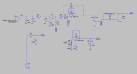
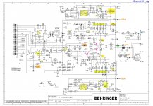
The schematics for input and switch boards are posted in #332.
Schematic and PCB design for a power supply are posted in #325.

More information about the muting module can be found in posts #237, #259 and #263. The schematic is posted in #262. Muting boards are now sold out. Gerber files for making your own boards are posted in #454.

Input board BOM: https://docs.google.com/spreadsheets/d/1ENt40kTZhL9ITpYthZ8c4qUfL6y8ajTpFsxg7ic-8vU/edit?usp=sharing
Switch board BOM: https://docs.google.com/spreadsheets/d/1gz4L44eWwEkDHWcEnBIwdIYa3pOwWgeSbLcd3dcf6AY/edit?usp=sharing
Muting board BOM: https://docs.google.com/spreadsheets/d/1mkKxl3J7ERI1Ij2h5PFqQ5qZ6s5hMIRs1WoFZ5Vm1gg/edit?usp=sharing

The default RPi connector PCB for V2 boards is designed for Raspberry Pi 2 and B+ models. If you are interested in connectivity for older Raspberry Pi A/B models or Arduino, and have not indicated it on the original signup sheet, please post on the thread.

Pricing:
Input board bare PCB: Sold out
Switch board bare PCB: Sold out
Assembled input board kit: Sold out
Assembled switch board kit: Sold out
Additional input board parts for balanced build: 5 EUR
Shipping anywhere in the world: 9 EUR

Assembled muting board kit: Sold out
Additional muting board parts for balanced build: Sold out

Input V2 features
  • Stacks on top of DAM1021.
  • Directly connects to J3 and J2 headers on the DAC without additional cabling.
  • Directly connects to Amanero USB adapter without additional cabling.
  • Directly connects to DIYINHK USB interface (the non-isolated version) without additional cabling.
  • Easy ribbon cable connection to WaveIO USB interface.
  • Directly connects to Raspberry Pi without additional cabling.
  • Additional connector PCBs can be designed to use other microcontrollers such as Arduino, BeagleBone Black, etc.
  • Can be controlled using the isolated serial port.
  • Serial port control from Raspberry Pi.
  • Coaxial SPDIF input with BNC connector footprint.
  • Optical TOSLINK input with footprints for Toshiba TORX147L and Cliff Electronics ORJ-5 receivers.
  • U.FL sockets for other I2S sources (can be installed, but not used simultaneously with Amanero/DIYINHK).
  • Optional U.FL sockets for Amanero MCLK OUT, I2S MCLK OUT, FPGA SLV and FPGA MCLK OUT lines.
  • External connections possible to ALL pins on DAM1021 J2 and J3, and to Raspberry Pi GPIO connector.
  • Two selectable I2S inputs.
  • Built-in regulated power supply for the isolated digital part/muting module/USB/RPi/other microcontrollers.
  • Amanero/DIYINHK USB status lines readable from Raspberry GPIO pins. WaveIO USB status lines can also be connected by manual wiring.
  • Supports true balanced configuration with two DAM1021 DACs. A single input board is needed for dual-DAM balanced build.
  • For true balanced configuration the second DAM1021 stacks directly on top.
  • Supports serial port chaining for true balanced configuration.
  • Supports separate access to each serial port for true balanced configuration.
  • EMI filters on I2S lines to reduce high frequency noise pollution.

Switch V2 features
The switch board allows DAM1021 input selection and volume adjustment by use of mechanical switch and potentiometer. It is not required if DAM1021 will be controlled exclusively by a microcontroller via serial port.
  • Includes a rotary switch for input selection
  • Input selections are "Auto", "TOSLINK", "COAX", "I2S-1" and "I2S-2".
  • Allows connecting a potentiometer for volume control.
  • Footprints for front panel indicator LEDs for DAM1021 POWERLED and input selection.
  • Includes ribbon cable for easy connection to the input board.
  • Supports true balanced configuration with two DAM1021 DACs. A single switch board is needed for dual-DAM balanced build.
  • It is an optional accessory for the input board and is not useable separately.

Muting board with alternative output buffer option.
Muting is done by shunting the unbuffered outputs to ground with normally closed relay contacts. When the relay turns on, mute is off. Since the DAM1021 pin18 muting control does not work properly as of the current firmware release, and it can be quite difficult to attach wiring directly to that pin, the mute control is implemented independently.
  • Stacks directly onto DAM1021 J7 header (the unbuffered outputs).
  • Fits even with the onboard XLR connectors mounted (although I do not recommend using them).
  • Power-on muting uses a delay circuit which turns on the outputs approximately 8 seconds after power is applied.
  • Power-off muting uses AC detection and will mute the outputs within approximately 30 ms after loss of AC power.
  • Optionally these timer based circuits can be bypassed and pin18 driven control can be implemented.
  • Includes PCB footprints for implementing SE to balanced output buffers using THAT1646/DRV134 chips using easy to solder through hole parts.
  • Supports true balanced configuration with two DAM1021 DACs. A single muting board is needed for dual-DAM balanced build.
  • Includes PCB footprints for implementing true balanced output buffers using THAT1606 chips (only available in TSSOP-16 packaging, quite fine pitched SMD parts).
  • For true balanced configuration the second DAM1021 stacks directly on top.

It should be possible to use the balanced unbuffered hardware setup for a 2-way crossover in single ended mode, although it has not been tested.

This wiki page contains documentation for the old V1.1 release of the input board.

Cassette deck question - what might cause mechanical hum during playback only?

Hi everyone,

I recently got a Yamaha KX-300 on a whim, thought I might get back into cassettes just for a change of pace.

The unit I got came with a very strange issue though. It emanates this low frequency "mmmmmmmm" humming noise during playback. This noise is mechanical in nature and is only present during playback, not rewind or fast forward. I have not tried recording yet.

Any idea where I might start troubleshooting?

Any suggestions would be greatly appreciated!

Cheers

H9KPXG Low Voltage On-Off Switch With Soft Start Boards by Mark Johnson

Earlier this year I ordered 25 H9KPXG boards through JLCPCB. I have decided to sell 20 of these boards. The H9KPXG, if you are not familiar, is a veritable swiss army knife for power startup and includes inrush current limiting, selectable startup delay, the ability to use inexpensive low voltage power switches on your front panel, and more.
The project is here if you are unfamiliar:

https://www.diyaudio.com/community/...ains-relay-includes-soft-start-h9kpxg.354971/

The boards were made to these specs:
* FR-4 base material
* 2 Oz copper traces
* ENIG finish

Plus, they are beautiful in black. 😉

Board prices are as follows include shipping through USPS, packaging and handling, and Paypal.

2 boards: $20
4 boards: $30
6 boards: $40

For orders of more than 6 boards, please contact me to confirm shipping and Paypal. The sales are for the boards only.

Apologies, but the sales of the boards will be limited to the US.

Feel free to post here or send me a PM. Thank you!


STATUS:

Just 16 boards left


DSC02304B.jpg

New Issue After logging in, messages and notifications do not immediately work

This is an FYI for the mods:

Since the upgrade I have observed the following behavior:
Each time I log in there are no messages or notifications shown.
As soon as I load a new page/thread or click refresh in my browser there are new messages or notifications shown.

It's not fatal, just annoying.

Sony TA-N80ES left channel died and I am not sure why, can I get some advice on the repair?

I just got a new (old) ta-n80 es amplifier and I had cleaned it, recalibrated it and thought I had it working, held the bias well, came out of protection etc. So I go to test it and get no sound. I tried a few things but nothing worked so I pulled the left channel input and put that into the fixed left input while the right channel was still in the variable input I also disconnected either just the left channel, or both I do not remember 100% from the pre amp while still keeping them connected to the power amp to see if tapping the connectors would produce anything. Before I could even try tapping the connector the amp almost immediately started smoking and shot into protection. After this I pulled it out with a heavy heart and started disassembling to see what went wrong. I found out that the driver transistors for the left channel, three of the six output transistors for the left channel, one of the 10 ohm emitter resistors, a zero ohm resistor and the left speaker relay had all gone. While very annoying especially after just spending a bit of money on this amp this is all fairly easy to replace even if the transistors might not be cheap. However I am making this post mainly to ask why this happened. Is the screwing around with the inputs the reason for this? I do not really understand why this would be an issue but admittedly I do not have a ton of experience with a/b power amps. I had it running on idle for atleast an hour to adjust the bias and it showed no signs of issues. I did redo the solder joints for the transistors but I checked for shorts or otherwise unwanted bridges and found nothing. And the 1 hour plus idle session was after this. While I had no sound during testing I also am not familiar with the setup and it is very possible I just connected something incorrectly. Since the dc offset adjustment was working I doubt that there was a relay that wasn't engaging or otherwise something obstructing the signal. I checked the manual on instructions that might caution the user to not use it in the way I did but I did not find anything like this either. Ofcourse that doesn't have to mean much but if there was such a confirmation I would feel much more at ease with repairing the amp by just replacing these components.

After some more searching and reading I figured out that the d312 diode is also gone. I have read that it is unobtanium but I am sure that some modern replacement will work.... The same diode on d311 is not shorted but it gives some unexpected readings (1.7 voltage drop one way, 0.3 the other) so I think I probably will have to replace both.

I will check all the other fusible resistors for shorts but for now I am planning to order:

Q404 2SA1306A-0 (toshiba) -> MJE15033G (onsemi)
Q403 2SC3998B-Y (toshiba) -> MJA15032G (onsemi)

both C3423 transistors read ok with a multi meter so I do not believe they need to be replaced.

C3856 (sanken) -> 2SC3856 (sanken) if chip one stop allows me to order there, otherwise 2SC5200N (toshiba) (non obsolete version of a transistor successfully used on a thread from years ago). I can also order these from digikey but they do not have the A1492.
A1492 (sanken) -> 2SA1492 (sanken) same story with chip one stop, otherwise I will probably opt for the 2SA1943N (toshiba)

As for the known bad resistor I will just order whatever is available locally that has the correct specs of 1/2 watts and being fusible. I am not sure yet if that is all that needs to be replaced. Input on this regarding the cause of the problem would be really helpful.

As for the relays I was thinking of just ordering the set sold on ebay for 12 euros, but it is not a priority. I think the old one might still work even if the plastc got very hot, even if it is just to test.

I would also really appreciate some input on the HZ3ALL diodes. In the aforementioned thread the suggested replacement was the Bzx55c2v7 which has some different specifications like a lower impedance rating and a higher max power dissipation. I do not know what should be prioritised in this instance in terms of specs but the Bzx55c2v7 has since also gone out of production so it is not an option.

Also mentioned in the thread was the UPA68HA UPA68 Dual N-Channel JFET being faulty. I checked it for shorts on my board and there weren't any but I do not know if that is enough to know if it actually ok or not.

As for the actual reason this happened, I am still not sure. When the left channel blew up I could hear sound through the left speaker so the speaker cables atleast on the left channel where connected. I am not sure if sound being produced in this situation means that there is no short or not.

Sorry for the likley disjointed post. I originally posted this to audiokarma and updated it as I went along. However during this process I noticed that a lot of the information that ended up being useful came from this website. As such I figured that it would make more sense to ask on here.
This is my first post here so I am sorry if I am not following some rules correctly. While I am sad that I killed my newly acquired amplifier I am also excited to potentially get it up and running again.

EnABL like treatment for surrounds?

I was looking at the purifi drivers with their weird-o surrounds and thought it might be possible to treat normal looking surrounds with thin sections of silicon caulking to damp surround oscillations. A stripe on the front then one on the back, maybe a dash dot pattern, maybe a pattern on the front inside edge or outside edge? I know people dope the edge of the cone, but this would be doping the surround in a pattern.

Would this do anything? Would it damp any resonances or just lower the Q by adding mass? Or, is enabl damping the cone more effective?

Anyone try something like it?

Help needed with Niles SI-1230 Amp

Hi! I'm looking for some help with a Niles SI-1230 amplifier I bought recently at Seattle Goodwill. It seemed like a great deal at $25. I'm looking to resell the amplifier but want to test it first to ensure that it functions properly.

Wondering if anyone can suggest what I can do to test it, and/or how to test it. I have a couple of small Klipsch Quintet speakers that have an impedance of 8 ohms that I could use. I also have a digital volt meter. I built a tube amp 15 years ago from scratch, so I'm not completely stupid with regard to electronics...I'd say my knowledge and experience levels are beginner+.

The amp powers on and shows a green light.

Any assistance or words of wisdom would be greatly appreciated. Thank you! -Joe

Switch for selecting speaker impedance output on output transformer

I have found a few threads that briefly address this issue, but they are not entirely clear. My output transformer has 3 different speaker taps for different impedance speakers. I notice that Decware sells amps with such a switch and further they recommend switching the impedance "on the fly" to see which sounds better with any set of speakers. Is it as simple as using a make before break switch? The threads I have seen appear to make the issue much more complicated, but they all seem to be using break before make switches. Can anyone give me assurance that a make before break switch on its own is sufficient? Or tell me what I need to do to make it safe to switch output taps "on the fly"?
Thanks for any suggestions.
Projects by fanatics, for fanatics
Get answers and advice for everyone wanting to learn the art of audio.
Join the Community
507,871
Members
7,891,648
Messages

Filter

Forum Statistics

Threads
406,409
Messages
7,891,648
Members
507,871
Latest member
captainmobley