EVA foam for performance speaker enclosures

I was very inspired by xrk971's thread Foam Core Board Speaker Enclosures? - diyAudio

When that thread started it was aiming at low cost, rapid building as the motivation for using foam. But it occurred to me that the right foam might actually be a better building material than wood for speaker enclosure. Wood is inherently a resonant material; it is used for musical instruments because of it resonant nature. Foam on the other hand is often used for soundproofing. Hit a piece of wood and it makes a medium to high pitched resonant sound. Hit a piece of foam and it sounds dead. As wood get denser, the sound it makes rises in pitch.

The Celestion SL600 and 6000 speakers from the 1980's also used a very different thinking for the enclosure. These speakers used a lightweight aluminum honeycomb material called aerolam.
Celestion System 6000 loudspeaker system | Stereophile.com[/FONT]
Celestion SL600si loudspeaker & DLP600 digital equalizer | Stereophile.com
And quoting from that article

The cabinet is unique to the SL600Si (and similar to the SL700) in being fabricated from a 0.5"-thick, metal-honeycomb aircraft flooring material. While low in mass, thus minimizing energy storage, it is sufficiently stiff enough for the resonances of its panels to be pushed almost two octaves higher in frequency than with a conventional wooden cabinet. The contribution to the overall sound from the flexing of the enclosure walls will thus be moved away from the region where instruments and voices have their energy maxima, and will also be lower in level. The result should be a low delayed-resonance signature, with correspondingly low levels of midrange coloration. Because the walls of the enclosure will now be virtually transparent to midrange sound, it is filled with carefully graded foam to absorb as much of the woofer's backwave as possible.
I always thought that celestion was onto something here with: low mass, low energy storage, and shifting the wall resonance away from the midrange.

Also when we build speaker enclosures out of wood, we have to line the walls to damp reflections, and fill the box to absorb the sound (make it non-transparent), and we have to add bracing and mass to the wood walls to damp resonance and vibrations. We have to apply all of these technique to compensate for the fact that wood is a resonant material with a pitch often in the middle-to-high-band frequencies.

As I looked around at different foams I realized that the ideal speaker enclosure material might be
- low mass
- semi-ridging / semi-flexible to have a low resonance frequency
- low energy storage
- sound absorbing (non-reflective)
- vibration absorbing
- and with a low resonant frequency (since a perfect sound absorber does not exist)

I found a foam called EVA which appears to have all these properties.
EVA Foam | popular Closed Cell Foam
intecfoams UK EVA
  • Impact and vibration absorption
  • Acoustic and thermal insulation properties
  • Buoyancy with low water absorption
  • Suitability for thermo-forming and thermo-moulding
EVA is also very easy to work with. It is one of the main materials used in costume building because of it's easy workability. Exacto knifes, glues, and heat guns allow for easy shaping into any form (curves, domes, facets...)
Creating a Costume/Cosplay from E.V.A Foam : EVA Foam & The Differnt Types Youll Use.
And EVA can be wet or dry sanded to create smooth surfaces, bevels, waveguides..
EVA foam also laminates very well to create thick panels. And I believe that the laminated EVA, with the multiple boundary layers, may have additional benefits.

I am posting this in the fullrange section because I think the fullrange crowd is open minded to experimentation, but I believe from my builds so far that EVA foam works just as well in multi-way designs.

I have two builds currently using EVA foam. A full-range sealed box with an FF105wk driver, and a 2way high-end build using a Satori MW16 and RS28f tweeter with a custom shaped waveguide and an LR2 crossover. I will be posting more details about these builds and my building techniques.

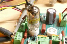
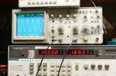
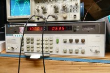
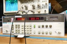
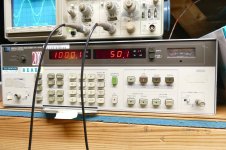
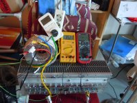
Some preliminary panel property testing. I will explore this more in the future once I can build a better testing apparatus.
Panel resonance tests:
http://www.diyaudio.com/forums/full...rmance-speaker-enclosures-16.html#post4456901

Panel transmission tests:
http://www.diyaudio.com/forums/full...rmance-speaker-enclosures-24.html#post4467017

Mattes flower speakers : OB fullrange using high density EVA foam for flower shaped baffles (shared by user Mattes, Oct 2018)
full range flower
with the 18" bass flower
My first flower petals experiment


I also started a thread on my multi-way experiments with EVA foam speakers over here OB compact 3way nearfield monitor

Hello from Oklahoma

Hello from Edmond, OK. I joined this forum because I have a Klipsch R-112SW that has developed the dreaded thumping sound. I am interested in finding someone that can repair whatever is wrong with amplifier/power supply. I have removed the panel from the subwoofer and conducted a visual inspection of the circuit boards. I do not see anything immediately obvious such as burned resistors or bulging capacitors. Any help would be great appreciated.

I spent 31 years in the Nuclear Navy in the submarine community. I started out in subs as an Electrician's Mate and later became an officer. I am now fully retired and no longer have the desire to tinker around with things like repairing circuit boards.

Thanks, Jim

The device that sums the signals, what does it called?

I'm searching for a device that could sum two signals together. Those signals are the outputs from the active crossover, high and low frequencies signals. I'd like to mix them together again after filtered. The purpose is because I still want the full-range signal but just want to adjust the levels of low and high frequencies independently. For example, the crossover point is set at 85Hz, above and below 85Hz will be independently adjusted levels.

1) What does the device that do this task called? a mixer, multiplexer, etc.?
2) Is it the same thing as the "stereo to mono audio converter"?

Ray Media RMC RL- s881. For McIntosh MCD201 CD player not working i want help about to find this

Hi, i have McIntosh mcd-201 cd player, my issue is i can't find his mechanism i have new laser lens. But can't find hole mechanism even not find in Google and nothing in replacement for Raymedia RMC RL-s881, please help about replacement or same mechanism finding...
IMG_20240213_233359336_HDR.jpg

Attachments

  • IMG_20240213_225254283_HDR.jpg
    IMG_20240213_225254283_HDR.jpg
    307 KB · Views: 221

MosFET gyrator in LTSpice

Hi,

I've put a generic gyrator diagram in LTSpice. This should simulate a choke with 47H and 60 Ohm.

The reason for this is that I want to "see" how much an AC signal on top of the DC is filtered by the gyrator. The input is 600 VDC with 0.5 Volt AC and a load (R4) of 500 mA.
I would like to use the probe in LTSpice to check all points of the diagram for voltages, currents, etc., but when I click RUN I get a list with parameters.
There is no parameter for the output AC voltage in this parameter list, so I still cannot check if it works.

I attach my .asc file and I hope someone with better LTSpice knowledge can make the proper adjustments to get this running.

Regards, Gerrit

Attachments

Starting my study on horns for compression drivers

good morning a friend of mine wants to set up a small disco in his basement
He knows even less than me about hifi but he would like a speaker with a horn on the mid-highs and he asked me to study the horns
I have a really strange question but I have to ask it
I have identified three main elements in a horn Horn, magnet and diaphragm
In my opinion in order of impact on the sound the horn comes first then the diaphragm and finally the magnet
Am I right?
Another question What would be the best xover frequency for a 2 ways speaker with a 10" woofer ?
i see commercial speakers crossed very high at 5kHz Is it not too high ? is it the best choice ?
thank you very much

Advice on bracing for travelers by Holtz and Campbell

Screenshot 2024-11-09 171726.png

What would be the best way to go on about this? In the illustration its 1 inch from the sides even though it says 2 in the document ( I think the illustrations are reused from the finalists which are a similar speaker)? I'm a bit lost on it since that would significantly reduce the cutout area. the dimensions of the brace are 24cm x 34cm. the effective dimensions are 24cm x 30cm since lengthwise 4cm is sitting directly under mid driver tunnel bracing. What do you think about going with an ellipse or circle cutouts with the same surface of the illustrated? Should I just do 2 inches on the sides and leave the middle without any additional bracing? Or just do the window thing?

Op-amp (or any feedback amplifier) stability and source impedance

Hi all,

On the thread https://www.diyaudio.com/community/...citor-for-a-fet-input-amp.419886/post-7843781 there was an off-topic discussion about source impedance and op-amp stability. It is obvious to me that for an amplifier with series feedback at the input and shunt feedback at the output, a too high source impedance with the wrong phase has the same kind of impact as too low load impedance with the wrong phase, because they are in the loop gain equation in a similar way, but apparently everyone else disagrees. In order not to contaminate the other thread too much, I start this one.

Attached is an explanation of my point of view, which was also posted in the other thread. As I wrote it in the middle of the night and wanted to get some sleep, I took a couple of shortcuts. I'll try to fix that over the next couple of days.

The replies to it were:


Best regards,
Marcel

Edit: the latest and hopefully greatest version of the report is here: https://www.diyaudio.com/community/attachments/sourceimpedance-pdf.1382244/

Attachments

  • Like
Reactions: Masca64

  • Locked
Single Ended, 40 VDC, 2 A, TO-220

More as an encouragement, and also to push the common imaginary boundaries in terms of parts and sound...

Roughly ahead:
A TO-220 generally sounds "better" than a TO-247. Cross-sections and shape are the main cause. The power and load specifications seem to discourage many audio enthusiasts from putting high loads on TO-220s. But don't worry: as always, first try;-)
It is also important to avoid connecting parts in parallel, as this leads to rounding and blurring of the sound. In addition, the practical layout of a paralleling is not considered by the vast majority, which in turn worsens the sound.

Here are two Single Ended to see: a BD711 (officially 75 watts and 12 A), a TO-220 power resistor and a trimmer each, at 35 VDC and > 2 amps. One input and one output capacitor. Nothing else. Sounds great;-) Although these BD711 are not audio suitable transistors.
Transformer here > 800 watts. I have a few 150 mF, 35 VDC electrolytic capacitors. A changeover switch with a load resistor is suitable as a switch-on delay. Quite pragmatic;-)
The heat sink is of course somewhat larger, capable of cooling around 300 watts passively and many thousands of watts actively.
It may well be that a water cooling system with radiators as heat sinks is cheaper than the one you see. I think I presented such a system - for such large projects - here almost 20 years ago. If you use anodized aluminium, a mica plate could be omitted. I also have powder-coated heat sinks that make a mica disk unnecessary. Anyone who has ever experienced the difference in heat dissipation...-)
And the sound, the distortion behavior of the heat sinks also modulates the current, i.e. the signal, i.e. the sound. I would advise consideration here.

With such an amplifier (textbooks at the front;-) you can let off steam with parts and their sound. It is worth testing a large number of them to get maximum performance. Because don't forget: every part modulates the signal with its character, which is not indicated in lines and numbers;-)
What always will remain: a clear, clean, contoured, powerful, max. dynamic sound, not feasable with analog pp.

One day I want to try where the load ends, replace the load resistor with a transistor, build the thing balanced, maybe one or the other...
... 2 x TO-126 instead one TO-220;-?
I'll report;-)

But first of all, this thread has been started to encourage.

Attachments

  • DSCN0613.JPG
    DSCN0613.JPG
    532.2 KB · Views: 318

Fake ELNA LAO 10000uf/80V from E-Bay seller

WARNINGS for "sharpseller2000" on E-Bay.
He sends out fake ELNA LAO 10000uF/80V capacitors.
On the picture in the advertisment he shows almost look-like-real ELNA LAO, but when you get it, it is a completely different capacitor!!
Marking on the fake is ELNA LA5 but color of the sleeve and print is not by ELNA standard.
After cutting of the insulation pad on the top, there is a deeply pressed cross on the aluminium can top. Not the ELNA sword like rupture engravings.
(You can also see the marker pen mark, where the new counterfeit sleeve negative should be)

Picture No 1 is what sharpseller shows in his advertisment
Picture No 2-4 is what you get when you buy it
Picture No 5, 6 and 8 is how ELNA LAO should look like.
Picture No 7 is a real ELNA LA5 capacitor in black sleeve with white printing

Price I paid for 10 pcs is USD80. I have had a long discussion with him, but he don't admit they are fakes. Just other Japanese ELNA LAO he says, because his supplier says so.
Even when the fakes he sent have LA5 printed in gold printing on them and have no ELNA can.

The last "offer" I got from him is a USD30 + postage USD32 in refund, if I return the fakes to him!! That means I would lose USD50 and have no capacitors at all!! And I dont belive at all, he will refund anythiong. Just try to stretch out the time so I will miss the opportunity to give him a negative.

"hi there,
refund will be just fine as i always do .
but my supplier is asking products return then i can get my money back. to be honest, i may not be as professional as you are, but i trust my supplier. will find out what is happening later.
before it .should i give you half refund $15 first? and after products return, then refund the another $15 half and the return postage as well.
hope we can solve the issue, don't worry about it.
regards
Harry"


I don"t trust him about anything, have now given him a negative feedback and dont expect any refund.

I also appriciate if other cheated DIY:ers here, share their experiances of other E-Bay sellers in this thread

JohanB

P.S.
Mesurements of the faked caps shows around 8200uF and they withstand 80VDC + 10% without leaking more than 10uA. ESR is around 50mOhm. What I can understand they are of some Nichicon series (because the cross stamp) or other no-brand Chinese manufacture.

Attachments

  • $_57.JPG
    $_57.JPG
    432.5 KB · Views: 2,580
  • FakeElna 002.jpg
    FakeElna 002.jpg
    765.8 KB · Views: 2,516
  • FakeElna 003.jpg
    FakeElna 003.jpg
    826.5 KB · Views: 2,460
  • FakeElna 004.jpg
    FakeElna 004.jpg
    748 KB · Views: 2,398
  • RealElna-3.jpg
    RealElna-3.jpg
    125.3 KB · Views: 2,419
  • RealElna-4.jpg
    RealElna-4.jpg
    11.6 KB · Views: 1,450
  • RealElnaLA5.jpg
    RealElnaLA5.jpg
    89.2 KB · Views: 1,463
  • RealElnaLao.jpg
    RealElnaLao.jpg
    137.1 KB · Views: 1,392

Meanwell gst160a whining and squealing through speakers

Hey everyone,

Please note I’m not an expert and this could be an obvious issue. Please take that into consideration as I’m learning.

So I’m putting together an amp using a wondom jab5 and a mean well gst160a

I know the amp is working because when I use a different power supply (mean well rsp 230 27) it works fine, there is a very faint white noise coming from the speakers but it’s very quiet.

But when I use the gst160a I get slightly louder white noise and if I connect an aux cable I get a horrible electronic squeal.

More info:

The power supply is connected using a kpjx panel mount to a power switch and then to amp.

My amp enclosure is plastic. It’s a 3d printed part.

I’ve also tested it outside of the enclosure with just all the parts loose and far away from each other.

I believe it’s related to the power supply as my other power supply doesn’t have this issue. (Note I don’t want to use the other power supply as it has a noisy fan which drives me mad).

Any ideas would be very helpful.

The jab 5 manual recommends the mean well gst160a so I’m suprised it wasn’t just plug and play.

Thanks so much

Will

DIY Case w/Thick Aluminum Front Panel, Switches, Pots, & Terminals

SOLD

DIY Preamp/Amp/DAC Aluminum Enclosure Case w/Switches, Pots, & Terminals

This is on the 'bay (with lots more pictures), which gives buyer protection and much lower shipping costs; currently no bites at $19 minimum bid.

Find by searching for "Preamp/Amp/DAC Aluminum Enclosure Case w/Switches, Pots, & Terminals"

Black anodized front panel is 17.25 in. wide X 2.4 in. tall X 0.26 in. thick

Internal dimensions are 17 in. wide X 5 7/8 in. deep X 2 in. tall

Height with feet is 2.7 in.

Top and bottom cases are 14 gauge aluminum (0.068 in.)

Already mounted on front panel are:

- 1 ea DPDT (ON-OFF-ON) power switch; see picture for ratings

- 2 ea DPDT (ON-OFF-ON) signal switch

- 2 ea DPDT (ON-ON) signal switch

Already mounted on rear panel are:

- 5 ea red-coded RCA jack

- 5 ea black-coded RCA jack

Also included but not mounted are:

- Illuminated pushbutton power switch (push on/push off)*

- Green pushbutton switch, NO (normally open)

The video shows the cosmetic condition of the front panel; note that at the bottom edge below the middle switch there's a little bit of missing anodize that I touched up with a black felt tip pen.

Also, the left and right edges of the front panel got scraped in storage, so I refinished them with a surface-conditioning wheel and painted them with a marking pen.

* I tested the illuminated switch for function; it lights up (upper and lower termnals), but I'm a bit puzzledby the switching terminals (the three in a horizontal row).

It can be either NO or NC by using the center terminal and one of the edge terminals, but the "on" resistance is 60-ish ohms; not sure what to make of that but I'm not really an electronics guy.

Attachments

  • 1731994644913.png
    1731994644913.png
    628.4 KB · Views: 199

JFETs - how to keep healthy soldering

I am not lucky soldering JFETs and MOSFETs, although I am careful with static electricity and such.

Now I can vaguely remember I read a long time ago FETs were sold with the three leads, gate, drain and source clamped together with a peace of metal to protect it. After soldering the metal was supposed to be removed.

Is that method still advisable?

Any other advise?

Thanks!

Phono preamp from the LT1115 datasheet

Hi all,

I would like to build the phono preamp from the LT1115 datasheet, the schematic shown on the first page of the document. This will be used with a Dynavector 20X-L (.3 mv - moving coil cartridge).

I have a few questions about the circuit:

The 2N4304 FET used to bias the LT1115 output in class A is no longer available, which component could I use to replace it? what about replacing it with a current source diode like the 1N5305 or even using a LM334 adjustable current source.

If I change the FET how can I calculate the value for the resistor in series with it? I can always go by trial and error... 🙂

Which component would be the best option in order to keep the noise level as low as possible.

What is the purpose of the 3n9 capacitor connecting the output to the ground? What about the 25K resistor marked as RL?

There is no coupling capacitor in the output of this circuit, should I add one, or is this not necessary with this topology.

What is the purpose of the 2200uF and 4.7uF (film) caps in parallel that connect part of the feedback loop to the ground?

Can I power this with +12 / -12 instead of 18 volts? what would be the drawbacks? If 12 volts is possible I could try to power it with batteries....

Thank you in advance,
Luis

A Hafler inspired solution for the phantom center image problem

For years I've been pursuing a way of getting better stereo sound like you get when you use a divider wall between stereo speakers to eliminate crosstalk and interference patterns. One way to do this is to add more channels using a matrix. A simple and well known matrix is to turn L and R signals into L-R, L+R, and R-L. What no one has ever told me is that this simple array will do amazing things if you space the speakers apart properly and listen at an appropriate distance. Center panned sounds only play through the center speaker, so there are no interference patterns so that solves the phantom center problem. But what happens when a sound is panned hard to the right or left? For a right panned signal you end up with the array playing a -R in the left channel, a R in the center and another R in the right channel. This of course creates interference patterns, but good ones! They work to create the proper stereo separation and never cause a null to cross our ears! This is because there is a null in the center of the sound field instead of a lobe. So each ear gets an appropriate stereo lobe! Each ear gets a lobe - so punny!

Here's a picture of my current array using basic little Sony SSCS-5 speakers

5SpeakerStereoArray.jpg

You can see I'm actually using 5 speakers here. The center channel plays full range down to 100Hz. The inside left and right play down to 600Hz. The outsides play 600Hz and down. This just helps to boost the stereo effect as the wavelengths start to get long compared to the width of the array. 3 speakers works great. 5 just gives it a little something extra and I happen to have lots of speakers and amp channels available.

Watch this video to see how the interference patterns produce excellent stereo throughout a huge range of frequencies. I used Falstadt's great ripple tank simulator to demonstrate how the effect works over a huge range of frequencies. http://www.falstad.com/ripple/Ripple.html. The three dots at the top of the screen represent an appropriately spaced array of 3 speakers playing a hard right panned signal. The circle down below represents the listener's head with strong signal reaching the right ear and weaker signal that is phase delayed reaching the left ear - as it should be. As I play a wide variety of frequencies you can see that strong stereo separation is maintained and no null from interference patterns ever crosses the right ear. You do get some weakening of the signal as the frequency goes down due to the center null widening so you can boost up the side channels in the lower frequencies or add a wider spaced set of speakers for the lower frequencies. I actually do both.

Login to view embedded media
So what happens with slightly panned signals? The same thing except the lobes are not as different, so no matter the panning there are no unwanted nulls from the interference patterns at the listener's ears.

Also notice what's happening off to the sides - not a lot of energy to light up early side wall reflections.

So how does it sound? I'm elated! It's great! It's not phase-y or weird. The sound stage is natural and oh so clear and smooth with beautiful separation and clarity. It's a revelation. On recordings with wild stereo effects they get really wild like they should. I don't see myself ever going back to a two speaker setup for high quality stereo playback. I tried having the outside speakers playing regular stereo from 600Hz down and it's just a downgrade. This is MUCH better IMHO even in lower frequencies where it looks like it's falling apart and just turning into mono. It's blowing my mind.

As a general starting guideline I recommend spacing the speakers at about 1 foot apart center to center for the 3 center speakers and put the listening position about 8 feet back. You'll hear some good stuff with just 3 speakers but you may need to put a low frequency boost on the side speakers to correct the tone for side panned sounds. You can do this by playing correlated pink noise and panning it left to right. Adjust the lower frequencies on the side speakers until the pink noise sounds similar in tone and volume across left, center, and right of the sound field. Experiment with spacing and listening distance. It's surprisingly flexible.

One difficulty is how to setup the matrix array. I use my Mac mini running Audio Hijack to do it in the digital domain. This allows matrix mixing and access to all 8 channels of my Denon receiver over HDMI. You can do a basic 3 speaker array using a 2 channel playback system by creating a L+R signal for the center speaker and a L-R signal for the side speakers. I run the L+R signal into the right channel, and the L-R into the left channel of the amp. The left channel runs both side speakers in series or parallel. Just wire up the right speaker opposite of the left speaker and it works!
I don't recommend mixing line level signals in the analog domain unless you have appropriate signal mixing hardware that that properly buffers everything. YMMV but my results were lackluster just using Y-connectors. I also don't recommend hooking multiple amp channels up to the same speaker unless you really know what you are doing. If you are using low pass and high pass crossovers on the outboard speakers like I am, watch out for phase reversals. Suddenly your soundstage is backwards!

12/30/2022 Update. After trying a lot of things I'm back to just 3 speakers. With proper spacing and the voids filled in between the speakers to minimize edge diffraction this really produces the purest sound and best imaging. I think I was tricked by the increased overall volume of adding more speakers. So there's something to that. If you have a lot of the same kind of speakers lying around and they can't play very loud, 7 of them playing at once makes a noticeably higher playback level possible than just 2 or 3 of them, and you can get some really great imaging. Turning up the volume a little to make up for the fewer speakers and I'm actually hearing better sound overall. This is great news because it's easier to set up as there are no time delays required and so a simple 2 channel amp and 2 channel dac can be used to power all 3 speakers. You just have to get the stereo signal matrixed into L+R and L-R signals. I heard one person say that the electric summing and differencing causes irretrievable loss of information. It does if you just take the L+R signal by itself, or the L-R signal by itself. But if you mix all the signals, including the inverted L-R, which gives R-L, everything that should reach the ears does. And, much less of what shouldn't.

Sourcing a PCM1702U

Hello 🙂

I'm looking to obtain one or two PCM1702U chips ideally U-K, after researching I understand they are obsolete. I have looked at obtaining an Denon DCD to strip out the original BB 1702. However I subsequently confirmed they don't actually have 1702, a couple of web sites had suggested that they do 🙁 Looking at other devices that might have 1702 its clear they are only on top end kit and as such its not cheap to pick up a retro device only to strip out the DAC's...

I'm based in the UK, has anyone had any luck obtaining copied chips? and if so please let me know.. or does anyone have a couple that are known to work?

Clarification regarding quality/fake chips (clearly the chip obsolete, and my assumption is the fake chips are just a copy albeit not quality checked nor will they have been laser etched i.e internal parts that make up the internal circuit and that produce the high level of quality output

Regarding the fitment of the chip.. I need a U (SOP), there are J which are inserted into the boards. Is it possible to source a SOP to DIP for a 20pin U to J (as I understand the wiring is slightly different?!)

Silly Question... but if a DAC is only converting Digital bits into Volts for an OP Amp to process... can i not just bypass the DAC and insert an alternative board.. that can process Data and Clock signals? (its a silly question)
Capture.JPG


sorry for all the questions 🙂

FS: Nichicon LKG Super Through Capacitors, 4700uF 63V

I have 8 of these Nichicon Type III Super Through with gold plated terminals, for the highest audio quality.
Initially I had these in one of my amplifiers but decided I need higher voltage, so I need to buy 100V capacitors.
Basically these are like new, barely used
I am asking $10 each plus shipping.

Attachments

  • Photo 2023-05-23, 2 54 39 PM.jpg
    Photo 2023-05-23, 2 54 39 PM.jpg
    312.3 KB · Views: 367
  • Photo 2023-05-23, 2 53 34 PM.jpg
    Photo 2023-05-23, 2 53 34 PM.jpg
    276 KB · Views: 333

Recommended "audiophile" speaker design at $500-1000 in parts (excl. cabinets)?

Recommended "audiophile" speaker design at $500-1000 in parts (excl. cabinets)?

Hello, fellow audio enthusiasts! My strive for ever-better music reproduction led me to a point when I'm interested in the level of sound quality that I can't realistically afford at retail. So I'm looking for a DIY design and I would be very glad to hear any recommendations in the target price range ($500-1000 in parts, without the cabinets). And by a "design" I don't mean a full kit; just build plans + easily obtainable parts as of now.

I have a small room, 20 meters sq. (215 ft. sq.). I don't have a preference as for bookshelf vs. floor-standers. I like the look of floorstanders and have the space, but if the speaker's F3 is above 35 Hz then I don't see the point in making it floor-standing since it requires a subwoofer anyway. I can't pull the speakers away from the front wall far enough, 80 cm between the front baffle and the wall max. (OK, maybe 90 cm if it's worth it!). I suppose this makes any open baffle designs unviable?

Basically, I'm looking for the best sound quality, clarity, imaging/soundstage and listener engagement possible in the price range. Which designs would you recommend for my shortlist?
P. S. A simple cabinet design (no odd shapes and curves) is a plus, but not a strict requirement.

Discrepancies in inductance measurements of identical transformers

Hello there,

about a year ago I purchased a pair of mains transformers for my Aleph J amp. According to the production data they must be from the same batch. Today I accidentally discovered that they are different, I mean the inductances are different.
The inductances were measured with a DER EE DE-5000 LCR meter at 100Hz. The values are as follows:
Transformer 1:
230V input - 6500mH​
18V out 1 - 121mH​
18V out 2 - 119mH​

Transformer 2:
230V input - 8900mH​
18V out 1 - 190mH​
18V out 2 - 188mH​

Although it is difficult to measure an iron core inductor, the error should be identical for both transformers. Is it not? Moreover, the measured inductances does not match the voltage ratio of the transformer (L1/L2=(V1/V2)^2).

How shall I interpret the results? Is there anything to worry about? Shall I try different measurement methods?

Both transformers are specified for 230V input and 2x18V output. I connected them and measured the output voltages:
Transformer 1:
230V input - 228.7V​
18V out 1 - 18.8V​
18V out 2 - 18.9V​

Transformer 2:
230V input - 229.3V​
18V out 1 - 18.8V​
18V out 2 - 18.9V​

As far as I can tell, if the inductance were different, the output voltages would be different. I am definitely missing something here.

P.S. I noticed that the "transformer 1" is clearly noisier. You can tell that it has more hum.

Attachments

  • IMG-20241117-WA0018.jpg
    IMG-20241117-WA0018.jpg
    161.6 KB · Views: 59

Replace Mospec BD907 in amp

Hi,

I received an amp and 2 days after, my amp blown. The problem was that my MOSPEC BD907 was broken. So I asked my local store a replacement part, and they gave me a MJE3055t. I replace the part and my amp is still on safe mode.

I asked someone to repare it and after verification, he said that I absolutly need the same MOSPEC BD907 or my amp will always stays on sade mode.

I can't find the same part at good price on the Internet.

Someone at digikey says that this part : onsemi 2N6487G will do the job to replace my Mospec Bd907.

Can someone help me with that? I don't want to spend too much for this amp and if someone can tell me what to with that it would be appreciated.

Thank you! (Sorry for my english i'm french)

Attachments

  • 17302385515227883914485615106365.jpg
    17302385515227883914485615106365.jpg
    645.2 KB · Views: 94
  • 17302385736831568331836000785213.jpg
    17302385736831568331836000785213.jpg
    630.9 KB · Views: 89
  • 17302385920825994050631614161925.jpg
    17302385920825994050631614161925.jpg
    325.1 KB · Views: 86

DC Voltage on Amp output and hiss

Hello, a friend gifted me a harman/kardon AVR255 7.1 amplifier. Front left speaker output is outputting DC Voltage between 1.73-1.93 V depending on the volume level. On the front right speaker could not detect dc volt output(0.03V).
Is that 1.73-1.93V DC normal? Why is it happening? Is there any chance that it could damage my speakers?

There is also a hiss on the front left speaker that you can hear if you go close to the loudspeaker. The hiss level remains the same regardless of the volume knob position

Semi-DIY Phono Preamp

Hello! For a couple of days now I have an urge to build myself a MM phono pre, based on (ripped off from) Pioneer's SA-9800 phono stage with some added bells and whistles like Signal Transfer's Devinyliser and Pass Labs' H2 for a sort of "tube mode" switch. Problem is, I'm sort of a dummy when it comes to electronics, I can solder, I've successfully serviced some turntables and cassette decks, but when it comes to schematics and PCB design i'm out (It will be my first time attempting something like this). I thought I'll just chuck a scan of the SM's PCB pattern into KiCAD and trace the whole board out, but do I need the whole board? Schematics show some rotary selector, but I don't need such things as I planned to make only one input and that's the MM only one (Phono 1). Could someone put me on the right path there and maybe help with determining what (if anything) could be removed from the board? Thanks in advance. P.S. Any pics of the board itself would be appreciated as well

Attachments

  • Screenshot_20241102-144405.png
    Screenshot_20241102-144405.png
    1.1 MB · Views: 133
  • Screenshot_20241102-144328.png
    Screenshot_20241102-144328.png
    1.5 MB · Views: 686

Desktop remote interface for Exogal Comet Plus DAC

Hi!

After trying a handful of DACs, I found love with the Exogal Comet Plus. However, it's user interface.... barely exists. It has a small silver LCD screen that can be a bit difficult to read and is primarily controlled via a BT remote or a depreciated app (Android 9 or lower only). Either remote option can be unreliable at times, so I set out to create a better solution.

My idea was to use an Arduino to directly send the remote commands, removing the need for wireless shenanigans, or to use a Raspberry Pi to operate the DAC from a web portal. I probed the DAC Bluetooth chip output but hit a dead end. Thanks to Bob (from Exogal) backing up some dealer info, there is enough documentation to use the TTL serial port on the back for firmware updates. Huge help and starting point. I reached out to Jeff (also from Exogal) who was immensely helpful as well, and helped me get the ball rolling.

Turns out you can control the DAC via the serial port! Using a USB-to-serial adapter cable, I wrote an app that interfaces with Comet! Written in Python since it’s what I’m familiar with. It’s a simple button-based GUI app that currently allows you to select which COM port to use, power on/off, select input and output, mute/half-mute/unmute, increase/decrease volume, or enter a specific volume value. All through the desktop app!

Mm6H2Pl.png


But I want hardware. Ran out of pro micros so I grabbed a few $5 Raspberry Pi Pico micro controller boards to try. MircoPython is great!
Login to view embedded media Login to view embedded media Login to view embedded media So far I've got most of the code sorted between a rotary encoder and a display. More work to be done but progress feels good. I plan to use 2x of those displays since I have a few already: 1x for big font Input/Output/Power, the other for Volume/Mute. Next up is to add an IR receiver to handle desktop volume adjustment and living room IR remote use.

Huge thanks to Jeff, Bob, and others for helping keep this DAC alive and well. Not sure how many people care about this, but I'd like to share it with those that do. Been waiting on solutions like this for a long while - long enough to try to do it myself. Thanks!

I want to applaud "Future Audiophile"'s coverage in two product catagories

NAD-C3050-Angle-Installed-1 copy.jpg


I have a friend who is looking to (retire), and to downsize and rationalize his audio system.

I say rationalize, because it's a lot easier to call up music from a streaming service like Qobuz, than to find a CD. On the other hand, he also has an LP collection that dates back to circa 1972, and he wants to be able to play an LP every now and then.

So, he asked my advice. Because I usually review components that are components, and not complete systems in one box, I went looking for benchmark reviews.

I found "Future Audiophile"'s coverage of Digital Streamers to be well organized, and very informative.

The other category I found to be very informative was their coverage of Amplifiers, mostly because "Future Audiophile" champions GaN (Gallium Nitride) amplifiers, and modular switching amplifiers based on Hypex or Purifi amp modules.

That said, the one unit that caught my eye, and I would appreciate any user comments on it, is NAD's Retro integrated amp, which has an optional card for BluOs and... Dirac Room Correction.

I'll have to look into whether it is set up for Qobuz, but right now it looks like a potential optimal choice.

Any helpful comments (or recommendations for competing products) will be very appreciated!

john

Phono pre to tape head pre-help with equalization

Hello. I have a phono pre built many years ago. It was an expensive project and worked very well. Problem is I do not use it since I switched to strain gauge system. It is the shame to keep it idle on the shelf.
I was thinking to redo it as a tape head pre for NAB decks. I saw many threads about doing it. Could someone take a look and direct me how to change an equalization from RIAA to NAB? I can follow a scematic but not much more.🙂
Thanks for help. Robert.

Attachments

  • IMG_20160406_163301-1.jpg
    IMG_20160406_163301-1.jpg
    53.2 KB · Views: 85
  • schema_7.jpg
    schema_7.jpg
    34.5 KB · Views: 92

For Sale Pearl 2 Preamp from Pass DIY, Complete

I'm letting go of my Pearl 2 phono preamp that has served me well for the past 6 years, built with matched Vishay Dale RN65 resistors. The boards were positioned so as to provide the shortest path to the RCA input connectors.

The preamp and its power supply are housed in Modushop Galaxy chassis with 10mm front panels and connected with a 6' power supply cable and Neutrik Powercon connectors.

The power supply utilizes an AnTek AS-0522 50VA transformer and EPCOS caps.

$300 + shipping, or pickup at an agreed location in the SF Bay area.

Current prices:
Boards and JFETS from Pass DIY, $200
Galaxy chassis, just over $100 + ~$30 shipping for the pair
AS-0522, $20 + shipping
Powercons, ~$16

IMG_4085.JPG


IMG_4094.JPG


IMG_4093.JPG


IMG_4091.JPG


IMG_4096.JPG

Of course it will work, it's guaranteed!

I have been working on a gain stage / driver circuit that is capable of delivering 100 volts peak-to-peak or more at a very low distortion level. The circuit is such that it will work with dozens of different tube types with minimal changes, just two resistor values. The test board has a 7 pin socket and a 9 pin socket wired in parallel so that I can try lots of different tubes. I have been going through my tube collection trying anything that will electrically fit either socket and taking data on what works and what does not. I had over 100,000 tubes thirty some years ago, but many have been sold, traded, given away or trashed over the years. There are still thousands of tubes in bags, and some boxed tubes in trays. I have a list of over 60 type numbers that will work in my test board, and I recently started testing some of the tubes in the board. I am now on my third 7 pin socket having run several hundred tubes through the first two.

Yesterday I came across a pair of boxed tubes with a rather strange label on the box. This is brand recognition at its best....NOT! I introduce the new "GUARANTEED ELECTRON TUBE." It appears to be guaranteed to be a "Used" or "Factory Second" tube. Not necessarily a good tube. Both are "TRU-Vac" brand, and even that is not "TRU." The 6CB6 on the left does work and produces some good THD numbers, sometimes. It is highly microphonic and will exhibit a G1 to G2 short whenever it wants to. A whack with a pencil triggers the short or clears it. The little 6AK5 lights up purple, gets real hot and outputs no signal, or random noise. Its vacuum is not very TRU as its getter is nearly gone. If I find any more of these boxes, the tubes will be "tested" before disposal!

Many tube rollers believe that tubes with yellow ink on them are better than others with the same type numbers. Previous testing with WE 417A's up against Raytheon 5842's show that this may have some merit as the WE's consistently beat the Raytheon's in THD testing, but they are slightly different tubes, despite some WE's wearing both type numbers. I have found 5 WE 6AK5's in a random handful of about 50 assorted used 6AK5's which were pulled from a much bigger bag. Note that the tube on the right has very little getter left. It has likely seen a lot of use. How well does it work? How about 0.148% THD at 35.7 Vrms (100 V p-p). The other four WE tubes all showed THD's under 0.2%. I have run a few hundred used 7 pin tubes through this board to test them. The scope screen shows two traces, the input and output signal after the level knob on the output trace was adjusted to overlay the two traces with a new tube. I tossed any tube that did not produce a THD level under 0.4% or when the two scope traces showed an abnormal gain or significant trace deviation when whacked with a pencil.

The circuit also works with the usual 9 pin TV IF amp tubes like the 6EJ7 / EF184. It is seen here with a 6KT6 in the hot seat making 0.169% THD. I have a lot more tubes to test.

During the development of this circuit, I saw a low of 0.0699% THD on one little 7 pin tube. When cranked to 50 Vrms (141 Vp-p) the THD went to 0.514%. The residual THD of my old HP204D oscillator is 0.04% at 1KHz. It is the better of two identical oscillators.

Before anybody asks, yes, I have stuffed two tubes into the board at the same time. Nothing bad happens, but the result is not worth photographing, just some so-so numbers with no smoke. So far, the only unexpected effects were some verbal outbursts from accidentally touching the tab on the mosfet while hot swapping tubes.

Attachments

  • P4070523.JPG
    P4070523.JPG
    417.2 KB · Views: 284
  • P4070528.JPG
    P4070528.JPG
    648.6 KB · Views: 240
  • P4070520.JPG
    P4070520.JPG
    297.8 KB · Views: 237
  • P4070484.JPG
    P4070484.JPG
    441.2 KB · Views: 237
  • P4070447.JPG
    P4070447.JPG
    402.8 KB · Views: 240
  • P4070442.JPG
    P4070442.JPG
    407.9 KB · Views: 230
  • P4070444.JPG
    P4070444.JPG
    398.5 KB · Views: 231
  • P4070445.JPG
    P4070445.JPG
    454.1 KB · Views: 237
  • P4070510.JPG
    P4070510.JPG
    408.8 KB · Views: 225
  • P4070427.JPG
    P4070427.JPG
    387.5 KB · Views: 234
  • P4070428.JPG
    P4070428.JPG
    407.9 KB · Views: 224
  • P4020471.JPG
    P4020471.JPG
    338.1 KB · Views: 209
  • P4020473.JPG
    P4020473.JPG
    355.9 KB · Views: 205
  • P4020472.JPG
    P4020472.JPG
    416.3 KB · Views: 222
  • P4020535.JPG
    P4020535.JPG
    403.8 KB · Views: 248

Output coupling capacitor size

Hi all,

for my phone project i am now designing the audio circuits.
I have a SIM module with a mono output and amplify it with a PAM8302A amplifier to a 8 Ohm speaker.

Now, there are tons of tutorials/post about chosing the right capacitor in terms of capacitance value.
My questions is: What about the power rating? I want my PCB to be as small as possible, and i'm afraid a too small SMD capacitor will pop on my PCB. After all, the whole power for this 1,5W speaker gets transferred through the capacitors. I haven't found a good answer yet.

Can you help with that?
(For reference, i will be using a 220 Ohm resistor in series with the 8 ohm speaker and a 47uF output coupling capacitor, to bring my cutoff frequency down to around 15Hz. I tried it and it sounds great).

Thanks and have a good day!
-Maik

Mystery Philips ECC81 tube code

Any Danes around? Bought a batch of tubes and this one had all prints scrubbed off. However, there was a code on the underside of the tube which revealed it was an ECC81 made by Philips in Copenhagen, Denmark. Horse-shoe getter and ribbed short plates. Strangely enough no date codes (may have been printed on the glass), only a "+" sign after the Copenhagen pyramid symbol. Can anyone shed a light on this?

IMG_6322.jpg


IMG_6318.jpg

What do you call the design that has mid woofer inside cabinet firing upward?

Hello,

I have vintage compact floorstanding speakers (JMR-Jean Marie Reynaud) which has a mid woofer installed inside speaker cabinet firing upward, and tweeter and another mid woofer facing forward. Is there specific terminology for this kind of speaker configuration? Not sure if it is called Isobaric configuration or another terminology for it.

If anyone educate me on this would be hugely appreciated.

Thank you very much.

Free: SOtM tX-USBexp card

I have a SOtM tX-USBexp card that I'm not using and want to give away. This card is a USB interface that you can add to a PC. I've used them with Windows and Linux.

Info: https://www.sotm-audio.com/sotmwp/english/portfolio-item/tx-usbexp/

Manual: https://www.sotm-audio.com/files/Accessories/tX-USBexp/tX-USBexp_Operating_Instructions_Rev1.7a.pdf

Local pick up in San Jose, CA or USPS flat rate $20 for continental USA.

Attachments

  • PXL_20241115_020712364.jpg
    PXL_20241115_020712364.jpg
    640.3 KB · Views: 79

Cheap but very good sounding opAmp recommendation for Fosi Audio ZA3

Hi, I'm looking for advice on a cheaper opamp for the fosi audio za3 that sounds as good as the burson audio v7 live, sparcos lab s 3602 opamps

It is impossible to buy Burson audio v7 live, sparkos labs ss3602 in Turkey and products coming from outside Turkey are subject to 60% tax and products worth more than 30 € are detained at customs, so I am looking for a cheaper opamp with good sound and I am waiting for your advice on this issue.

For Sale ICEpower 125ASX2 based amp complete

For Sale: ICEPower 125ASX2 amp module in a Carvin DCM200L 1U chassis.

Bandmates blew up original Carvin amp years ago, so I just replaced the Carvin "guts" with an Icepower 125ASX2 stereo module I had. I connected the aux power from module to the amp to drive the preamp / gain control and power / clipping LEDs in front panel.

Both XLR and 1/4" inputs work as inputs. Parallel switch in back will mono channel 1 input to both channels. There is an "EQ Expand" button in front that seems to change sound that also works...

How's $250 shipped conus?

Attachments

  • PXL_20240426_012636398.jpg
    PXL_20240426_012636398.jpg
    346.4 KB · Views: 287
  • PXL_20240426_012639846.jpg
    PXL_20240426_012639846.jpg
    481.2 KB · Views: 272
  • PXL_20240426_013758389.jpg
    PXL_20240426_013758389.jpg
    344 KB · Views: 236
  • PXL_20240426_013804878.jpg
    PXL_20240426_013804878.jpg
    357.8 KB · Views: 257

Understanding dipole "equivalent" layouts + possible pros/cons

I'm curious:
  • How many ways are there to generate dipole patterns?
  • Do any of the alternate approaches have particular advantages and disadvantages to learn from?

I've been reading a ton about open baffle designs, ranging from huge baffles to fully "nude" systems, and in all combinations of dipole + monopole combinations across the frequency spectrum.

Since most tweeters are monopole, many designers add tweeters on the back of the baffle/system. I've even seen this on closed box systems. It made me wonder in which ways that kind of solution might be better, different, or worse than dipole tweeters?

Could this extend to the midrange, say, with 2 mids mounted back to back in a tube the diameter of the drivers, wired out of phase?

What would happen as the wavelengths get longer... maybe identical sealed (or ported) chambers front and back, with the drivers again wired out of phase?

I'm curious whether any advantages (or disadvantages) could ensue:
  • Dipole sound, "closed box" aesthetic?
  • Instantly change your speaker from being dipole to monopole depending on the music or mood or room placement (e.g. shoved to wall or not) using DSP?
  • Other thoughts?

7.1 channel(4AES/EBU) to HDMI output converter

Login to view embedded media
Video equipment connection:
PC -> USB TO 4AES -> 4AES TO HDMI -> HDMI TO 4AES -> AES TO active monitor speakers

4AES is 4-channel AES/EBU digital audio signal, that is, 8-channel audio signal

1. USB TO 4AES: $120
2. HDMI TO 4AES: $190, DSP expansion card: $30
3. 4AES TO HDMI: $258.

USB TO 4AES
1. Supports WIN, Apple, and Android systems, plug and play. There are two models, one is an external USB interface box, and the other is a full-height computer baffle.

HDMI TO 4AES
1. Two HDMI inputs, one HDMI output, and the output supports up to 4K@30Hz.
2. 4 groups of AES/EBU outputs. The audio format required for HDMI transmission is LPCM, with a maximum of 8 channels
3. The DSP function can be expanded. The DSP expansion card is realized through the 4 groups of I2S interfaces on the motherboard. To use the DSP function, you need to use the sigma studio tool and have the USBi tool.
4. With remote control, multiple functions can be realized
If the DSP function is expanded, the remote control function can be customized
Dolby CP750/CP650 control expansion, etc.

4AES TO HDMI
1. 4 groups of AES/EBU input (can be changed to 8-channel analog input through appropriate modification), 1 HDMI output.
2. 4AES/EBU input can be input through DB25 or RJ45 interface.
3. Each group of AES/EBU input has ASRC sampling conversion function. The audio in HDMI is output at a fixed 48KH sampling rate.
4. Volume adjustment and other algorithms can be realized through the expanded DSP function.

Tube buffered LM3886

Hello everyone,

I decided to make a tube buffered IC amp, although tubers or gaincloners won't like it.

And I liked tubecad's tube buffered (with CCS) chipamp design. However, I have 12AU7, 5751 and a few 12AX7. To be honest, I didn't want to buy a 6DJ8 just for this project.

However, the CCS on the cathode of the tube is 10ma and this would be a high bias for the tubes I have. So I decided to use 2x parallel 12au7. This would give me a quiet bias of 5ma per cathode.

I decided to use LM317L, which I have used before and was happy with, set to 10ma, as the CCS.
And this is the circuit that came out..
What I want to ask is, this circuit gives THD values like 0.05% in the simulation.. Also, according to the FFT results, the weighted harmonic is 2. (A harmonic that I personally like) Do you think something like this is possible? Or is this circuit worth making?
Thanks in advance..
PS: 317's resistor should be 120 not 150...

Attachments

  • Hybrid Gainclone.png
    Hybrid Gainclone.png
    17.9 KB · Views: 347
  • tube.png
    tube.png
    14.2 KB · Views: 375
  • Like
Reactions: sercan85

Carver AV-405 power supply board protection circuit question

I would like to reuse my Carver power supply board for DIY amp boards. The board has 2 bridge rectifiers that supply different voltages. This would be useful for my project. There were thermal switches on the old amp boards. Can I use the board without them? Also, would this affect my speaker delay protection circuit on board ?

Attachments

  • Screenshot (75).png
    Screenshot (75).png
    1.1 MB · Views: 61

please criticize my design for a very large multi-way system

all right i'm attaching some sketches to help you visualize what i have in mind ...

this design has gone through a bunch of iterations and some aspects of it keep sort of vacillating which i will address later ...

for now i will just describe what the current iteration is, as depicted in the sketches ...

5-way system consisting of a center subwoofer stack that goes between the two main 4-way speakers ...

both speakers and subwoofer stack are 80" tall ( to fit in basements ) and the width is 32" for speakers because that's 1/3 of 96" that plywood comes in ... and 2 x 32" for the subwoofer stack. each subwoofer module is 25.5 x 32 x 40 inches, with a total of four modules. 25.5" is just 24" + 2 thicknesses of plywood. the main speakers would have approximately similar depth ( about 2 feet ) but since they curve towards the listener they don't have any hard number for their depth ...

in my sketches you can also see a 75" TV mounted on the subwoofer stack ... that is indeed where the TV will go but it doesn't have to be 75" ... although the width of 75" matches the width of the subwoofer stack exactly, which may or may not be a coincidence ...

total system width would be about 12 feet which is about as narrow as i could get it but it should allow it to fit in most living rooms outside of NYC and SF.

in the current iteration of the design the driver compliment is as follows

25 hz - 80 hz:
https://www.eighteensound.it/en/products/lf-driver/21-0/4/21ntlw5000-4350 liter net box, vented, tuned to 25 hz ...
four such boxes in the center behind the screen ...

80 hz - 200 hz:
https://www.parts-express.com/JBL-2262HPL-338312-004X-12-Neo-Woofer-294-45040 liter net box, vented, tuned to 70 hz
four 8 ohm drivers per side for a total 2 ohm load

200 hz - 800 hz:
https://www.eighteensound.it/en/products/lf-driver/8-0/8/8NTLW20005 liter net box, vented, tuned to 130 hz
four 8 ohm drivers per side for a total of 2 ohm load

800 hz - 3 khz:
https://www.bmsspeakers.com/index.php-62.html?id=bms_4594nd-midon the following horn:
https://www.bcspeakers.com/en/products/horn/1-4/0/ME4648 ohms ...

3 khz - 20 khz
https://www.bmsspeakers.com/index.php-48.html?id=4526nd2 x 2 array of 8 ohm drivers in series parallel for a 8 ohm load
the horn array will consist of four identical but not symmetrical horns that must be 3D printed
that is to say the arrangement of the four horns will be symmetrical but the horns themselves will be asymmetrical
the asymmetry will be used to bring the drivers as close to each other as possible, with magnets almost touching each other
all in all 8 identical horns will have to be 3D printed from a single file

main crossover will be MiniDSP 4X10 HD and it will plug in directly into the TV via optical Toslink ... i will throw some protection caps on the compression drivers to be safe as well ... the 80 hz crossover point will be realized internally to the 4-channel DSP amplifier that will power the woofers and subs

the TV will ultimately be the source, it will probably be a 2022 Mini-LED TV from either Samsung or Sony. i had a 2021 Samsung Mini-Led that i used as a source like this via optical output and it worked really well as the TV could do YouTube, Netflix and Spotify ... unfortunately it was a first generation Mini-LED and had a flicker so i sent it back to Costco ... in 2022 Samsung is coming out with 2nd generation Mini-LED and Sony is entering the Mini-LED market as well ... it will take time for prices on new models to drop but it will also take time for me to design and build this system ...

there will be a total of 3 amplifiers:

QSC PLX 2402 ( which i already own ) will power the 8" midbass array at 2 ohm, and will have a Noctua fan mod
QSC CX 404 ( four channel ) is $400 used on Ebay and will power all compression drivers, it will have the same Noctua fan mod
JBL Crown DSI 2.0 MA4 ( four channel ) will power both subwoofers and 12" woofers. this amp is expensive but it packs a lot of power and DSP and i may need those.

now for where the design keeps vacillating ...

i sometimes wonder if it's best to use 12" or 15" JBL woofers and whether it is best to use 8" or 6" Eighteen Sound tetracoil midbass ...

i sometimes wonder if the midbass should be vented or sealed ...

i sometimes wonder whether to use BMS 4592 mid, 4594 mid or 4599 mid ... the 1.4" throat versions can be used with B&C ME464 horn while the 2" versions would need either SEOS 30 horn or a DIY horn with 3D printed throat adapter and plywood mouth

i sometimes wonder if the system should be 5-way or 6-way ... in case of 6-way it would have an array of Six Beyma CP-12 Supertweeters crossed at 8 khz ...

i sometimes wonder if for tweeters i should go with BMS 4526 or Faital HF106 ... and in case of faital whether to use 1, 2, or 4 ... or if using Supertweeters perhaps a single Faital HF1440 ...

the reason i am using an array of tweeters like this is 2 fold:

- it lower distortion by quadrupling throat area thus lowering compression and distortion ...

- it doubles the coverage angle at the extreme high frequencies where horns begin to beam ...

yes i realize there is the issue of comb filtering and that's why i keep vacillating on what is the best solution in that area ...

as for what i'm trying to achieve with this is it is intended to be my main system for the foreseeable future - it isn't intended as any sort of exercise - it is intended to be THE system i use whenever i want to listen to music or watch music videos or movies at maximum volume ... it is intended to have the absolutely maximum performance level possible within what can be achieved in a system of reasonable size and cost ... spouse approval factor is not a consideration but i want to challenge myself by keeping it as compact and cost effective as possible - i could not respect myself if i went sloppy and simply started to mindlessly pile on heaps of subwoofers using "the more the merrier" approach ...

this system will be acoustically in a large space as the house is an open concept plan with one continuous space spanning from the porch to the patio and also both first and 2nd floors ... it's basically in a "living room" but it's also the same space as an eat in kitchen and sunroom and pretty much open to the entire rest of the house except bedrooms and bathrooms. the floor is wooden as there is basement below. the ceiling is sloped from 10 to 20 foot high. all other surfaces are fairly thin drywall and lots of windows - the house is mostly acoustically transparent - i don't expect much standing wave issues as i used to have in an apartment in a concrete building in NYC. on the other hand where i could fill that apartment with a single sealed 18" TC Sounds LMS subwoofer because those cinder block walls and concrete floors and ceilings trapped the bass and kept it resonating in the space ... by contrast in the space i'm currently in the bass will simply spread through the house and then leak out to the street so i need much higher bass output even for my listening position that will be about 8 feet away from TV screen ...

i have also been on a professional sound reinforcement forum discussing hearing damage and considerations for designing very high SPL systems like this until they eventually told me to go here instead because i'm not a sound reinforcement professional ... but before i was shown the door one good dude did give me a list of AES papers on hearing damage to read ( he wrote most of them ) so i'm currently reading that ...

the system in question is definitely deep into hearing damage territory but i'm trying to quantify it more accurately so i can optimize for lowest audible distortion at highest allowable levels and do so with the most compact and affordable system ... also read recently a very nifty article about audibility of distortion at different frequencies which allowed me to reduce the size of subwoofer array since as it turns out we are essentially deaf to distortion at subwoofer frequencies ...

don't be shy - i want to hear your criticism ! i will eventually hear it one way or the other and i would much rather hear it BEFORE i start building !

to conclude this post i will throw in some sample material i enjoy so that you can have an idea of what i will be trying to reproduce with this system:

Login to view embedded media Login to view embedded media Login to view embedded media
i occasionally listen to metal as well because i was a metalhead as a teen but for the most part these days i listen to electronic music with lots of deep bass.

Attachments

  • Main System Sketch.jpg
    Main System Sketch.jpg
    312.1 KB · Views: 335
  • Subwoofer Array Sketch.jpg
    Subwoofer Array Sketch.jpg
    311.6 KB · Views: 335

Hi-end two way

I would like to build a hi-end two way loudspeaker with a mid-woofer 6-8” in size, what driver would you suggest? I know this is the most boring speaker size in the world, but it is the most efficient size, in sound quality that is!

i want great bass and a fantastic midrange of course, and this is for a small room!

Crossover for BMS 4590 driver

Does anyone have any schematics for any proven "custom" crossovers for the BMS4590 ( 8 ohm ones) I have been unsucessfully attempting the flatten the response of these drivers by adding notch filters etc. ( running in a 200hz Le Cleach horn crossed actively @ 350hz)

I have looked on the web and have seen ones on german pages for eckhorns etc, and but i don't understand from my simple calcs what they are doing as the notch filters seem to be in places in the freq range where i don't think i need them.

Need help identifying potentiometers for an old Behringer mixer Eurodesk MX3282A

I'm fixing an old mixer and need help identifying replacements for two potentiometers
I'm able to find similar but don't know what kind of taper they have
They both seem to be made by ALPS and are externaly the same (dimensions bellow)

one has XC502 on the pot and 5kzy on the schematic and measures 5kohm - function: preamp gain

the other has ac503 on the pot and 50KG on the schematic, has detent at 12 o'clock - function: aux send

shaft lenght 18mm, including collar 23mm
shaft diameter 6mm
total lenght (excluding terminals) 30mm
body 9,85mm x 11,85mm

Is very similar to image bellow:
pot.png

Pass XP-20 with DB25 Mogami Gold

Hoping to hear from a XP 20 owner if they've tried one of the Mogami Gold db25 connectors as a replacement to the stock db25 with any success.

There was a similar thread on this HERE (since closed) but it was never confirmed if all pins are used for the XP 20.
Pin 13 appears to be open.

I've seen some db25 umbilical cables for Pass and McIntosh with good reviews, and high cost - I have access to Mogami db25 at no cost.

Appreciate any info others may have gathered in this same area.

Powered bass stand for ScanSpeak 7" 2-way

Hi everyone,

Sorry for getting theoretical here. I'm kicking around an idea in my head for next year, when my cards are paid off. I have a pair of 2-way speakers on stands. I am thinking of adding a bass section to fit below them.

The existing speakers use Revelator 18W/4531 and are about 12" wide. They're rather large due to the BR.

The plan is to seal them and run the upper section from around 200 to 300 Hz up. The bass section should be simple (sealed or BR) and will incorporate a 3-way Hypex plate amp. I'll be converting the passive speakers to fully active.

The bass section should be about 10" wide. I could see a pair of 8" woofers, or a pair of side mounted 10" drivers...

Bass should be solid, convincing but not looking to spend ultimate dollars. Also, plan on fully leveraging the EQ capability of the plate amp for room integration. Thoughts?

Intro

Hello everyone! Mi name is Enrique Spinelli. I have been working for many years on analog instrumentation circuits, mainly focusing on biopotential amplifiers. Currently, as a hobby, I am starting with low-noise balanced microphone preamps. I don’t have much experience in this area, but I hope to take it through this forum... I believe that some of my circuit designs could be adapted for audio applications. Best regards!

Three Way Speaker Question

Hi I am contemplating committing to a three way speaker design despite my preference for my current two way speakers compared with various compression drivers horn combinations in both two way and three way configuration. The current speaker is comprised of a Beyma 15G40 15" woofer and CP755ND 1.4" compression drivers mounted to wave guides actively crossed crossed at 700hz per channel. I was originally considering supplementing the bass section of the speaker with a second 15" woofer in the hopes of achieving a lower bass response however after some suggestions from forum members I am now considering an alternative design.

These are the three way designs I am considering. Any suggestions are appreciated.

-A Ciare 15.00SW 15" subwoofer driver crossed at 100hz, a single or pair of Beyma 10MI100 10" drivers in an MTM or TMM configuration operating from 100hz to 900hz, and a Beyma CP755ND from 900hz to 20khz
-A Ciare 15.00SW crossed at 100hz, a Beyma 15MI100 crossed from 100hz to 900hz, a CP755ND from 900hz to 20khz
-A Beyma 15G40 crossed at 250hz, a Beyma 15MI100 crossed from 250hz to 900hz, a CP755ND from 900hz to 20khz

The primary question questions are, is there an advantage to using a single 10" driver versus multiple 10" drivers in an MTM or TMM configuration? And is there an advantage to incorporating to a single 10" or multiple 10" drivers for midrange duties, compared with a single 15" driver? Any help is appreciated. Thanks.

How much does cooling fan air volume affect overall heatsink temps?

I wasn’t entirely sure of where to post this thread. I have a stack of Hafler pro amps, and I need to replace a couple of the fans in them. Amps use lateral MOSFETs that are hard to find and very expensive when you do. So I want to make sure that I have enough cooling for them. The fans are not overly loud, but it would be nice to make them a bit lower. I have a bunch of the Yamaha PC-9501n amplifiers, and they are dead quiet.

This is the current fan that is in them, as you can see the one in my hand is broken.

IMG_0066.jpeg

IMG_0070.jpeg


It is a 5 blade fan that draws 350 mA, I found that is spins at about 2550 rpm. I cannot find a spec for air volume on it. I did find another fan from the same company that has eight blades and has a speed of 2800 rpm. It draws 550 mA and moves a volume of 115 cfm. Clearly the fan in my amps will move less volume, but I don’t know how much less.

I purchased this van last night, it is referred to as one of the best performing fans if you want ultra quiet.
IMG_0067.jpeg

IMG_0072.jpeg


It’s spins at a speed of 2000 RPM and draws only 140mA. I found it moves a volume of 60 CFM. Do any of you think that this fan will be up to the task of keeping these MOSFETs cool?

You can see there is some space above the original fan. I was reading that there is another fan that may be even better, but it is 30 mm thick and not all scenarios can support that. I ordered a three pack of them, Phantek T-30.

https://www.phanteks.store/products/phanteks-t30-120-fans?variant=39439636856887

It spins at a higher speed of 3000 RPM, draws like 360 mA which is closer to the original and it moves over 100 CFM. I could run it at the lower speed of 2000 RPM and it will move 67 CFM, of course faster spin, speed and air movement equals more noise. So I was hoping to get your input on this, do you think that the Noctua up to the task? If it is, I will buy nine more and all of the Haflers with it. I’m just not sure how many degrees of difference on the heat sink there will be if you cut the air volume movement down. With the original fans, the amp do run warm. The amplifiers are biased to about 100 mA per output device.

Thank you.

Dan

Bose Acoustimass 10 IV Subwoofer No Sound. Help with burnt component identification?

I picked up this used Bose Acoustimass 10 IV speaker system. Speakers seem to work fine, but the subwoofer does not make any noise. So I took apart the unit and found some obviously failed (burnt) components:
  • 1x 3.14 A @ 250V main circuit fuse
  • 1x bridge rectifier GBU601. there's actually two of these on the board, one is obviously burnt and the other does not seem to have any anomalies like shorts. However I figure may as well replace both.
  • 2x diode. This is tricky because the only markings I see on it are: "617 402". No current rating or anything else. How do I figure what to replace this with?
There are also transistors SGSD200 (PNP) and SGSD100 (NPN). Couldn't seem to do the typical diode test on these, maybe due to how they are wired on the board. There's no obvious shorts, but I wouldn't mind replacing these just to be safe. One of these does seem slightly darkened. The part numbers show up as obsolete on Digikey. What do I look for in order to source a suitable replacement?

So plan is to just replace the components listed above, help identifying what diode and transistor to use appreciated. Everything else on the board otherwise looks fine. If there's other thoughts, let me know? Thanks!

See attached picture.

EDIT: I also just discovered that the small SMD resistor below the "O" in Bose may also be blow. See my post #15 below.

Attachments

  • PXL_20241117_025302435.jpg
    PXL_20241117_025302435.jpg
    899.9 KB · Views: 262

Beyma 12P80ND v2 and Faital Pro 10AK in 3 way open baffle?

Hi!
I'd like to build some 3 way open baffle using Beyma 12P80ND v2 as a mid and Faital Pro 10AK compression driver for the high frequency. For the low frequency I will decide later the driver(s).
Do you think it can be a good choice? Any particular horn in mind? I am looking at Faital Pro LTH 102, looks OK.
Any ideas for a good passive crossover is highly-appreciated.
Thank you!

how to connect BPA300 (balanced LM3886) to input and output?

so I have tested both R+ and R- by wiring them single-ended and they are working fine.

I want to try testing them now in balanced mode. And I have connected...
  • hot pin of the XLR (pin2) to R+ PCB (this XLR cable is connected to the XLR output of DAC. Volume can be controlled in the DAC so I set the volume to -90db)
  • cold pin (pin3) to R- PCB
  • positive terminal of speaker was connected to R- PCB output
  • negative terminal of speaker was connected to R+ PCB output
This connection results in massive hum. Do I need to connect the XLR ground to the PCB ground?

Thanks!
Projects by fanatics, for fanatics
Get answers and advice for everyone wanting to learn the art of audio.
Join the Community
507,771
Members
7,887,699
Messages

Filter

Forum Statistics

Threads
406,193
Messages
7,887,699
Members
507,771
Latest member
denengineer