Hello from Portland, Oregon

Hi all,
Just introducing myself. I've recently gotten into speaker building and home audio again after being interested in car audio my late teens and early 20s. My first full range project is going to be a center channel based around the Satori MT19CP-8 Coaxial driver, with full range front stage towers to follow. I'll start a build thread for these in the future once I start building the cabinets.

Cheers!

Options for Linear PSU for ACA

I'm building a stereo ACA, one chassis, two amp boards, one for each channel, with a linear power supply. I have a 300VA 2x20 toroidal transformer from Antek, and I'm planning to use a CRC filter. It seems to me that there are two options and I'm wondering if one is preferable to the other, what the pros and cons might be, or whether it makes any difference:

Option One: build a single power supply with one bridge rectifier and CRC filter, fed by the two secondaries in parallel, and feed both channels from this power supply.

Option Two: build two power supplies, each with a bridge rectifier + CRC filter, and feed one with one pair of secondary wires, feed the other with the other pair. One power supply would be for left channel, one for right. The two power supplies would be side by side on the same pcb.


It appears to me that option Two is used by the FirstWatt F1 amp, which has a single rail supply like the ACA. Other FirstWatt amps have one supply shared by both channels as in option One, but it isn't a good comparison because they have dual rail supplies, hence use two bridge rectifiers and two CRC filters, each fed by one pair of secondaries.


Also, some toroidal transformer manufacturers specify that the two pairs of secondaries are only to be used in series or parallel, and not independently, although Antek doesn't seem to give that warning. I read some posts about this issue, I guess it has to do with the amount of insulation separating the two secondary pairs, but I'm still unclear on just when that would be okay to do. Evidently it's not an issue for the F1.

Racer 8

This is the racetrack 8" driver that I introduced in the Bass Shelter thread. It is an unbranded driver sold as a replacement for a name brand boombox. It's 130mm slim across the narrow, and I can think of some fun applications if the driver is good. Build quality is visually superior to Dayton Reference passive radiators on hand. The driver is sold on Ali and is fairly expensive at $104 AUD for a no name. It's proportions and the promise of a decent 40hz low end as touted by the name brand makes it interesting enough to take a punt on. It will also suit the intended beach environment

1733826394190.png

Comes very well-packed
1733825458949.png1733825565576.png
1733825702369.png


On the Datsv3, driver not yet broken in
1733825850435.png
1733825978878.png


Will stick to plan and take power from the sub section of the current Logitech z623 for breaking in and initial listening. The driver doesn't come with radius info for the cutout, so I will have to do some trial and error to get it right. It does come with a template so I can hack out a cutout for breaking in purpose

Will use the laser cutter CNC router thingy to get the cutout and recess just right for a proper cab in due time. The driver also appears to require a dress trim. The screw holes are very close to the edge of the rubber roll surround glue line. I hate the idea of screw heads crushing this. What do you guys do in this situation? The best I can think of is an alloy plate dress ring in CNC and with matching screw holes to clamp down over the driver's folded up edge. Mounting from behind the baffle will solve this too and have the same clamping effect. Actually, this may not be a bad thing and the material thickness can contain the excursion and just allow a simple grill over the driver

Welcome your thoughts on this unit
  • Like
Reactions: Booger weldz

Hornresp model for Paraflex TOP

Hello,

I invested some free time to model the Paraflex TOP using hornresp Compound Horn Model CH2 released some months ago. It should give a good approximation once we can't have a perfect model considering this particular design but even using CH2 the results is very different from what people have been measuring.

Any thoughts to improve simulation?

Main differences between model output and measurements:
  • Left knee at 117Hz while measurements shown at 90Hz
  • Big SPL dip at 235Hz and 709Hz while measurements shown 1st dip at 1400Hz~1500Hz

Note: Due to shared holes between H2 and H4 segments, the H2 segment was simulated as constant CSA.

Attachment#1 - Proposed Hornresp Model
Attachment#2 - Hornresp inputdata and SPL based on latest drawing version G#1
Attachment#3 - Latest drawing
Attachment#4 - SPL measruments 1
Attachment#5 - SPL measruments 2
Attachment#6 - Hornresp inputdata txt

Attachments

  • Paraflex-top-System-Model1.png
    Paraflex-top-System-Model1.png
    16.6 KB · Views: 758
  • Paraflex-top-System-Model2.png
    Paraflex-top-System-Model2.png
    29.8 KB · Views: 547
  • PFX 1x12 top-150mm-FINAL.pdf
    PFX 1x12 top-150mm-FINAL.pdf
    4.6 MB · Views: 257
  • PARAFLEX 1x12 Kick-Top G1V2 Free Plan CC - measurement.png
    PARAFLEX 1x12 Kick-Top G1V2 Free Plan CC - measurement.png
    142.9 KB · Views: 496
  • PARAFLEX 1x12 Kick-Top G1V2 Free Plan CC - measurement2.png
    PARAFLEX 1x12 Kick-Top G1V2 Free Plan CC - measurement2.png
    147.3 KB · Views: 516
  • Paraflex-top.txt
    Paraflex-top.txt
    2.7 KB · Views: 123

Power Supply Soft Start Board (V2)

This thread is for discussions about the Power Supply Soft Start Board in the store. For more information on this product, please see the product page below.


Threads on diyAudio that relate to this product (If we have missed one, please post it in this thread and we will add it to the list):

A.S.P. - Version 2.0

Hi there,

Some times ago, I presented a tentative "Smart Fuse" for speakers:

http://www.diyaudio.com/forums/solid-state/255609-s-p-autonomous-speaker-protection-system.html

It was an exploratory, proof-of concept project, and although it did work, it had some issues, the main one being the current consumption, making it unpractical to use.

I have now solved these issues, and the version 2 is fully mature -and I am going to use it-

The excessive consumption of the version 1 was caused by the CMOS Schmitt trigger having its inputs biased in the linear region.
I therefore abandoned this solution, and at that stage, I had two options: use micropower circuits, comparators, opamps, regulators, etc. or opt for a completely discrete circuit.

I hesitated for a long time, but in the end I opted for the discrete path: there are plenty of micropower circuits around, but, they are mostly specialty circuits, specific to each manufacturer, generally not interchangeable or having alternate sources available, something I don't like very much.

The discrete circuit is significantly more complex, but it has excellent perfomances, can be built with commodity components and is extremely versatile and flexible.

The detection engine has remained the same, but all the rest has been modified.
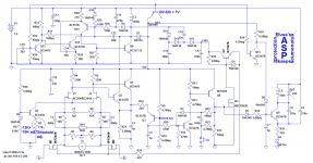
The main innovation is the use of a power converter to generate the supply voltages.
The quiescent consumption of the whole circuit is ~175µA, thus apparently not an improvement over v1, except of course that this current is drawn from a single cell, which makes a huge difference: the capacity is much larger, and the power density is also improved compared to a multi-cell battery.

The converter is built around Q9 to Q12, and does not require custom magnetics: an ordinary, two-terminal choke is sufficient.
It is messy and and complex, but it is worth the trouble: it works from 0.85V to several volts, is regulated, has an efficiency of 80~90%, even at low output currents, and its no-load consumption is only a few microamps.
It generates the 8V used by most of the circuit, and the 16V for the gates drive, via a voltage doubler (a tripler actually, because of the very asymmetric nature of the waveform).

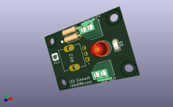
The trip indicator is now acoustic: a LED couldn't be driven directly from the cell, and connecting it to the converter would waste lots of power.
The buzzer driver is a single transistor oscillator, operating in "squegging" mode, to generate short tweets every two seconds.
It is very effective, providing more than 5Vpp to the piezo with a 1.5V supply, consuming only a few hundred of µA's.

Thus, even in the trip mode, the consumption remains well below 1mA.

The sound generated doesn't sound loud, because of the soft envelope of the bursts, but it is surprisingly audible: I can easily hear it over the 4 levels of my house.
It also serves as a low battery indicator, when the converter begins to loose the regulation.

The characteristics of the fuse can be tailored for any behavior: R19 sets the overall caliber, C1, C3, C4 and R6 to R8 dictate the frequency/DC sensitivity, while C2, C5, R21, R22 determine the temporal behavior.
The exact tripping threshold can be adjusted in several ways.

Although it will work on a AA battery (and last about 1.5 yr), I recommend a C or D size cell: the life will be practically the shelf-life.

Attachments

  • ASPv2.png
    ASPv2.png
    68.9 KB · Views: 702

Realistic inductance value in Output Transformer

Hey guys ! I have been building an output transformer to the Manual written by Robert G Wolpert.

A measure for primary inductance depending on cutoff frequency , -1db loss at the lower bound frequency f1 is given by:

L = (Primary Impedance)/(pi*f1)
here using my primary value of 4KOhm and frequency of 20Hz , I get an inductance value of ... 64 Henry. Which seems like a lot and not a very realistic value to design towards.

However , another equation that works using maximum flux density (B) is ;

N = (V * 10^8)/(K * A * f1 * B * 6.45) where A is the Bobbin Area and K is the stacking factor.

here using my values of V=346 , A=3.68 , f1=20 , B=14KGauss , a much more reasonable value of 1302 turns is shown.

So my question is , do I go ahead with the 1302 Primary turns to hopefully wind up a whopping 64 Henry primary inductance ? Or should I be less ambitious and go for -3db loss at 20Hz , or even -1db loss at 40Hz or so ?

Thank you for the help guys !

Adding JFET Source Follower to VAS

Conventionally, the VAS could be enhanced by adding emitter-follower at the front, shown as below. However, there is a drawback that the VAS transistor would overload and burn up in some situation.
1735745852328.png


I do know adding some protection components would solve the overload situation almost perfectly.

Anyway, I found another way to construct the VAS without worrying about overloading, shown as below.
1735746377106.png


Instead of buffering the input stage(IPS) with a emitter follower, you could buffer the IPS with a JFET source follower. Note that the JFET above is a P channel JFET. The voltage at the Gate is higher than the voltage at the base of Q6. It forms a source follower in a folded way. Thus, there is no fear that the Q6 would be overloaded.
Thanks to the high input impedance at the Gate. The amp has very high open loop gain at low frequency.

Loop gain:
1735746980973.png

MEH horns, Silver Flute 5.5 + OC25

I wanted to share a project and I hope this is the right place. Anyways here it is.

Below is this first and current iteration
20241020_113912.jpg

20241020_114010.jpg

20241020_115603.jpg

20241020_114056.jpg

These are 60x120 oblate spheroid horns that are about 17" wide. Most of the info I got was on this forum from patrickbateman. The taps are 3/4" 2 per driver and the chambers are 15mm deep plus frustums. The throat of the tweeter is about 2" deep which extended the tweeter response to around 750 if I remember correctly. The Soundstage is the largest I've heard which is exactly what I wanted for 2 channel movies and music. The main problem with these is that the way I attached the throat caused nasty vibes between the petg parts and I never got around to fixing it. I eq most of it out but certainly not ideal. Inevitably I knew I wanted bigger horns anyways which brings me to the next version

Screenshot_20241031_093317_Onshape.jpg
Screenshot_20241031_093332_Onshape.jpg
Screenshot_20241031_093437_Onshape.jpg
Screenshot_20241031_093608_Onshape.jpg
Screenshot_20241031_093620_Onshape.jpg
Screenshot_20241031_093642_Onshape.jpg

The main differences are the mid chambers are only 6mm deep and obviously the taps are oblong 3×.625. And the phase plug is based off of the new b&c drivers. Oh and its 27.5" (anyone wanna tell me how low this should load the mids?) Let me know what you think. Right now im wondering Are the frustrums a good idea for the taps or does this cause more group delay? Thanks in advance. 👍

Rotel RQ-970BX phono preamp issue

Hi all. I own a Rotel RQ-970BX phono preamp. Its recently developed an issue where after after about 10-20 minutes of playing it emits a big very loud kind of fart noise (sorry but thats the easisest way to describe it) that rapidly drops off in amplitude with loud bang at the end (which isn't great on the ears or the speakers) and then its dead - nothing. Turning it off for a few hours and then back on again it once again plays fine for 10-20 minutes and then same issue. If I just leave it on for an hour with out playing and then play something then its already dead.
Noteably when it is dead it is always dead on both left and right channels.
Im not an audio or electronic expert by any means, but it felt to me like it was probably a capacitor issue of some kind? Does that fit with these symptoms?
If it was one capacitor might that only kill on channel left or right - but not both?
I took the lid off and visually check all the caps for any sign of leaks or swelling but non show any obvious signs.
I though maybe just to try to replace all the caps in the output stages? but there are quite a few and its seems like a bit of work which might not address the issue.

Does anyone have any ideas or advice on this. Getting it repaired professionally is likely to cost more/same as buying another unit.
If this is a know issue that is likely fixable with a couple of cap replacements then Id be happy to try that but not really sure where to start.

Speaker protection and muting board, V2.0?

I have a diyAudio Speaker Protection & muting V2.0 PCB and most of the needed components.
I would like to sell it in the Swap Meet, but I don't think it will sell without a BOM and build guide. The link in the V2.0 thread to the BOM is broken. The link to the Build Guide is actually a link to the Soft Start Build Guide. Any chance someone can send me the BOM and Build Guide for the V2.0 Speaker Protection and Muting project?

High-voltage limits and insulation on (toroidal) transformers

I asked Toroidy to make a toroidal transformer with the following windings:
  • Primary: 2 x 115 VAC
  • Secondary-1: 350 VAC / 200 mA
  • Secondary-2: 350 VAC / 200 mA
  • Secondary-3: 420 VAC / 70 mA
They told me they can't make this due to concerns with high-voltage insulation. I don't know much about transformers, so I didn't think of this issue.

What are your thoughts? Is this really not possible? How much am I stretching the limits? Would another company be able to make a transformer according to my specs?

Greetings from Lithuania! DIYer, developer, supplier

Hello everybody.

I'm Vladimir

I have small repair/restore/manufacturing workshop with lathe, CNC mill, CO2 laser cutter, some linear & toroidal winding machines.

The main point of restoring - reel-to-reel magnetophones, cassette decks, vintage record players (turntables) and vintage audio of Golden Era (1920th - 1990th)

The main point of development - Hi-Fi & High-End audio circuits (semiconductors & tube), modules for upgrading or replacing failed in industrial audio units (including replacements for specific rarest chips or processors), unical applications for high-end devices etc. etc.

The main point of supplying - soviet-made vacuum tubes (appr. 100 models and over 9000 pcs in stock just now), new-made rare mechanical parts for vintage turntables and magnetophones (from simplest tonearm armrest hooks up to intemediate & pinch rubber rollers), and, of cource, transformers/chokes/coils and it's parts (bobbins, lamination, cores).

I can provide custom-made step-up (for MC or r2r magnetic heads), input and phaseinverter trafos as well as interstage or output. Also, in cooperation with my friend and collegue (the owner of former "Vilma" plant winding shop where are possibilities from the production of toroidal cores with 0.08 - 0.35 mm grain oriented steel tape + their oxigen free firing to vacuum impregnation and sealing of finished products with high-voltage varnish/resin, there are over 50 machines for EI & O transformers winding with a capacity from 0.1 watt to 20+ kw as well as there are motor's stator/rotor winding and balancing machines too)

Some of my developments and repairs you can see:
some of repairs - https://www.facebook.com/HighEndRestore
small part of developments - https://www.facebook.com/Audiophilia.eu/
a little of turntables upgrade decisions https://www.facebook.com/33strobo.eu as well as https://www.facebook.com/Strobeheaven/

Last development: LED VU-meter for cassette decks, r2rs, amplifiers as well as standalone decisions.
The main point - there are many different switchable visualization modes.
And most importantly - a freely programmable grid of step levels, 1-1024, unlike the vast majority of solutions existing on the market.
https://www.youtube.com/playlist?list=PLRAdaH_fmJTUvMvL2BAEi3Lc4zs5rIcr1

Greetings to all. Glad to be here.
  • Like
Reactions: tubelectron

Horn loading of cones and domes drivers (i.e. not compression)

Hi ! i understand that at least two speakers manufacturers (i.e. Avantgarde and Acapella) use horn loading on cone and dome drivers
I have listened to both in the past and i have been extremely well impressed by the clean and powerful sound
I wonder why they are alone in this approach
Then has anyone tried horn loading not compression drivers ? do horns for this application exist ?

MM Phono preamp issue

Hi,
A friend of mine drew the PCB of the mm turntable preamp in the attached diagram but it doesn't work. I have checked our schematic with the original schematic many times. I am waiting for your help.

Attachments

Which player to keep

Hi all happy new year,
Help please i have oppo 105d, oppo 203, zidoo z1000pro not done any ripping yet and need to get the hardware for the zidoo 4k external drive and memory which can be expensive, not sure if i should use an oppo to stream ripped discs and sell the zidoo. I was also thinking is i could take out the good part from the oppo 105 dac, power supply clocks and such and fit them into the oppo 203, would this work or will the swaps just confuse the 203 player. Or should i just sell the oppo’s and get good external memory base and 4k drive, though the hour an hours of ripping is putting me off using the zidoo. I was looking online and found who i think was russ andrews who did a service where you sent them your collection of cd’s and they would rip them for you and post everything back not sure if the same can be done for bluray and 4k disc’s, or do i sell the 105 and zidoo and upgrade the oppo 203 to later use as a streamer is i decide to rip my collection.
Hell of a way to start my new membership sorry but if you could help please.

Rectifier Snubber Daughterboard - roboDNA

Here is the gerber zip for my rectifier daughterboard. It's not tested yet but feel free to try it if you are brave. Using the gerber, you can get them made at PCB houses like JLCPCB for a couple of dollars for 5 PCBs.

After @birdbox and I test them, I'll post an updated version or version1.0 if nothing changes.

UPDATE Version0.3 - Made center hole larger. Removed rectifier pads from bottom of board. Moved resistor and caps further from rectifier.

NOTE: I used 2 toothpicks between the rectifier and board to ensure the case does not come close to the 2 rectifier tab holes which have a copper pad on the top later, and a copper hole. ( there are no copper pads on the bottom for any of the 4 holes ) I raised the rectifier off the board slightly since there is a small chance the manufacturing process may result in the copper holes extending above the PCB surface and making contact with the rectifier case. I doubt that would ever happen and I can't see the rectifier case ever reaching those areas, but still raised it off the board a bit. The other 2 holes ( + and - ) have no copper pads or holes so those would never be a shorting risk.

NOTE2: I included an image to show how the hole's copper may extend above the surface of the PCB. If the rectifier case is flush to the board, it possibly can slide too close to these copper holes ( within a couple of mm ) so use 2 toothpicks to raise the rectifier above the board. It depends on how the rectifier is manufactured, and some rectifiers could potentially have a greater offset than others.
roboDNA_Snubber.png

Attachments

For Sale NEW Toshiba 2SJ313 / 2SK2013 Quads (matched)

Hi,
I wont need all my transistors anymore, so i will sell a few quads that are left.
Each quad has 2 x 2SJ313 and 2 x 2SK2013.
I will ask 99€ for a quad.
I prefer shipping within europe, but worldwide is no problem (only fully insured), with tracking.
Inside europe shippingcosts are around 19€.
Paypal as friend.
Pictures can be added.

Regards
Alex

Christmas or Holiday Music

Christmas Music…you really only listen to it for a short period every year most likely.

It seems to pop up sporadically in the 15 Album thread.

I’m sure some love it and some…well, not so much.

I personally can turn into a bit of a Scrooge around the holidays.

However, I do have a few favorites I enjoy.

Putting on Vince Guaraldi’s A Charlie Brown Christmas usually gets me out of any funk I happen to fall into.

So let’s hear it…what lifts your spirits this time of year?

Merry Christmas!…Happy Holidays!…especially you Charlie Brown!

Hi DiyAudio from Uruguay!

Hi everybody!

My name is Juan, I'm from Uruguay. I always liked old audio equipment. Nothing too fancy though, I have other (more expensive) hobbies haha.
Lately I've been trying to fix and improve the gear I already have. I know Technics is a brand that doesn't get a lot of love. However as my dad already had some gear from them I ended up augmenting the collection.

I have several Amps (2x SU-C04, SU-C03, SE-C01/SU-C01, SU-V5, SU-V9), some tuners (ST-C01, ST-C03, ST-C04, ST-Z1), a couple decks (RS-M02, RS-M04), a turntable (SL-DL5) and some speakers (2x SB-F2, SB-F1MK2, SB-K915).

Several of these I fixed myself, as a way to learn more about how they work (and also the feeling of fixing something which was destined for the landfill is great).

I want to keep on learning more and more about electronics!

Float, roll and soar!

Hello all. Apart from audio types of things, I take a lot of joy in driving well setup RWD and AWD cars. My fav to date has been a Lexus SC400GT 4L v8 that had been set up by MINES for GT racing but then imported to AU and registered as a road car. Could show a clean pair of heels to most GT3 cars and turned heads

1733364105021.png


These days I lean more towards light weight and mechanical performance and attracted to the idea of kart type electric/hybrid cars and hope for regulatory changes allowing things like E-Cycle cars in the traffic. I am making an attempt at fitting something in between the clauses for road use

This is a reverse E-Trike project that I detailed in the Bass Shelter thread. I would have rather an E-Quad cycle, but the regs only support heavy weight for 4 wheels. The reverse trike format is to get around that and fit the cycle car under bicycles and tricycles section for legal road and beach use. I will develop this into a high quality vehicle with balance, handling and agility.

From a very early again, I have been very attracted to low altitude flying. I made and flew my first hang glider at age 12. Never quite did anything with it until about 4 years ago when I got into GEV or WIG and attained almost complete detachment from the water as the target for that craft. I am attracted to flying about just above the surface and skimming and such so an ambition is to develop a water craft based on my E-trike over time to attain complete detachment from the surface by the use of forward and rear wing foils

The Hyper car racing class in the World Endurance Championship is amazing, and the inspiration for some bodywork and aero will come from them. The dream is to have a nimble ultralight that can bank into turns in the air or on water, and also run along the very long sandbars and beaches here. My current Smartwave 3500 has been able to nail this on the water and almost in the air where it can take off to ride the peak of the tall chop with mods to the motor height and using COG well

Most of this will be done at 1/5th or so scale RC model as STEM projects for my daughter before we attempt full scale flying, although the chassis design is ready as the E-trike is a current active project. The RC scale chassis is actually built as and will also be an e-trike for the kids. The bass shelter thread has this one as a subproject due to wear some subwoofers

This kind of thing
Login to view embedded media Login to view embedded media

These are where my interest lies these days with motor craft and motorsports. It would have been awesome if there was a go-kart track in our area. There is one that was abandoned years ago

Would love to hear from you folks about your interests in motor craft and such. Anyone building a racer? RC? Did anyone follow the WEC? I didn't follow it but have been catching up on the rounds while recovering from burns and about to watch the final round at Bahrain. Following Toyota. Lost touch with F1 and others
  • Like
Reactions: stv

'Flat-pack' complimentary pair replacements for MJ15003 & MJ15004

Hello there, I hope you all had a great Xmas 🙂
I am out of touch with the newer 'Flat-pack' replacements for High Power TO-3 output transistors, like MJ15003 & MJ15004.
I understand that there is small selection of the newer devices that equal or exceed the 15003's and 15004's.
Could someone please post some examples with basic spec's. Or, post a useful 'LINK'.
Thank you.

Paralleling AD815 experiments

A while back the illustrious Jan Didden published an amp design using multiple paralleled AD815s. The packages he used were those suitable for bolting to heatsinks whereas I have several tubes of the SMT version which gets its cooling via its mounting tabs to the PCB. So I figured to try out mounting several on a bare copper double sided PCB. The top side is the +ve rail as that's the potential for the heatsinking tabs. Rail decoupling is supplied by the edge-mounted 'lytics :

Weixin Image_20241219102743.jpg

The above are a couple of early prototypes - on the lower one (stereo) I had the chips a bit too close together so they ran rather too hot. The second was just a single channel with greater chip spacing but at higher supplies still ran rather too warm. It took me a while but eventually I realized that much of the dissipation wasn't as a result of the load current, rather it arose due to the varying offset voltage of the AD815s. Put another way - there was too much cross-current between paralleled amps at DC. At first I thought that having a trimmer on each would fix that but then decided rather to couple the amps together with caps so the DC level became mostly immaterial.

Just this week I got PCBs back for a stacked version of this which gives nice flexibility of how many chips to use in different applications. For example, a mini desktop amp might only need 3 stacked boards per channel, giving 1.5A peak output current.

Stack.png


The general idea is to pile them up like this (subject to experiments to see how hot they get!) :

stacked.png
  • Like
Reactions: ra7

Hello, minidsp owner in need of some help with minidsp-rs on Linux.

Hello, I am a proud miniDSP 2x4 HD owner (in Romania). I have had this device already some 7 years. When I bought it I used Windows to configure it. Since then I changed from Windows to Linux. Recently I moved to another place and need to reconfigure my room and speakers.

I managed to use REW (on Linux) for measurements with my UMIK-1 mike, and found minidsp-rs, which is a Linux terminal program to control many miniDSP models (including mine).

The minidsp-rs instructions on Github are clearly not clear enough for me (see: https://github.com/mrene/minidsp-rs). I am stuck with importing files from REW.

Is there anyone out here who has already more experience with the minidsp-rs software?

Bridge Mode amplification and implications for Reduced Noise & Distortion

Hello there all,
It came to my attention years ago that 'common mode' noise could be reduced [in a cancellation way] by running amplifiers in Bridge Mode configuration.
More recently I read that depending on 'pre-stage' phase orientation, third harmonic distortion can actually be changed to predominantly second order.
Could someone please elaborate regarding this + the general Pros & Cons of Bridge Mode 🙂

Use Flex HT with 2x4 HT as active crossover for Biamp?

I have a 5.1 system with Electrostatic towers for the fronts and surrounds that I both have biamped and the speakers have the option to bypass the passive crossovers for use with active crossovers.

For this reason I would like 10 outputs so I can have high and low outputs for those four speakers plus an output for the center and sub. If I connect a 2x4 HD to two of the outputs on the Flex HT then will I still use able to use Dirac Live to configure those two speakers and their hi and low outputs?
I understand this will add an extra AD to DA conversion.

The other option is to run one pair of the speakers biamped with its passive crossover but I am hoping to figure out a solution so both pair of speakers can be biamped with active crossovers.

Any input is appreciated!

Does the use of passive attenuators ruin channel separation using single end connection ?

Hi.

If using single end connection to an amplifier with RCA connectors we have a common ground for both left and right channel.

Now, my question is like this : is there any problems using dual passive attenuators regarding channel separation in such single end configuration.

As we can see at the picture, attenuating 20dB for both channels using two Monacor attenuators will look like this :

IMG_0838.jpeg


Source impedance at the schematic input is 500 Ohm.
Impedance at amplifier is 27 kOhm.

We see the common ground between both channels .
Now, using passive attenuators:

R1 is 10Kohm and R2 is 1Kohm with each of the two attenuators.

Is there a channel separation bleeding between left and right channel using those attenuators and if there is, how big is the problem ?

TU-8200 Hum in Left Channel

(Reposting here as I suspect it will get seen by the right folks...)

I've got an original Elekit TU-8200 that I built back in 2016. It's developed a hum in the left channel, audible in the speaker as well as headphones. No change in volume based on volume control.

I've swapped all of the pre-amp and power tubes to no effect. Googling led me here and suggests I need to replace my FET(s).

I've measured the voltages at the documented test points, and several on the left channel are out of spec. Anything else I should check, or just order some FETs and swap them out?

Thanks!

Voltages (with 12AU7 and 6L6EH installed):

1 -> 3.8
2 -> 3.5
3 -> 3.6
4 -> 3.6
5 -> 123
6 -> 119
7 -> 127.1
8 -> 116.1
9 -> 220.2
10 -> 208.9
11 -> 1.1
12 -> 0.58
13 -> -20
14 -> -17.3
15 -> 0.03
16 -> 0
17 -> 0.46
18 -> 0.43
19 -> 285.8
20 -> 271.5
21 -> 285.4
22 -> 318.3
23 -> 291.3
24 -> 279.8
25 -> 287.4
26 -> -33.2
27 -> -34.5
28 -> 5.9
29 -> 6.2

Tangentially, and assuming I have to pull the board and solder on new FETs or other components, any must-have mods I should consider including? I built it stock 8 years ago, and was very happy with it new, but I also don't know what I may be missing.

Thanks all!

DIY winding machine

Hello everyone, I decided to build a machine to wind transformers and coils. I believe it can be useful for those who also want to build.

It is controlled by a computer via the USB port.

The shaft is driven by a stepper motor, as is the wire spreader.

One of the biggest difficulties was the wire spreader, where I wanted something with precision.
So I found something ready that can be bought for 20 or 30 dollars on those Chinese shopping sites, you can search for "mini linear guide with motor".

You will also need two stepper motor drivers, one to control the mini linear guide motor and the other for the shaft motor. A suitable one is the TB6600 - steper motor driver -

A USB interface to connect the PC and drivers. You can find it by searching on the same websites for "cnc usb mach3". It costs between 6 and 12 dollars.

A 24V dc or 36V dc, 2A power supply. 36Vdc is best as the motors can run faster.

As for the motor for the shaft, it can be reused from some printer scrap, or also purchased new from the same websites... the size of the motor depends a lot on the size of the transformer that you want to wind or the winding speed. I use a "nema 23" size motor.
They can cost around 10 dollars.

And some more pieces, some made by me, others I asked a friend to make for me... I think the photos will help anyone who wants to have one!
Lastly, the software is called Mach3, it has a free version, and I'm using a personalized screen that can be obtained from the software manufacturer's website

Confusion over Individual Driver Phase

Hello. This is my first real question on any forum of any kind, ever.
My question comes out of my recent completion of a pair of Discovery-4 speakers designed by Troels Gravesen. The speaker is a 4-way with 2 crossovers. The top crossover (@2500 Hz) serves a mid-woofer and the tweeter. The crossovers are second order and so the design calls for the mid-woofer to have its leads reversed on the mid-woofer to put it 180º out from the rest of the drivers. That's all relatively clear to me, though this is the first speaker I've ever built and have only the most rudimentary understanding of cross-overs. My question is this, "though the mid-woofer is hooked up electrically 'backwards' to the tweeter, is this simply correcting for (reversing) a signal from the cross-over that is itself out of phase with the tweeter?" I have run a test with an acoustic speaker phase tester and all the other drivers are in negative phase while acoustically the mid-woofer is positive. I would have thought that if the prescribed lead reversal was correcting for an out of phase signal from the cross-over, then the mid-woofer would be acoustically aligned in its timing with the rest of the drivers. So, if the mid-woofer is not only wired "backwards" but also is intended to be acoustically "backwards" that would say that I'm wrong about my assumptions regarding this all being a correction for an 180º signal with respect to the tweeter. In short, while the mid-woofer is wired in reverse, should all the drivers produce an acoustic wave that is in phase?

The second related question is this. If the mid-woofer IS intended to be out of phase with the rest of the drivers, then which way should I listen to these speakers, with the mid-woofer firing in the positive or with the other drivers firing in the positive? My Museatex Pa6i preamp has a phase control where I can easily choose.

Long-winded but I hope my question is clear enough.

Question about VituixCAD Merger Tool

Hey all,

Does anyone know exactly how the vituixcad merger tool works?

I have a side firing port on this speaker I made. The merger tool seems to add in the port and its resonance as if they were both pointing forward. I would think that the resonances would all be far less if the port was side firing or rear firing.

Is there anyway to model it side or rear firing in the VituixCAD Merger tool? Or is there a way to take the port measurement as if it was side or rear firing? The only way I know to take it is inside of the port near field which, clearly, is at 0 degree to the port.


My port resonances are pretty bad and I am wondering how much of these resonances I am going to have to include into my crossover network. The last two bass reflex designs I made were front firing ports so this was not an issue. Their resonances were minimal.

Let me know if you have the answer to any of these questions. Thanks for reading and thanks always for any replies.

Attachments

  • Side Fire.png
    Side Fire.png
    655.7 KB · Views: 42
  • Merger Tool.png
    Merger Tool.png
    786.9 KB · Views: 38
  • Screenshot 2024-12-31 151458.png
    Screenshot 2024-12-31 151458.png
    619 KB · Views: 39
  • PXL_20241228_205126020.jpg
    PXL_20241228_205126020.jpg
    400 KB · Views: 37
  • PXL_20241230_030441064.jpg
    PXL_20241230_030441064.jpg
    712.9 KB · Views: 37

Moscode 300 problem

I have a Moscode 300 which lost its left channel. Could a static electric shock do this? I walked across a wool rug in rubber soled shoes to turn the amp off. Heard a rather loud pop when I hit the power switch. Turned it on again, the left channel is dead. Fuses are OK. I have a schematic, but not the skills to locate anything other than obviously bad components. Any ideas? Thanks very much.

power supply grounding in a stereo amplifier (2x mono amp) in 1 chassis

some info:
  • each channel has its own power supply and transformer
  • ground for the power supply is derived from the center-tapped transformer (see screenshot below)
  • only 1 AC input for the 2 power supplies
question: should I connect the 2 power supply ground together? I'm only asking since I want to install a ground loop breaker.

Thanks!

1735642988829.jpeg

[Infinitas] USB Audio Class 2, freeDSP, 32 in, 32 out

Hello diyaudio,

I would like to present you my latest diy project called [Infinitas].
[Infinitas] is a modular USB Audio Class 2 interface.
First there is the interface board itself. The features are:
USB connection for UAC2 operation exposing 32 inputs and 32 outputs to the computer. It uses a XE216 MCU by XMOS. All audio streams are routed to a MachXO2 for signal distributing/routing. The MachXO2 either routes an audio stream to the optional DSP or to the expansion headers.
There is an optional DSP on this board. It is an ADAU1452. This can be easily programmed by SigmaStudio. With this DSP [Infinitas] becomes freeDSP-Infinitas.
As I said the DSP is only an option.
The board has wordclock in and out. It uses a CS2100 for the PLL.
It works at 48kHz, 24bit. Making 96kHz samplerate available will be the next software mod.
To this interface board you can connect up to 32 inputs and 32 outputs.
I have already designed one expansion board with 8 balanced audio inputs and 8 balanced audio outputs utilizing AKM4458 and AKM5558. For my prototype I connected four of these boards to get 32 input and 32 output channels.
Currently, I am busy with designing digital I/O (ADAT, AES3, SPDIF...) expansion boards.
Since this project has a strong connection to the freeDSP project the expansion headers use the freeDSP I2S expansion header pinout.

Because the USB implementation is UAC2 compliant it works driverless for macOS and Linux. It does also work with the usbaudio2 driver of Windows 10 together with asio4all. No additional driver needed. For older Windows versions you have to use one of these open source usbaudio2 drivers from the internet or buy it. Please refer to the XMOS website in order to get some links to driver manufacturers if you are not using Windows 10.

I'ld like it to see other audio enthusiastic makers designing their own expansion boards. Therefore, I made the project open source hardware and published everything on github. Please refer to freeDSP | An Open-Source Low-Budget Audio DSP and watch out for "Infinitas" and "AnalogIO x8". There you will find everything you need.

I hope you enjoy this project as much as I did. 🙂

Raphael

Attachments

  • IMG_0534.JPG
    IMG_0534.JPG
    371.7 KB · Views: 810
  • IMG_0536.JPG
    IMG_0536.JPG
    360.1 KB · Views: 805

Amp Power LED Carrier Board

I spun up a small LED board for my amp and am posting it in case anyone wants to use it. It can be mounted to the 10mmX10mm grid and also the front panel with POT and LED through the panel. The POT should fit through a hole beside the LED if PCB standoffs are used and the headers are mounted on the back of the PCB. I have a footprint for both throughhole and surface mount LEDs ( using light tube for smt ). I used 2 resistors before the POT so a photoresistor can be used too. ( not using it on mine yet but left the footprint in case ) Resistors are 460 and POT is 5k. You can only use 1 resistor if you want, by crossing the 2 resistor footprints with 1 resistor where the white dots show.

I also added an LED output header in case the LED needs to run to the front panel. ( no need to populate the LEDs on the board )

The center of the POT is 15mm from the center of the THT LED, and 20mm from the center of the SMT LED.

I used POTS from tayda: A-597 or mouser: 652-3296W-1-502LF

Attachments

  • roboDNA_AmpLED_Element.png
    roboDNA_AmpLED_Element.png
    102.3 KB · Views: 79
  • roboDNA_AmpLED_Element_v0.1.zip
    roboDNA_AmpLED_Element_v0.1.zip
    64.3 KB · Views: 40
  • roboDNA_AmpLED_Element2.png
    roboDNA_AmpLED_Element2.png
    80.3 KB · Views: 73
  • roboDNA_AmpLED_Element3.png
    roboDNA_AmpLED_Element3.png
    81.7 KB · Views: 61

6V6 - 300B Circuit idea

I came up with this idea after researching tubes I could use to drive the 300B, 2 stage, non-inverting, tubes that are manufactured today. I remember building the Salas preamp years ago and it sounded pretty sweet. I've heard the driver stage makes or breaks the 300B magic. What are your thoughts, should I give it a try?

Attachments

How is 25v AC voltage dropped to 10v DC with only a diode based rectifier

I hope I'm posting this in the right place.

I need some help getting my head around this power supply schematic for a Philips CDM2/10 and boards in my B&O CD3300 cd player. The picture is an extract from the decoder board circuit. The +/-10v feeds go to the servo board. The problem is the supply going to the servo board is actually +12 & -13v. At first, I thought it might be a faulty voltage regulator, but the supply doesn’t use any.

The 25v AC comes in from the connections P41 – 4,5,6 and 7 on the right of the schematic.

My question is, how does it reduce 25v AC down to 10v DC with just rectifiers and capacitors? I assume the capacitors in the circuit are there to smooth out the supply. I think each diode should drop the voltage about 0.7v but can’t see how these give a 15v drop in total.

I’ve tested the input AC and it’s actually 20v, measured across the 2 feeds. Did I measure that correctly?

In case it helps, I’ve changed C2397, which was reading OK, when I re-capped all the board a few weeks ago. I did not change C2396 as I couldn’t find an exact replacement. The original is enclosed in a can with one +ve and three -ve connections. I have a new one with the correct voltage and capacitance with one -ve connection. I assume this will work if I connect this to all the relevant grounds.

I’ve tested each of the diodes, in circuit, and each one gives about uf=704mv, c=93nf and Ir = 7uA. I have some new ones on order, but before I change them I wanted to see if I was wasting my time as the problem is elsewhere.
CD3300 power supply schematic.jpg

SSL Handshake error on 31 Dec 2024, California USA

Hi, when I clicked on the notification bell at top right and began to click on my unread messages, I got the error page shown below. I apologize that I don't know whether this is serious, slightly interesting, or normal everyday baloney that can be safely ignored. I searched for threads with SSL Handshake in the title, and found none. -- MJ

_

Attachments

  • 2024_Dec_31_0543_Pacific.png
    2024_Dec_31_0543_Pacific.png
    90.6 KB · Views: 62

What to do with a BlieSma T25B-6

Hi guys,

My first thread here, need bit of advice. I have a pair of the T25s and I am looking for a well documented project that can make best use of one of the great tweeters around. I have access to top level 3D printers and people who know their stuff around those, 5 axis CNC is also something I can use. So a very elaborate enclosure or waveguide is something that I would be happy to do to complement it, really hoping to make it right. Amp is the new Purifi 1ET9040, DAC is Soekris DAM1941 with some mods. Thanks in advance!

Midrange or mid-bass driver back protection chamber

Dear all,

Perhaps I have stupid question, but I have to...

I need a solution for enclosure or chamber which is mounted inside of loudspeaker cabinet to protect midrange or mid-bass driver from bass driver interferention. It must be sealed solution, no matter is it just aluminium cover or construction of MDF or plywood. As you can see - I know how to do it, but is there any simple way to do it? Where I can (perhaps) buy this cover? Is there any special name for this, because I cannot find something good... If I'm going to build - it will take some time and efforts.

Any suggestion?

Best regards to all and a Happy New Year...

Cheers!

Boris

The Lumino's - Waveguided DX25TG59-04 paired with a RS150

Hello everyone,
this project / speaker has been in the making a long time. It is my first ever completely self-built speaker and I learned a lot on the way.
My DIY-speaker journey started with the gloryful C-Note's but I always disliked their looks. When I saw a Buchardt speaker I was basically already sold as I think they are beautiful and wanted a pair but couldn't justify their pricing. So I thought, what is stopping me from building a similar speaker?

This speaker is by no means exceptionally good, the crossover needs some tweaking, theres a nasty port resonance I cant get rid of and some other small stuff but I like how they turned out and maybe someone here is looking for this type of speaker. Unfortunately I haven't got many pictures of the building process but rather of when the speaker was finished.


Parts used

Dayton Audio RS150-8
Peerless DX25TG59-04
Visaton WG-148R
Monacor BR-70HP port cut to 18cm length

You'll need a 3D-printed adapter to connect the tweeter to the waveguide. One also needs to remove the original faceplate of the tweeter.
The files for the adapter are available here: https://www.thingiverse.com/thing:4714668
You'll need the XT25 file for the fitting adapter.
Don't forget to mark the tweeters +/- poles as you won't know without the original faceplate installed.

Cabinet

18mm MDF was used.

17x32.5x27 (WxHxD) [cm]

tuned to 53hz

Pictures

Lumino_front.jpeg
Lumino_back.jpeg
Lumino_inside.jpeg
tweeter_adapter.jpeg


Crossover & Measurements

The crossover is very simple and cost-effective. Crossover-point is 2.3kHz but the tweeter can probably eaasily handle a lower one.
When measuring the built speaker the tweeter seemed to be even more sensitive than when I originally measured the drivers. If one wants to build this speaker he should experiment with different resistor values to find his own sweetspot. I started with a 3.3Ω but the tweeter was definitely too bright with it. I settled on a 6Ω but as the measurement will show the tweeter is still a bit loud with it, but I like how it sounds.
As I said, the crossover could still use some work to be really good.

Actual response is merged with nearfield port measurement. Merged at 100hz with 4 octave blend. Notice the port-resonance at 720hz (any tips?).
Unfortunately I haven't made any directivity measurements yet, but I think the speakers would measure just fine.

Crossover.png
Simulated Crossover Response.png
actual response.png
impedance.png


Final thoughts

If I had to build this speaker again, I'd definitely do some things differently, but I guess thats just part of the learning process.
  • The cabinet could be built a bit shallower to get even closer to that buchardt look.
  • Different cabinet bracing, im not sure if the current might actually introduce the resonance.
  • I'd recommend a different port, the cutout for it was really hard to get right as the port sits on a very small recessed area and no screws are used.
  • Obviously the woodworking in general, the finish looks awful lmao
  • Get a proper measurement mic beforehand, this actually stopped me from continuing this project for a long time.

Thanks everyone who helped along the way and might still be able to add to this project, I appreciate feedback anytime.
  • Like
Reactions: morbo and motokok

Driving an open baffle opposing-driver sub-woofer

Background

See attached 2 (rather dusty) photos of an old open baffle opposing-driver sub-woofer project, I want to resurrect.

It uses:
  • a pair of 15" PrueAudioProject woofers, which PureAudioProject had Eminence optimize for open baffle.
  • spacers to connect the drivers
  • wrought iron table legs from which to hang the drivers
  • rubber tie downs as the suspension
In the past I drove this speaker with a stereo amp, one channel (same signal) to each driver.

Of note, in this kind of speaker, one needs to connect the drivers out-of-phase.

It worked great and matched very well with my large aluminum honeycomb DML main stereo speakers.

Next step

I have all the parts to construct a second one of these.
I don't have an extra stereo amplifier.

Key specifications of the drivers:

1728834634624.png


Questions

I have a stereo amp: Hypex NCore 2x125W 4 Ohm
I used this amp to drive this sub in the past (one channel to each driver)

Can I use this amp to drive two of these open baffle opposing-driver sub-woofers (each has 2 drivers)?
If yes, how do I wire them to the drivers (especially given I need each subs drivers driven out of phase).

Alternatively, I can buy another Hypex NCore 2x125W 4 Ohm, but I'd rather not if I don't have to.

Thoughts appreciated.

1728833552882.png

Folded horns with tapped horns?

Hello!

This might seem like a stupid question, as I don't know much about configurations of different speakers but I thought I should ask here as I haven't found much information about it online.

I currently have two XOC TH18s (temporarily loaded with Ev DL18 M1), and two 186 cabs (Loaded with eminence omega pro).

My main question is, once I continue to expand, will it be a problem mixing these tapped horns and folded horns, should I run them with the same crossover or EQ them separately? I know that horns with scoops often cause a lot of phasing issues but I haven't heard much about different kinds of horns, possibly because tapped horns are less common and people who buy them often will have sets of 6 or more and obviously don't need other subs.

Cheers!

Hello, everybody! Do you have the circuit diagram of Audison SR4/LRX5.1K/lRX6.9? I am willing to pay

A few amplifiers from the warehouse,Do you have the circuit diagram of Audison SR4/LRX5.1K/lRX6.9? I'd love to pay for it😁

Audison SR4,TL494 is not powered

LRX5.1K,Turn on the fault light,The triode is not damaged

LRx6.9,There are several channels with low sound, it is suspected that the preamp is faulty, and it is inquiring

I am willing to pay for it

What brushed DC motor in 2024 (2025 :-) ?

Hello,

While I'm experimenting again with sync motors, this time with larger one AND now with asynchronous motors as well (which looks to me very promising! butter smooth pulling, no noise, driven with 3 phase), so, I want to compare again with DC motor drive.

I've used to have a Maxon 110191 which worked well, but I still preferred the Airpax with my 2 phase drive and gave that motor to a friend.

Now, I wanted to buy a Maxon 110189 and while I was hunting where to buy it from, I run into this article : https://theanalogdept.com/Maxon.html

:-( This means these A-max motors not an option for us any more?

Than what? What DC motors others are using? (with what RPM running, or what driven and driving diameter?)

I was also reading this thread: https://www.diyaudio.com/community/...-turntable-power-torque-pcb-questions.282319/ , very interesting reading, but now what? What DC motor to buy in 2025 ?

Happy New Year!

Thanks!

JG

What makes a speaker sound boxy? the box?

Hi sorry for the weird question
I would like to start to explain my goal In very few occasions mostly at audio show i have had the sensation that the sound were completely detached from the speakers
The speakers seemed like disconnected from the amplification units
Usually i can locate quite easily the sound inside the speaker
Often i read about a speaker sounding "boxy"
Question
Can we agree that a "boxy" sound can be related almost completely to the enclosure design and construction and not to drivers and xover ?
The boxy sound is one of the worst sensations possible Maybe even worse than distortion
What i find strange is that imho the cabinet design and construction issues are often overlooked
But the impact of a badly built cabinet could be immense
imho of course

Hello from Greece!

I am Zoe!
Thank you for accepting me as a new member.
I am an audiophile and recently I just came into the world of pure silver conductors,
which gave me more comprehensive perspective about audio components in general.
So, I am interested on a new turntable.
As every discussion in the forum and every information is like a gold mine for me,
it would be great if you can share with me any suggestion or opinion about turntables.
Greetings🙂

Audison AP5.9 bitAfter more than 20 minutes of startup, the high current burns the power MOS transistor

After playing the AP5.9bit audio for more than 20 minutes, a large current appeared, and the power MOS tubes (Q21, Q22, Q27, Q28) were severely heated and burned out. Measure the waveforms of pins 9 and 10 of TL494 with an oscilloscope. The frequency is normal at 46KHz, but the duty cycle is abnormal and very small. It is abnormal for the fourth pin to have a voltage of 1.7V. Finally, it was discovered that the damage was caused by the nearby capacitor C36. C36 is a capacitor on the 14 pin reference voltage output, which is constantly charging and discharging, causing a constant voltage on pin 4 and changing the duty cycle. I hope this can help people who have encountered the same problem
微信图片_20241231161134.jpg
微信图片_20241231165416.jpg
微信图片_20241231161132.jpg

MosFET Source Follower for instrument pickups

Hello all.

I'm thinking of using this device 2SK1828 as a source follower inside my bass guitar (currently passive pickups) , along with a 9V battery, to drive to the input tube of my bass amp (a 150H choke loaded 01A tube) , without any HF roll off when the bass volume pots are right down.

Is 1Kohm source resistor ok (10ma?) ?

And, can I bias the gate with a small battery? or a resistor divider network?

Conversion of sealed to passive radiator system

My music preference is about Disco, Dance, Electronic, etc. I own ADS L1590 speakers. They are floor-standing with dual 10” woofers configuration in sealed enclosures. I listen to them and I have ideas towards them. Firstly, they have excellent midrange and high. Secondly, they have very natural tone. Finally, unfortunately, they lack bass when compared to bass-reflex speakers or even modern sealed enclosure speakers. Regarding my listening preference stated earlier, I found their competitor from the same era; JBL L222 Disco, are passive radiator system and I believe their name clearly states what genre of music they were made for.

I just wonder if I could modify my L1590 speakers. Is it interesting and acceptable if I’m going to convert them to PR system? But, sure, I’m not going to destroy the original cabinets but build a new pair with same details and two new 10” holes at both sides and bottom of the cabinets to install the passive radiators there.

Next question is about the PR used. Assume I could find some L1590’s woofers, can I simply remove the magnets and voice coils from the units and use them as the passive radiator drive units? Because the remaining parts; cone, surround, suspension, and frame, should be identical to those woofers being used in the speakers. Is it that easy? Or does it require to redesign the cabinet dimension for PR system?

WTB looking for 2 - 3 pair 6"/150mm midwoofers to upgrade from Gradient W130AL8

Hey people,

i want to give my speakers (2.5-way fully active floorstanders with 3x midwoofer/ 1x tweeter per box + 12" sub) a pretty massive upgrade.
I need 6, for a start 4 will do it (2 mw per box go from 90 - 500hz, 1 goes from 90 up to 1900hz) midwoofers. The speakers on my list for a closer look are the SICA 5.5H 1.5CP, the ScanSpeak 15W-8434G00 and the Dayton Audio RS150-8. As each chassis got it's own amp, and the amps shall be replaced, too (i'm in contact with the guy who designed the TDA7293 composite amp with JFE2140 input for i need 8 pcb's (plus parts from my local reseller).
Also would i like to change to active rectifiers and i'm drawing cabinets 😉.
I'm someone, who does diy not just for fun, but also to get as much music as i can for as less € as it is possible. Without used parts, i couldn't upgrade from the 30€ Gradients to a speaker one level in price higher.
So, if someone has at least 2 pair of 6"/150mm chassis wich could be an upgrade (I want more cone movement, for the gradients just go about 2mm up and down. I want to move more air), I'm happy for every offer.
the pic shows one of my speakers with the chassis which should be exchanged for something better.

best regards

Jochen

Attachments

  • Projekt SDmax 03.jpg
    Projekt SDmax 03.jpg
    42.6 KB · Views: 39

SansAmp Bass Driver DI with erratic noise

Hi guys.
A friend gave me today a SansAmp Bass Driver DI that makes erratic noise when using the XLR or TRS outputs into any console or amp. Someone had fixed it before but after a few days of use the issue came back. So he asked me if I could fix it.
I have no idea what the other tech did to this stompbox.
The symptoms are:
Erratic noise when used between an instrument and an amp. The noise is no hum nor a hiss.
When plugged to a console using phantom power on a balanced XLR cable, signal passes through the unit but the pedal does not activate (LED off). When turning off phantom power the signal dies.
Friend told me that sometimes it works but most of the time it doesn't.
I was thinking of a cold solder joint. The problem is that this unit has been opened before and in order to do that, all connectors (3 TRS and 1 XLR) have to be desoldered before the PCB can be taken out.
I did not jet open it, the solder points to the traces can easily be compromised the more I desolder all these joints. Also, I usually don't do SMP stuff...
Any ideas what the problem might be, before I take it on?

Slewmaster - CFA vs. VFA "Rumble"

It might be time to put the controversy to "rest'.

The only real way is to actually make some amplifiers.

The best way to start (I might be wrong) , is to assume
that the simulator lies (slightly).
RNmarsh commented that many of his simulated (CFA) amps performed
much better when actually built and I have had VFA's that did not perform
as simulated.

To give everybody some "holiday meat" to chew on ,
the top contenders - that could change .... are posted below.

DIYA allows edit of first post ... ALL current work is posted here ! 😎

OPS - Amp is split into a output stage/ capacitance multiplier (simple regulator) PCB - 2/3/5 pair versions
are posted - Rated at 70/150/250 watts into 8R. With premium output devices this could be nearly doubled.
Triple output stage topology is used , as well as a 2 device compound thermal compensation circuit.
Similar to the Harmon /kardon 680 -990 series integrated amplifiers.

IPS - Separate small PCB's can plug in to the OPS. All IPS's will run off any supply the
OPS provides. CFA and VFA IPS's can be interchanged ... as the operating voltages
and currents are standardized.

Below is the "lineup" .....

1-3. SLEWMASTER OPS's (V1.2 -3 of them) the "baby" , "master" and monster".
......3 power levels of EF3 goodness. POST(s) #500 , 502 , 504

4. NAD-S-v1.2 IPS (CFA) - Based on the excellent "NX" with servo DC and the
Hawksford Cascode. Member NAF says "it sings" gracefully. 😀 Post #518

5. Wolverine-V1.2 IPS (VFA) - "blameless" based with PPM ultra low distortion.
Next logical refinement after the "Badger". POST #599

6. CFA-X and "XH" (CFA , of course) - Similar to the "VSSA/peeceebee" , a very simple amp usable
with the "slew" OPS's. POST #701 -perfected (684 is an error - do NOT use ! )
Edit ... post #2739 is the official schema for the "new" version for CFA-X "H" (hawksford powered).

7. Spookyamp (VFA) Based on the 2500$ Harmon kardon 990 receiver ... uses the classic
Georgia Tech "Leach" topology. Post #803 V1.1 ...

8. Symasui (VFA) - the DIYA "symasym" on steroids post #1628 , almost forgot this one .... Post #1628

9. Kypton-C (CFA) - better CFA-X with servo and super-pair. Post # 4729.

10. Kypton -V (VFA) "classic sansui" 3 stage IPS. Post # 5384.

11. EYESEE (CFA) - IC based amp - alexander amp .....post #4944

12. Kypton ND - (CFA) - best CFA to date ... post # 6782 test - post 6863

More to come ...
ENJOY!
OS


OS

Attachments

  • GLACFA-slewmaster.jpg
    GLACFA-slewmaster.jpg
    204.7 KB · Views: 27,335
  • GLASUI-H.jpg
    GLASUI-H.jpg
    163 KB · Views: 26,186
  • GLACFA.asc
    GLACFA.asc
    28.2 KB · Views: 1,124
  • GLASUI.asc
    GLASUI.asc
    29.5 KB · Views: 852
  • DIYAamp.txt
    DIYAamp.txt
    39.6 KB · Views: 1,301
  • glacfa-THD.jpg
    glacfa-THD.jpg
    62.8 KB · Views: 24,049
  • GLASUI-H-thd.jpg
    GLASUI-H-thd.jpg
    63.6 KB · Views: 22,695

Speaker sound goes on and off...

Hello. I am experiencing a problem all would like to know your opinions about it. My system is using the stock radio but with an Audison DSP amplifier (AF M5.11 bit). The sound is wonderful. I've had the system for about 4 months but yesterday I started noticing that the sound coming from the front right speakers (drivers side) that are components (tweeter high, woofer on the door) goes on and off not in a straight direct way but in a subtle one. It comes with an interference sound (crackling?) and then when I set the balance to the right I hear the sound going down and then NO sound comes from the speaker only to go on full sound again). So, it's a subtle problem, it's not that the speakers would not sound, is that from time to time the sound goes off. It's very disturbing and now I'm talking to the dealer that installed it to check it. BUT I would like to know, despite what the dealer is going to tell me, what do you think the problem would be? A loose connection between the speakers and the amp or a problem with the amp? Obviously I would like the problem to be a loose connection and not one in which the dealer would need to replace the amp! Thank you very much!!

Lacking bypass caps in old "seventies" solid state amplifiers

Refurbishing old amplifiers, I sometimes come across power supply bypass capacitors, 10 to 100 nF ceramics I presume for HF bypass, and almost always small electrolytics like 10 or 100 microfarad, LOCAL on (all) circuit cards.
Example: Luxman L309, SQ507 and alike main amplifiers have a 1 microfarad power bypass electrolytic and a 40 nanofarad ceramic one to each power rail on each power amp module.

However, such seem to be lacking on early amplifiers (now doing a Sansui AU555 from around 1970, but I have seen it on others, too).

What would be a good consensus about this, just leave it, or maybe just "add something thinking it does not hurt" ? Comments welcome.
Projects by fanatics, for fanatics
Get answers and advice for everyone wanting to learn the art of audio.
Join the Community
507,787
Members
7,888,559
Messages

Filter

Forum Statistics

Threads
406,245
Messages
7,888,559
Members
507,787
Latest member
AlexMack