Hello,
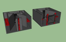
I invested some free time to model the Paraflex TOP using hornresp Compound Horn Model CH2 released some months ago. It should give a good approximation once we can't have a perfect model considering this particular design but even using CH2 the results is very different from what people have been measuring.
Any thoughts to improve simulation?
Main differences between model output and measurements:
Note: Due to shared holes between H2 and H4 segments, the H2 segment was simulated as constant CSA.
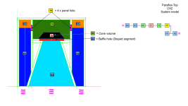
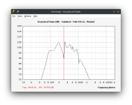
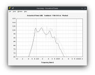
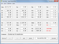
Attachment#1 - Proposed Hornresp Model
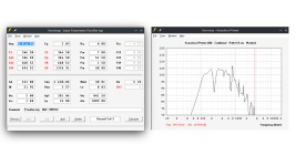
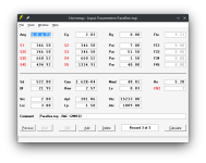
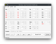
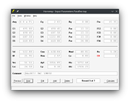
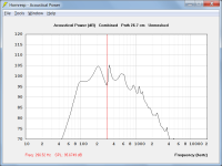
Attachment#2 - Hornresp inputdata and SPL based on latest drawing version G#1
Attachment#3 - Latest drawing
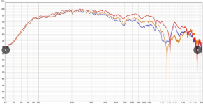
Attachment#4 - SPL measruments 1
Attachment#5 - SPL measruments 2
Attachment#6 - Hornresp inputdata txt
I invested some free time to model the Paraflex TOP using hornresp Compound Horn Model CH2 released some months ago. It should give a good approximation once we can't have a perfect model considering this particular design but even using CH2 the results is very different from what people have been measuring.
Any thoughts to improve simulation?
Main differences between model output and measurements:
- Left knee at 117Hz while measurements shown at 90Hz
- Big SPL dip at 235Hz and 709Hz while measurements shown 1st dip at 1400Hz~1500Hz
Note: Due to shared holes between H2 and H4 segments, the H2 segment was simulated as constant CSA.
Attachment#1 - Proposed Hornresp Model
Attachment#2 - Hornresp inputdata and SPL based on latest drawing version G#1
Attachment#3 - Latest drawing
Attachment#4 - SPL measruments 1
Attachment#5 - SPL measruments 2
Attachment#6 - Hornresp inputdata txt
Attachments
-
 Paraflex-top-System-Model1.png16.6 KB · Views: 286
 -
 Paraflex-top-System-Model2.png29.8 KB · Views: 240
 -
PFX 1x12 top-150mm-FINAL.pdf4.6 MB · Views: 116
-
 PARAFLEX 1x12 Kick-Top G1V2 Free Plan CC - measurement.png142.9 KB · Views: 227
 -
 PARAFLEX 1x12 Kick-Top G1V2 Free Plan CC - measurement2.png147.3 KB · Views: 224
 -
Paraflex-top.txt2.7 KB · Views: 59
Hmm, no experience yet with all these funky new multi resonant alignments, so at a glance can only point out that based on published specs the upper mass corner dip is at ~Fhm = 2*Fs/Qts = ~558 Hz and Vc corner where its pistonic BW morphs to its TL modes BW is at ~34400/pi/7.6 = ~1441 Hz, so near enough 'dead on', clearing up two notches.........
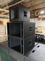
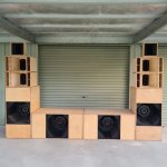
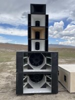
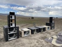
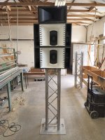
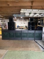
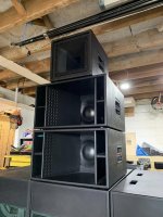
What is a Paraflex TOP?
A loudspeaker box to reproduce audio signal !!!
Attachments
-
 363429670_6421811134551562_5261154221538792844_n.jpg334.2 KB · Views: 107
 -
 363429419_6421811231218219_9045746442316232088_n.jpg299.5 KB · Views: 99
 -
 363422823_6421810731218269_4886861298487527118_n.jpg600.2 KB · Views: 97
 -
 363422799_6421810784551597_1259367337064379836_n.jpg376.4 KB · Views: 91
 -
 363420330_6421811274551548_4267055084675805905_n.jpg373.6 KB · Views: 87
 -
 363419647_6421810591218283_1298362807537590832_n.jpg414.3 KB · Views: 101
 -
 363418677_6421811074551568_424475238787532657_n.jpg272.2 KB · Views: 88
 -
 363416972_6421811461218196_13475789957492159_n.jpg245.8 KB · Views: 101
 -
 87511494_2734316869967692_7249746040771837952_n.jpg37 KB · Views: 100
Thanx. The visualization gives an idea, do you have a drawing?
Yes, 1st post, Attachment#3 , it's a PDF file.
Any thoughts to improve simulation?
https://www.diyaudio.com/community/threads/hornresp.119854/page-698#post-7453002
Reviewing the Throat Chamber data:
Net Volume = 33cm x 17cm x 33cm = 18513 cm³ = 18,5L
Air volume occupied by the driver according to B&C data sheet = 3300cm^3 = 3,3L
Throat Chamber Volume (Vtc) = 18513 cm³ - 3300cm^3 = 15213cm^3 = 15,2L
Throat Chamber Cross-Sectional Area (Atc) = 33cm x 33cm = 1089cm^2
Throat Chamber Port Cross-sectional Area (Ap1) = 4 holes with 8cm diameter = 4*0,25*pi()*(8cm)^2 = 201,06cm^2
Throat Chamber Port Lenght (Lp) = 1,5cm (wood thickness)
Reviewing the Rear Chamber data:
Rear Chamber Volume (Vrc) = In this case it's basicaly the volume of air inside driver cone = 2000cm^3 = 2L
Rear Chamber Average Lenght (Lrc) = Vrc / SD = 2000cm^3/522cm^2 = 3,8cm
H3 CSA also corrected from 660,52cm^2 to 522cm^2
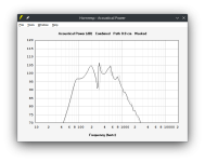
Attached the results with updated data. The big dip still there, the overall SPL curve is now more smooth.
Attachments
The big dip still there
But the reason for it being there has changed - it's now because Lp has been reduced from 33 cm to 1.5 cm.
But the reason for it being there has changed - it's now because Lp has been reduced from 33 cm to 1.5 cm.
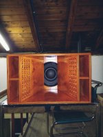
Yes, what is intriguing me a lot is why the real measurement do not show the dip, maybe the small horn in front of the driver is improving the frequency response like phase plug?
Also once off-set in general introduced reflections and dip in the frequency response, simulated the hole as a slot close to the wall in order to make L12 basically 0, so no off-set horn, the improvement was very minimal as can see in the attachment.
Attachments

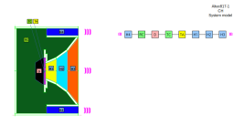
I just modify the Altec817 box style to get single driver installed as the Praflex Top and the external dimensions were adjusted to match Paraflex Top:
H=600
D=600
W=330
The central Horn has the same length and throat. The month are slitly different. Diving central horn by 1 or 3 segments doesn't shown much difference.
The chamber between driver and central horn are also at the same size and the other chamber and horn are different but were adjusted to deliver the closest response as possible.
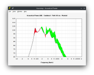
The last attachment shows the SPL comparisson between those two design with colored area:
GREEN = Paraflex present Higher SPL
RED = Altec Present higher SPL
The driver used in the simulation is the same.
Altec817 does not show have the dip in the frequency response but deliver lower SPL response in 50% on the frequency response.
H=600
D=600
W=330
The central Horn has the same length and throat. The month are slitly different. Diving central horn by 1 or 3 segments doesn't shown much difference.
The chamber between driver and central horn are also at the same size and the other chamber and horn are different but were adjusted to deliver the closest response as possible.
The last attachment shows the SPL comparisson between those two design with colored area:
GREEN = Paraflex present Higher SPL
RED = Altec Present higher SPL
The driver used in the simulation is the same.
Altec817 does not show have the dip in the frequency response but deliver lower SPL response in 50% on the frequency response.
Attachments
-
 SPL comparison - Paraflex vs Altec817-2.png16 KB · Views: 73
 -
 SPL comparison - Paraflex vs Altec817.png16.3 KB · Views: 70
 -
 Hornresp - Input - no-offiset.png16.8 KB · Views: 62
 -
 Hornresp - Input - Altec817.png16.6 KB · Views: 72
 -
 Altec817-1.png11.9 KB · Views: 77
 -
 Altec817-1-System-Model.png14.4 KB · Views: 88
what is intriguing me a lot is why the real measurement do not show the dip
I don't understand it either.
If your corrected CH2 Paraflex TOP is simplified down to the CH design shown in the attachment, the results are almost the same even though they are calculated using a completely different model. This would tend to suggest that there is nothing wrong with the CH2 simulation model, particularly as CH results have been validated on numerous occasions in the past.
About the only other thing that could be done would be to specify a path length of 26.7 cm, the distance between the centre points of the two outputs. This reduces the dip a little, but does not remove it completely.
Another of life's little mysteries it would seem...
") .
.Attachments

Perhaps this is the secret to the Paraflex TOP design...
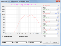
True, in additional I would say that not knowing the amount of smooth they apply on the measured signal it could mask the dip as well. But adding filling could be a nice model approximation.
While inside Loundspeaker Wizzard I was able to apply the filling and clicked on save button. Exported txt file to check again and filling data was there as indicated below. But clicking on CALCULATE button the filling is not being take into account in the simulation. Is it another bug with linux or it works only inside Loundspeaker Wizzard for CH2?
|ABSORBENT FILLING MATERIAL PARAMETER VALUES:
Fr1 = 0.00
Fr2 = 4000.00
Fr3 = 0.00
Fr4 = 4000.00
Tal1 = 100
Tal2 = 5
Tal3 = 100
Tal4 = 5
Thank you David.
But adding filling could be a nice model approximation.
It would be interesting to know the intended purpose of the holes.
The designer obviously included them for a reason, and presumably not just to make the system look nice
.Is it another bug with linux or it works only inside Loundspeaker Wizzard for CH2?
The absorbent filling material feature only works with the Loudspeaker Wizard, but applies to all configurations, not just CH2.
It would be interesting to know the intended purpose of the holes.
Yes, for sure. Don't know exactly who create this design for the first time, but MMJ for sure know. Unfortunately I haven't seen here for long time, will try to bump him in another thread, maybe he shows up.
If it was a electrical circuit I would say that while filling in general would increase "resistance" those parallel holes for sure would reduce the "resistance".
If it was a electrical circuit I would say that while filling in general would increase "resistance" those parallel holes for sure would reduce the "resistance".
That is indeed the "interesting" bit
.- Home
- Loudspeakers
- Multi-Way
- Hornresp model for Paraflex TOP