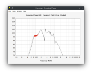
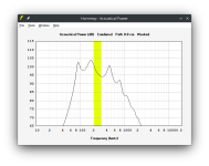
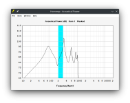
May be it's too simple and I'm totally wrong - but I'd assume the 200-300Hz-dip to be caused by a phase-missmatch between front and back emmitting waves from the driver.
By adding absorbent filling material to the two (back-wave) channels, the respective sound level is attenuated and consquently the dip diminishes. As a tradeoff, the acoustic power below 200Hz of the entire system is going down as shown in post #16.
My best guess would be, that the holes at the end of the 'BR-channels' just smooth our the phase difference between front- and back-wave as the channel lenghts / end of channels are not that strictly defined to one point any more. However, by adding holes instead of resistance you do not lose sound pressure (beside still existing phase-mismatch).
Do not know how to simulate this with hornresp though.
How do little holes affect freqs with 1/4 wavelengths 20-30cm long ? I (maybe)think it’s just cosmetic at this point, but these designs are constantly battling the front/rear output phased conundrum and bazillion resonances(and cancellations ) created by front and rear resonators of oddball shapes and path lengths ?
patrick Sander knows these designs better than anyone in that FB group it seems.

patrick Sander knows these designs better than anyone in that FB group it seems.
Last edited by a moderator:
How do little holes affect freqs with 1/4 wavelengths 20-30cm long ?
I expect the constricted areas are creating some mass-loading.
A constricted terminus is a given for any Voigt, Scott uses a choke (borrowed from Paul Klipsh). They affect the bass.
It is easy to imagine it might well have somethign to do with the discrepancies noted.
Does someone have one they can measure so we better know th emeasure condiitons. Also allows for some experimenting. For instance close off some holes or add some damping and see what changes.
dave

One could ‘adjust’ those holes as needed to fix the 3x Fb area where the resonators ‘over/under lap’ maybe?
(generic pf subwoofer example)

(generic pf subwoofer example)
Last edited by a moderator:
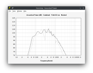
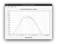
Adding a small amount of absorbent filling material at the mouths of the two outputs in the corrected CH2 design to take into account the resistive holes, improves the response significantly.
Perhaps this is the secret to the Paraflex TOP design...
Indeed, this appears to be just a proper acoustic solution to my long ago 'cheating' open cell foam extensions to quell horn mouth eigenmodes/reflections back to the throat, smoothing 'X' BW response based on mouth/baffle size with minimal output reduction at typical listening distances, so assume an extra horn segment or terminus/mouth option adding this acoustic 'screen' is required.
No clue about this particular design, but like Dr. Geddes' foam horn insert, make enough of the right hole size/spacing and mouth horn area to mimic it and it moves to near enough ~aperiodic, so may very well be these otherwise very limited BW speaker's 'saving grace' for < extreme far-field apps.
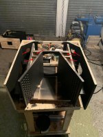
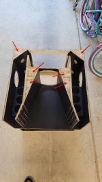
Well, according to the images given in the pdf in the first message of this thread, these are are a lot of holes (40 per side) and not too little from my point of view:How do little holes affect freqs with 1/4 wavelengths 20-30cm long ?
May be covering 10-15% of the surface of the 'BR'-channel. Seems not that insignificant to me. The hole-area roughly covers 20% of the 'BR'-channel and connect the front horn with the BR- or rear-channel.
As the front area of the BR-channel is norrowed by the perforated board, it might add some acoustical resistance. However, as the majority of the BR-channel is still open I'd assume this will be not too much.
May be it's too simple and I'm totally wrong - but I'd assume the 200-300Hz-dip to be caused by a phase-missmatch between front and back emmitting waves from the driver.
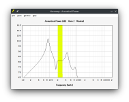
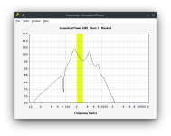
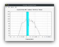
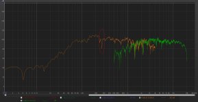
Yes, you are right, in general for any compound loudspeaker the phase and amplitude between the outputs is are the issues, take a look below:
Attachment #1 = Paraflex TOP - Side Horn SPL output stand
Attachment #2 = Paraflex TOP - Central Horn SPL output stand alone
Attachment #3 = Paraflex TOP - Combined Horn SPL output
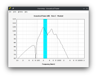
Attachment #4 = Altec817 - Side Horn SPL output stand alone
Attachment #5 = Altec817 - Side Horn SPL output stand alone
Attachment #6= Altec817 - Combined Horn SPL output
If you compare Paraflex TOP with Altec817, they have basically the same central horn but the side horns and chamber are very different affecting more the output form the side horns. So the Paraflex model as CH2 present more miss-match between central and lateral horn. For sure that path is the key to improve the SPL response in order to remove the dip.
If you also check the Attachment #7 you will see colored in light blue that the and of the side horn narrows, while only pink and orange are constant cross-sectional area, but Hornresp model CH2 offer 2 segments, so we can't simulate precisely that effect but tryng to check the effect I reduce the S3 area in the model as you can see in the attachment#8 to see the trend and the attachment#9 show that changing S3 you basically loose low frequency amplitude because we are reducing volume from the side horn that is more responsible for the low end response.
Attachments
-
 Paraflex-top5.png15.9 KB · Views: 85
 -
 Paraflex-top4.png7.7 KB · Views: 79
 -
 Paraflex-top3.png4.7 KB · Views: 78
 -
 Altec817 - Combined Horn Horn 1 and 2 Output.png15.1 KB · Views: 85
 -
 Altec817 - Horn 2 Output.png15.1 KB · Views: 85
 -
 Altec817 - Horn 1 Output.png15.4 KB · Views: 87
 -
 Paraflex TOP - Combined Horn 1 and 2 Output.png15.5 KB · Views: 82
 -
 Paraflex TOP - Horn 2 Output.png15.5 KB · Views: 78
 -
 Paraflex TOP - Horn 1 Output.png15.5 KB · Views: 79
There is another Paraflex TOP with single side horn, the measurements shows the dip. Probably more narrow compared what i would expect from the simulation.
Attachments

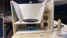
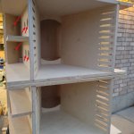
There is also Paraflex Top model that they add one extra panel in the side horn with holes and also make holes in the side panels to create a second chamber, a kind of Stubbed design. They fill those chambers with fiber as you can see in the attached images. Probably the dip is there and they are tring to improve the response in some way. This looks to be the older version once the PDF I posted is the most updated design without those stubs.
Attachments
-
 363417529_6421810127884996_9022168203346048569_n.jpg164.5 KB · Views: 109
 -
 363421168_6421810254551650_8886751590901468212_n.jpg360.4 KB · Views: 107
 -
 363422375_6421810214551654_617363122293834337_n.jpg296.4 KB · Views: 107
 -
 363423794_6421810977884911_8658618416710908981_n.jpg363.2 KB · Views: 99
 -
 363427886_6421810301218312_6474052948036808305_n.jpg258.8 KB · Views: 104
Looks like the most updated drawing is the one with absorbent material and stubbed chambers as attached.
I was doing additional comparison with other designs and from my point of view the complexity and the risk for peaks and dips in the SPL curve doesn't worth the effort to improve simulation nor to build this design.
Attached you can find two comparisons:
Paraflex Top vs Front Load Horn with sealed chamber (exactly the same volume and dimensions 600x600x360 = 130L)
Paraflex Top vs Front Load Horn with vented chamber to reinforce low frequencies, it may requires an extra 10L but goes lower in frequency range.
Attachments
What was the final hornrep config you went with?
To define a reliable model it would require build boxes but at the end I didn't like the response and the involved risks to model accuracy, so I moved to a different design using front load Horn with vented chamber to improve cooling and found better SPL for the same box volume.
You can find some usefull discussion in the thread below:
For Eminence's Delta 10A - say either a mini-La Scala ~ 15" cube or a "C" horn. If you've something in this ballpark I'd like to see the plan. Simpler is better.
just like to have a fun toy - one of Dr. Edgar's first Speaker Builder Magazine's articles concerned a folded midhorn.
just like to have a fun toy - one of Dr. Edgar's first Speaker Builder Magazine's articles concerned a folded midhorn.
- freddi
- Replies: 106
- Forum: PA Systems
In addition, the group delay for this paraflex dons't look good, pay attention on that variable if you consider this model in your analysis.
Lordsansui,
Hello! It has been a long time. 😀
I hope you are well and enjoying the holiday season. 🙏
I am not sure what is going on in your simulated model but in our real world testing of the G#1 1x12 Kicktop we did not have any response notch around 300hz. There were no problems around 300hz, however, we did experience notches up around 500hz and another falling within 750hz to 800hz which upon investigation we discovered were being caused by odd-order harmonic resonances produced by the cabinet's Low-Tuned Resonator (LTR) section interfering with the output of the midrange horn (HTR flare section) so that is why we included the band-stop filter chambers (with some damping material in them) placed in the LTR section to tame the harmonics which in turn alleviated those notches caused by the interference.
It took many experiments, revisions, and sawdust in order to finally finally have a satisfying result (and various methods were tried). There were several people participating in the effort.
This updated design is our HOQS Paraflex Type G#1 V2 style 1x12 Kicktop (note that the "G" stands for global since people from many different locations around the world helped with this) .
We provided multiple measured comparisons of previous revisions versus the V2 release and the improvements around 500hz and around 750hz are apparent along with a little more bottom-end due to making more cabinet volume available to the LTR section. 🙂
You can see these comparison charts along with a few others in the media section of this post (link below):
https://www.facebook.com/groups/bassaz/posts/7132254903456242
Here (below) are some of the comparison charts .... Each set is measured under the exact same conditions (sensitivity is not calibrated, but the settings remained the same for each pair of measurements which is what is most important for comparison purposes).
Last edited:
- Home
- Loudspeakers
- Multi-Way
- Hornresp model for Paraflex TOP