NAD 521 with "audio modification"... worth buying?

Hello everyone,
I need a bit of advice. I have the opportunity to buy a NAD 521, which was revised and got an "audio modification" in 2015. The seller asks for €75, with p&p I will end up at around €85 (roughly $90). Its unclear what this "audio modification" means, the seller does not know. I attached a picture from the PCB. The Display looks rather dim on the pictures the seller provided.
Is it worth it? Ist the price okay? The device itself looks very clean and without any damage. I know there are quite some versions of the 521 around, with the plain 521 being the oldest. Should I look for a 521 BEE, which will be around €200 in my area?
I am looking for an affordable, good looking "vintage" CD Player with robust mechanics which can be upgraded with better components. The motivation to do this is more to learn a bit and just for the fun of modding. I do not expect to create something real high-end.
Cheers, Robert
Bildschirmfoto 2025-01-06 um 14.09.46.png

Hi from a new DIYer

I'd rather build than buy. I'm currently working on an SP-14 preamp from Vacuum Tube Audio and a Gainclone. After those are finished my signal path will be entirely home built other than the SL1200 (which is not without mods). I'm looking forward to seeing what everyone else is working on.

Here's a dual mono Emerald phono preamp from RJM audio that I recently built. The chassis were old serial KVM switches with some figured maple to add some flare.

20250108_164516.jpg


20250108_164601.jpg

Hello World

Hello all,

I'm Kalle from Germany; event technician and building bass cabinets since the early 90s or so...
Bought AJhorn last year and am now mostly using Hornresp instead ;-)

Thanks to this forum and others I built two 15"-tapped horns last year which work very good. Next project are some 18" br/TL-horn-hybrid speakers.

Greetings!

Kalle

7.4V (5V) Battery Power Supply with Aliexpress parts

Hello, recently looking into all sort of battery power supply solutions

for starting out and getting some kind of reference to go from i wanna build something similar to this one: https://www.aliexpress.us/item/1005005947064087.html for 5V output

consisting of these parts:
https://de.aliexpress.com/item/1005005965787184.html (outputting 5V)
https://de.aliexpress.com/item/1005006246781194.html
https://de.aliexpress.com/item/1005007103958671.html
https://de.aliexpress.com/item/1005005727166588.html
4x Molicel P26A 18650 Cells in 2S2P configuration
2 Switches (like the LHY power supply), one for charging one for load

gathering mainly from google or youtube this should work out just fine 🙂

Speaker fell over, now not working. Help

Hi guys. I have a pair of Townshend Glastonbury speakers from the 1980s. They have been in regular use with no problems.
Well I accidentally nudged one of them and it fell over on its side onto a wooden floor.

The ribbon tweeter still works but the midrange doesn't. I believe it is a Jordan J125 or J150. What should I be looking for? I have the crossover and the driver unscrewed but can't see any dislodged wires. The crossover board seems intact.

What should I be looking for?
Thanks, Stephen

AD1862 vs AD1865

I have a ANK DAC 4.1, which uses a CS814=>AD1865 implementation.
The cheap USB input board failed, so I was planning to replace it with the XMOS based I2SoverUSB board.

But I also thought.. since I am at it, why not replacing the whole DAC board with a XMOS => AD1862 implementation.
The new design would use dedicated separated supplies for the digital and analog sections, and the outputs of the DAC chips would be directly connected to the I/V transformers that drive the original tube output stage, as per original audio note design.

Long story short.. anyone who has experience playing with the AD1865 and AD1862 would suggest one over the other?

Thanks,
Marco

Save your Transformer, always use an Artificial Center Tap on your heater windings...

Greetings, friends. Today I was hoping to spark a brief discussion on proper heater wiring. This idea came from an Instagram poster known as Amptech74 who repairs guitars and tube amps and probably seen more violently explosive tube behavior than most of us in Hi-Fi land, with the notable exception of @Tubelab_com.

Anyway, here's the idea: don't use the Center Tap that's hardwired into the power transformer. When a power tube fails, the plate voltage is going to find the easiest path to ground. If the plate arcs to the cathode, it still has to go the cathode resistor to get home, but if it arcs to the heater, it only has to fight the resistance of the copper wire. If that voltage happens to pass thru the power transformer, well, there's gonna be damage. But if you are using an artificial center tap, the HV can only cook those 2 resistors, saving your expensive iron.

So. Waddya think?

w

Hello from new member in NJ

Hello. I am actually an old member of diyAudio but I stopped pursuing this passion for > 10 years and I am not able to recover my old account here. I am a EE nearing retirement age. Most of my career has been spent working on Naval aircraft engine controls with focus on software and electro-mechanical systems. My circuit design knowledge is circa 1985. I was also a dedicated speaker builder for close to 20 years but also stopped that when family and job started taking most of my time. I am getting back into this hobby with plans to recap/revive an Apt Holman One amplifier and some Soundstream D100 and D200 car amplifiers. Hopefully, I will have some knowledge to contribute as I get more involved.

Upgrade from here

Hey everyone. I do live sound production and provide sound for both DJs and bands in many different indoor and outdoor venues. Anywhere from 100-1000 people.

I’m looking for a PA that can accommodate these shows with good results.

I’ve used some of the upper end of the prosumer market in the past and although had decent performance was not quite able to hang at larger events.

I’ve had Yamaha DZR 12s and had them hitting limit at larger shows. I also had one of them die during a show and ended up having to send it in for repair of a blown transformer on the board. A friend of mine also has owned dzr 10 speakers for monitors and has had to send them both in for repair of similar issues. Great warranty but need better reliability than this.

So what’s considered the next step from here? Something over a the DZR SRX series that can push a bit harder and not cost triple the price?

Is it possible to get better than this without spending that much more or does the price just go up significantly after this point?

I’m open to powered or passive options whatever will get the job done best.

Thanks for reading and I appreciate all of your input.

“Bumpy” or Variable Depth Driver Chamber - Method?

Several times I have seen Scott and others recommend certain optional improvements or tweaks for speaker enclosures, one of which applies most commonly to back horns with shallow driver chambers. The idea is to move the rear surface of the driver chamber backwards (making the chamber deeper) but then displace the extra volume with many blocks of various lengths of wood, randomly, so that the rear chamber wall becomes “bumpy” but the chamber volume remains the same as the specified chamber volume.

For the life of me I cannot recall what this is commonly referred to as, and I am therefore having difficulty finding the method to accomplish this accurately. I would obviously begin by calculating the volume of the standard driver chamber (as designed). Easy enough. What is the simplest method to achieve the desired result?

Need help about filament noise

Hi . I have a sharp md-xv300 . Original transformer is dead . I replaced a transformer all voltage needs is same except that original transformer has a separate 30v for running filament screen . I have extra pins with 12v and also 25-0-25v that used to run amplifier chip. Screen works with both on 12v i have very load noise and low light screen and on 25v screen brightness is ok but it has also noise but lower . I'll be thankful if there is a solution to solve or reduce noise . Thanks 🙏

For Sale Geloso G-227A EL34 PP mono amplifiers

A few months ago, I came across a beautiful set of Geloso G-227A tube amplifiers and felt inspired to breathe new life into these rare gems. After a careful restoration, I’d say they’ve come back to their full glory!

I’ve restored them with precision—replacing old capacitors and resistors, adding modern RCA connectors, and upgrading to contemporary speaker terminals. Their vintage casings remain beautifully intact, with just a touch of wear that gives them that authentic retro vibe.

Result is a dynamic and detailed sound thanks to fine-tuned gain stages and high-quality transformers. Powered by brand-new RFT EL34 tubes, they offer a great listening experience.

There is a switch that bypasses all the controls and you can use them as power amps. If in another position, you can use them with their original inputs.

Price is 1100€. We can negotiate and I do accept some trades. Location Croatia.

Regards

Attachments

  • 3_with_bgc.png
    3_with_bgc.png
    1.3 MB · Views: 817
  • 4_with_bgc.png
    4_with_bgc.png
    1.4 MB · Views: 626
  • 7_with_bgc.png
    7_with_bgc.png
    1.8 MB · Views: 693
  • 1_with_bgc.png
    1_with_bgc.png
    1.9 MB · Views: 141

Shanti Dual LPS 5V/3A , 5V/1.5A

Hello ladies and gents.


Music and linear power supply has been always a good match . The main problems of LPS is extremely inflated pricing and no data.


You see not all LPSes are equal . Just using a transformer will not automatically give you a better PSU. Worst is that most of manufacturers include no testing . no data that can help chose one.


We mean to change that.


First we started with the transformer . There are many types of transformer , some are worst than others (noise coupling , electromagnetic interference)

We chose one of the best transformers for noise ,r-core


The transformer has a dual output (galvanically isolated ) so you can power multiple devices (RPI + dac , Katana , etc) and we used independent (of course since they are isolated) filtering on each rail. First a capacitance bank (massive) to reduce the 50/60Hz noise , then a active filter , fallowed by an LDO to keep voltage stable . Since LDOs have poor transient and impedance , we used a last active filter (with good transient) and then capacitance but most importantly , super capacitors on the output . So all power comes in fact from supercaps..So yes , transients and impedance of the LPS is..good.


Of course , Shanti includes AC line filter and AC is earthed to casing.


A few words on what we achieved . Measuring noise (in real word scenario) we see about 80nV (0.08uV of noise from 0-20Khz at the floor of our AP machine. This is comparable to batteries from our internal testing .


As explained , Shanti is not only shining because of the ultra low differential noise, but also because of incredible low impedance / deep reservoir of electrons at the output of the PSU ( thx you soundcheck for your suggestions )


At last ... pricing . We are working very hard to make this LPS the lowest priced on the market . All components are on the way , it will take a few weeks to start accepting orders. Questions and comments are welcomed

Attachments

Insulators for parts passing through aluminum heat sink? Bolts for TO3 devices?

Hello there,

I get that you use a TO3 insulating pad under a TO3 device so you don't short it out to a heat sink if it is mounted on top of one, but what insulators do you use around the leads/bolts passing through the heat sink?

What type of fasteners are commonly used?

What would be a a good "broad" insulator to use between the board the the heatsink?

Here is an example of what I am talking about,

Thank you,

David.

Attachments

  • Quad 606 board trans mounted.jpg
    Quad 606 board trans mounted.jpg
    96.4 KB · Views: 195

Pass Labs X1 volume control probelm

I have a Pass Labs X1 preamp, and I’m currently facing an issue where, at volume level 3, the left channel suddenly goes to maximum loudness. During troubleshooting, I swapped the volume control board with the right channel, and the problem followed the board. This confirmed that the issue lies with the volume control board.


After further testing, I identified that Q3 on the board is the faulty component. It’s marked as “8F” and comes in an SOT-23 package. However, I haven’t been able to find much information about it. Could you help identify the exact part number for this component?

C3850 Little construction project

I have been building a little pre-amp from an eBay pcb which is based on a 3850 circuit been going well and have fitted it into an old NAD chassis and using f the NAD volume pot. Which turned out to be way too low at 20kohm. I tried replacing the 5532 with a 4562NA however this oscillated producing a ticking noise. the 5532 was tick free. I added 47k in front of the pot to give it some actual volume adjust ment but I may need to change it for a new one. At the moment I have a 50hz hum issue to deal with once the volume heads towards 1/3rd I am wondering if this is the filtered iec I let at the moment. But hum aside it does sound very good way better than my old cyrus

Attachments

  • IMG_2696.jpeg
    IMG_2696.jpeg
    1 MB · Views: 160
  • IMG_2697.png
    IMG_2697.png
    621 KB · Views: 152
  • 7401F3E8-C9F3-4C5E-9CB0-055E8F3F8B31.jpeg
    7401F3E8-C9F3-4C5E-9CB0-055E8F3F8B31.jpeg
    491.7 KB · Views: 153

2 TKD (big) potentiometers, 50K log taper .

Hi. I have a couple of pairs of the gorgeous TKD 50k mono potentiometers (Volume controls) for sale. These were used in a volume control shoot-out in a multi channel system. They are in near mint condition. The input, output and ground connections have been carefully desoldered and cleaned. I would like $85/ pair, shipping in USA included.

Attachments

  • 0FC2AAE4-CBF1-4A75-8D5D-582A00F5DA7E.jpeg
    0FC2AAE4-CBF1-4A75-8D5D-582A00F5DA7E.jpeg
    507.7 KB · Views: 274
  • 31530EDC-F385-486B-AE6C-4AA24FD03D73.jpeg
    31530EDC-F385-486B-AE6C-4AA24FD03D73.jpeg
    318.1 KB · Views: 276
  • 5EFE5CBD-BE78-469C-B281-CC30B4156C5F.jpeg
    5EFE5CBD-BE78-469C-B281-CC30B4156C5F.jpeg
    403.9 KB · Views: 265

Replacing pots in Infinity RS-II crossovers

Hi all, quick question. My crossovers have 2 pots each to adjust highs and mids. One of the mids pot is completely shot and the other one reads funky. Tweeter pots seem OK but they're 42 years old.

According to schematics, all pots are 5 ohm 5 watt:

RS II technical manual.jpg


But in real life, they're clearly different. Folks say the mids pots are 15 watt and the tweeters 5 watt, and that looks plausible:

pots.jpg


My first thought was to just replace the old pots... but audio grade 5 ohm 15 watt pots only appear to exist in Australia

So now I'm considering replacing them with fixed resistors, since their utility is debatable to begin with.

I tested them (out of circuit):
  • Tweeter pots measure 2.5 ohm at midpoint and 5 ohm all the way down, so that's all good per specs
  • The one mid pot that sort of still works measures 3.4 ohm halfway, and 5.7 ohms all the way down. The other mid pot is too far gone to measure anything.

Now for my questions:
a. That mid pot's 3.4 ohm halfway to 5 ohm read doesn't match a known taper. Is it fair to assume it was linear when new, and it just drifted over the decades?
b. I want a "flat" response, so I'm thinking 2.5 ohm fixed resistors (assuming those mids pots are in fact linear). As far as power rating, it's tough to find 5 and 15 watts in the same series but Dayton makes 2.4 watt, 1% wirewound rated 10 watt and 20 watt, so I'm leaning that way and it won't break the bank. Still, it would mean a significant increase in power rating over stock
c. I've done a bunch of reading about whether increasing resistors' power rating can affect sound quality, and the consensus seems to be that it won't make it worse and it might even make it a little better. Do you guys concur?
d. Now we're splitting hairs, but I gotta ask: my new fixed resistors will probably have much lower inductance than the pots they replace. Does that mean anything in terms of sound quality?

Thanks!

2SC5200 fake or original?

According to the seller only tray pack has 'Japan' marking on 2sc5200/1943 transistors & there is no mention of 'Japan' in the strip pack(see attachment). I believe these are 100% authentic, what do you think? 🙂
Best Regards!

Edit:- These aren't original but good quality chinese copies. My apology to everyone.

Attachments

  • FB_IMG_1638263085197.jpg
    FB_IMG_1638263085197.jpg
    66.5 KB · Views: 1,122
  • FB_IMG_1637922393308.jpg
    FB_IMG_1637922393308.jpg
    45.1 KB · Views: 1,609
  • IMG-20211126-WA0000.jpg
    IMG-20211126-WA0000.jpg
    59.6 KB · Views: 1,053
  • Like
Reactions: asuslover

Common Ground Collector amplifier

In 2017, I built this amplifier for my brother's audio system. It is a single common grounded collector amplifier based on RMX series of QSC.

Supplied with +/-80V, I added five pairs of transistors for output stage. It is very stable once the bias adjustment is set properly. The input opamp is very important to be good quality and check +/-15V rail supply to be as simetrical as possible. I wanted to keep the same subsonic filter to cut off frequencies under 30Hz and 50Hz.

The sound is very good however I was designing a PCB with smaller size. Thanks

Attachments

  • 1736241908159.jpg
    1736241908159.jpg
    64 KB · Views: 220
  • 1736241919037.jpg
    1736241919037.jpg
    84.5 KB · Views: 187
  • 1736241914986.jpg
    1736241914986.jpg
    26.1 KB · Views: 95
  • 1736241930355.jpg
    1736241930355.jpg
    83.1 KB · Views: 87
  • 1736241923626.jpg
    1736241923626.jpg
    63.6 KB · Views: 220
  • Like
Reactions: luis401

Onkyo Integration TX 870 issues.

Hello. I’m working on my TX 870 and having a few issues. The left channel dropped out and the main fuse blew. I found a cracked bridge rectifier and it was toast. Replaced it along with all the outputs on the left channel. Found some bad transistors on the main board and also replaced the drivers. For some reason I’m getting full rail voltage at the VCT test pin. This won’t allow the protection circuit to close the relays. It should be in the millivolt range. The right channel is fine. DBT goes bright as the main power relay closes and then opens and the DBT goes dim. Constant cycle. I’ve got the service manual and have replaced the emitter resistors, and several other bad components that tested bad. Any ideas ? The output transistors are fine. No shorts. Thanks in advance. The only other thing I replaced were the 2 caps in the protect circuit.

looking for info from diy member featured on youtube

hi forum
i've just watched a video on the steve guttenberg youtube channel featuring a gentleman called joe who is into horn speakers, he referenced this forum in the video.(the video is from 5 years ago)
in the video he briefly touched on the design of his subwoofers, which use two speakers working opposite to each other and facing in opposite directions. i'm hoping that this subject has been discussed already and that someone could point me to the correct thread, or even plans and theory for this subwoofer.
this is the video -- Login to view embedded media
any info is appreciated
gaz

Single drive full range: the bug has bitten

Hey everyone, brand new member here who will probably leech more information than contribute given my complete lack of electrical/acoustic intellect (drummer, go figure). In fact, I never thought I'd be reading much less typing messages to this group since I've always been an OOTB audiophile musician gear-collecting type, albeit single-driver-curious, but that seems to have changed last week:

  1. Finds pair of Fostex fe206e-loaded cabinets for $100 on fb marketplace and says screw it why not
  2. Plugs them into garage "tester" setup (Arcam receiver, Meridian Explorer portable dac), sounds like crap
  3. Removes the reflex port to discover there's some sort of crossover network thing, bypasses it, listens again, ok now we're going somewhere interesting
  4. Swaps them into the Rogers LS3/5A livingroom setup (Naim entry-level separates, Bel Canto 1.5 dac), and despite flaws, there's something alluring that bears more exploration
  5. Swaps them into "reference" DeVore Gibbon Super 8 system (Naim Supernait 3 integrated w/ HiCap DR, Rose RS150b streamer/dac), hasn't left chair for 5 hours (other than to make dozens of adjustments to speaker/listening position). Oh, and signs up for diyAudio account 😉

Wow. As absurdly, unfathomably finnicky as these things are about placement and amplification/sources, there is a magical palpability and image that, until now, I've only heard others talk about with their setups, or have only heard myself on (some but not all) six-figure setups at shows.

So, this is all to say I forsee myself spending hundreds of hours scouring this forum for tweaks and advice, of which there appears to be no shortage of, and will thank you all in advance for your volumes of reference for this strange and beautiful new world. Well, not always beautiful since function>form is why we're all here 🙂

Oh, and speaking of which, whoever made my cabinets actually did an impressive job making their fit and finish as furniture-grade as possible. Beveled edges, invisible joins, nice (cracking, will need restoration) veneer finish, black platforms...real classy work. Would love any information anyone may have on them (and of course, modding pointers to help me navigate the sea of information that is this forum)!

Attachments

  • 1000035835.jpg
    1000035835.jpg
    112.1 KB · Views: 207
  • 1000035836.jpg
    1000035836.jpg
    144.9 KB · Views: 196
  • 1000035838.jpg
    1000035838.jpg
    81.7 KB · Views: 194
  • 1000035839.jpg
    1000035839.jpg
    144.8 KB · Views: 211
  • 1000035916.jpg
    1000035916.jpg
    237.4 KB · Views: 216
  • 1000035834.jpg
    1000035834.jpg
    222.5 KB · Views: 214
  • Like
Reactions: Vix and wchang

Match equal loudness graph when designing a sub?

When designing a sub should I aim to get the SPL graph to match the equal loudness curve? That's what I was doing initially while trying to design something useful for a cheap driver. I didn't have much hopes for this driver, but found a design that should work well. It matches the equal loudness graph from 27-80Hz for 60dB listening. I wanted to compare its simulated performance to something, and having looked up a 15" Hsu sub, they show a mostly flat graph that slopes down as the frequency decreases. They should know what sounds good, so am I doing it wrong?

1733355146928.png

Fixed gain field recorder?

Do you think we have come to a state where we could build a field recorder without a gain knob. I am pondering if we have the noise levels and dynamic headroom in both analog and digital domains that we could just set a gain and live with it for any recording really.

Prerequisite is perhaps mic sensitivity and noise figures... I'm thinking really serious state of the art recording like organ in church, closed mic guitar amplified small jazz club etc. So noise level in the chain should just beat any normal recording space by a safe margin (3-6 dB?) but i.e. need not meet the requirement to record mosquito farts in outer space from 100 meters.

Is it feasible? What would it take do you believe? Do the gear exist today. DIY of course ;-)

It would be so nice not have to consider setting the level knobs position. Are they equal? Will it clip? Get the potentiometer out of the signal path... etc... just set up the mics, power on the gear and hit Record.

My hope is that now we have such low noise mic amps and high dynamic/resolution ADC that we can just create a recoding unit and it will take on anything really. Maybe a high and low switch somewhere 🙂 that shifts the whole thing 18 dB in the digital domain?

Could someone elaborate on the gain and noise structure?

Mic in -> 24/96. (44,1)

What say thee?

//

Akabak LEM vs. Hornresp model different FR

I have simple horn loaded, rear vented cabinet model.
Why frequency reponse in Akabak and Hornresp differs?
I'm particularly interested in falling character of the Akabak response and in dB level offset.

I exported the akabak script from the Hornresp and manually rechecked all values in the LEM model.
The model parameters are identical in both softwares.

See models setup in screenshots.

For reference this is the hornresp generated Akabak script.

Code:
|DATA EXPORTED FROM HORNRESP - RESONANCES NOT MASKED

|COMMENT: 18DS115-8 - Input wizard | Front loaded conical horn loudspeaker

|~~~~~~~~~~~~~~~~~~~~~~~~~~~~~~~~~~~~~~~~~~~~~~~~~~~~~~~~~~~~~~~~~~~~~~~~~~~~~~~~~~~~~~~~~~~~~~~~~~~~~~~~

|REQUIRED AKABAK SETTINGS:

|File > Preferences > Physical system constants:

|Sound velocity c = 344m/s
|Medium density rho = 1.205kg/m3

|Sum > Acoustic power:

|Frequency range = 10Hz to 20kHz
|Points = 533
|Input voltage = 2.83V rms
|Integration = 2Pi-sr
|Integration steps = 1 degree ... 1 degree
|Integration method = Cross

|~~~~~~~~~~~~~~~~~~~~~~~~~~~~~~~~~~~~~~~~~~~~~~~~~~~~~~~~~~~~~~~~~~~~~~~~~~~~~~~~~~~~~~~~~~~~~~~~~~~~~~~~

Def_Const |Hornresp Input Parameter Values
{
|Length, area and volume values converted to metres, square metres and cubic metres:

S1  =   330.00e-4;  |Horn segment 1 throat area (sq m)
S2  =   467.00e-4;  |Horn segment 1 mouth area (sq m)

L12 =    92.00e-2;  |Horn segment 1 axial length (m)

Vrc =    74.70e-3;  |Rear chamber volume (cubic m)
Lrc =    76.50e-2;  |Rear chamber average length (m)

Ap  =   300.00e-4;  |Rear chamber port cross-sectional area (sq m)
Lpt =    66.60e-2;  |Rear chamber port tube length (m)

Vtc =  5400.00e-6;  |Throat chamber volume (cubic m)
Atc =  1000.00e-4;  |Throat chamber cross-sectional area (sq m)

|Parameter Conversions:

Sd  = 1210.00e-4;  |Diaphragm area (sq m)

Rp = Sqrt(Ap / Pi);             |Port tube radius (m)
Lpt1 = Lpt + 0.1952 * Pi * Rp;  |Port tube length plus unflanged inlet end correction (m)

Arc = Vrc / Lrc;

Ltc = Vtc / Atc;
}
|~~~~~~~~~~~~~~~~~~~~~~~~~~~~~~~~~~~~~~~~~~~~~~~~~~~~~~~~~~~~~~~~~~~~~~~~~~~~~~~~~~~~~~~~~~~~~~~~~~~~~~~~

|Network node numbers for this horn-loaded vented-box system:

|                        0-Voltage-1
|                                  |
|Radiator(1)-3-Port-4-Chamber-5-Driver-6-Chamber-8-Segment-9-Radiator(2)

|~~~~~~~~~~~~~~~~~~~~~~~~~~~~~~~~~~~~~~~~~~~~~~~~~~~~~~~~~~~~~~~~~~~~~~~~~~~~~~~~~~~~~~~~~~~~~~~~~~~~~~~~

Def_Driver 'Driver'

  Sd=1210.00cm2
  Bl=39.00Tm
  Cms=8.05E-05m/N
  Rms=15.33Ns/m
  fs=30.00Hz  |Mmd = 325.41g not recognised by AkAbak, fs calculated and used instead
  Le=3.85mH
  Re=5.00ohm
  ExpoLe=1

System 'System'

  Driver Def='Driver''Driver'
    Node=1=0=5=6

  Radiator 'Port outlet'
    Node=3
    SD={Ap}
    Label=1

  Duct 'Rear chamber port'
    Node=3=4
    SD={Ap}
    Len={Lpt1}
    Visc=0

  Duct 'Rear chamber'
    Node=4=5
    SD={Arc}
    Len={Lrc}
    Visc=0

  Duct 'Throat chamber'
    Node=6=8
    SD={Atc}
    Len={Ltc}
    Visc=0

  Waveguide 'Horn segment 1'
    Node=8=9
    STh={S1}
    SMo={S2}
    Len={L12}
    Conical

  Radiator 'Horn mouth'
    Node=9
    SD={S2}
    Label=2

Attachments

  • Akabak-BEM.png
    Akabak-BEM.png
    30.9 KB · Views: 122
  • Akabak-driver.png
    Akabak-driver.png
    25.7 KB · Views: 95
  • akabak-LEM.png
    akabak-LEM.png
    25.2 KB · Views: 117
  • HR-akabak-FR.png
    HR-akabak-FR.png
    33.4 KB · Views: 109
  • HR-params.png
    HR-params.png
    13.5 KB · Views: 103
  • HR-schema.png
    HR-schema.png
    7.5 KB · Views: 89

Audio Note-inspired Speaker build

I’d like to put together something like the An-e speakers. Does anyone here have experience with this? Cabinet build plans?

I found some threads here from google from a couple of decades ago. This is how I came to know of this site. It does not appear that audio note currently sells kits.
All help would be greatly appreciated. I don’t need it to be an exact clone. Just as close as possible.

I’d also like to know if anyone might be local to NYC who could lend a hand, as I am disabled.
Seas a24re4 and Morel Cat378 seem to be popular for Audio Note-inspired builds.
I was also looking at Supravox 215-2000EXC and the Eminence Beta-8A.

I’ve been into hifi for a long time, but am completely new to DIY speakers. I don’t know what goes into designing a crossover, speaker, etc. I only know what I like to listen to. I’ve heard a few audio note speakers over the years and they have a sound I can listen to all day. The models I heard, at least.
I just found a couple of cloned audio note speaker youtube videos by chance and I thought it looked interesting. As did the thousands in potential savings.
Unfortunately, I can’t put it together myself, due to my physical limitations, but it would be nice to be involved in the project.

Thank you.

Tube specs variation %

The search for previous topics about this yielded nil results...

Specifications of tubes were published in books, along with examples how to deploy them.
Attached is an example of the ECC83 / 12AX7 transconductance and output characteristics (scaled & merged) and shows a maximum Ia of almost 6mA (@250V).
But how accurate are these specifications? What amount of variation ('spread') of values can be expected?
In %'s, both small signal and larger types (eg PL519).

Attachments

  • ECC83_merged.jpg
    ECC83_merged.jpg
    203.8 KB · Views: 48

MosFET in driver tube cathode?

I've got an interesting one that I've never seen before, I'm hoping someone would shed some light on why this was done. This is an audio research vt60. It's had some mods done, and the schematic that's floating around is about half incorrect, but it seems like someone modded it to use this mosfet on the cathodes of the driver tubes, with what I think is the gate tied to ground, as I understand, this just makes it a fancy diode?

Someone painted over the markings on the fets so I've been having trouble figuring out the part number of it, I need to pull it and check it, but I just wanted to ask, has anyone seen anything like this?

Excuse the crudity of the schematic, I'm trying to red marker all the changes on it.

Attachments

  • 472187636_10227582966550270_1419215599036371844_n.jpg
    472187636_10227582966550270_1419215599036371844_n.jpg
    214.2 KB · Views: 258
  • 472270948_10227582966110259_3832922893145232152_n.jpg
    472270948_10227582966110259_3832922893145232152_n.jpg
    338.9 KB · Views: 241

Aura VA-150 amplifier schematics wanted

Hello, looking for a schematics of Aura Va150 (auv-150)
It's not very similar to VA50 or VA100 (they all probably have the same power amp schematic, but everything else is different)
I know it does exist, but I found exactly one mention of it on a french forum here
https://www.ls3-5a-forum.com/viewtopic.php?p=44515

But the link expired long time ago, and the forum is behind some type of donation to even start posting there.
So if anyone will read this from this forum or just happen to have this schematic it will be much appreciated.

I can trace the pcb but it has 2 layers, so need to desolder parts to do this and would like to avoid this as the pcb is already damaged by heat.

Aleph 2: plans to modify a 17 year old diy build

A friend of mine built two Aleph 2 mono blocks for me about 17 years ago, long before I started doing any building myself. They were fine but run very, very hot (in hindsight the Modushop 4U 400mm cases are too small) and there was something not quite right when you compared them to my factory Aleph 3. I know, a 2 will sound different than a 3, but the 2s just don't sound as relaxed (for want of a better word) than the 3 or for that matter my diy F4s.
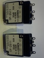
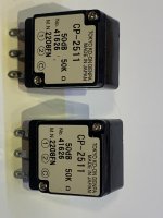
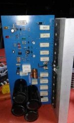
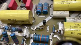
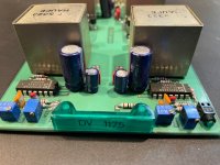
I knew some of the parts he used were not what I would choose today, so the cement block 1R and 0R47 resistors will be replaced by 5W metal films. The 220uF caps of unknown brand will also be replaced, but I am not sure yet what to use. I have 220uF Silmic IIs (25V and 35V) and Nichion Muse FG (25V) in my drawer and some Nichion Muse KZ (50V) and Nichion Muse ES bipolar (50V) on order. Any suggestions which to put where would be appreciated.

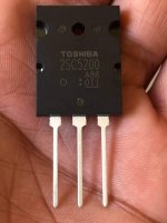
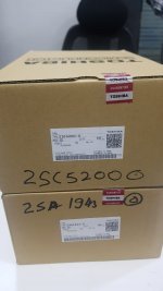
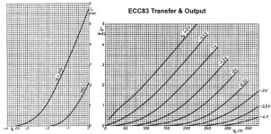
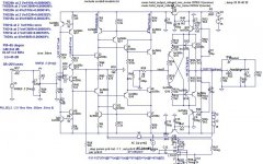
I also noted that in an old thread, the ZVP3310A was mentioned as a good replacement for the 9610s. http://www.diyaudio.com/forums/pass-labs/172987-zvp3310-good-choice-input-fet-aleph-30-a.html
It as an old thread, so I would be interested to hear if other people have since tried this and what their results were. I know they are not in stock at Mouser, Digikey or Farnell/Element14 but I think I bought about 25 ZVP3310A many years ago, so could hope to get a few matched pairs (if I can find them haha).

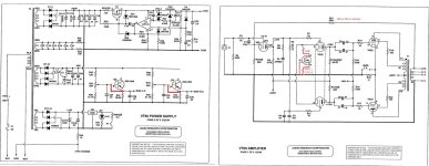
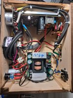
The power supply currently consists of:
  • Talema TRT1000240 1kVA 230V primary 2 x 40V 12.5A secondaries
  • Standard GBC type bridge rectifiers
  • CLC :
    • 47000uF/63V F&T GM
    • Intertechnik aircoil 2.2mH 0R46 (1.4mm copper)
    • 47000uF/63V F&T GM

The first problem I noted was of course that in this configuration, the rails will be much higher than spec (according to psu designer about 51V with an 11mV ripple). As the mains voltage where I currently live is 240V, I can expect another 2V, giving me rails of just over 53V. I understand from the service manual that the circuit will adjust bias automatically, resulting in a lower bias, so I expect dissipation to remain 300W per monoblock.
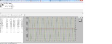
What alarmed me is that according to psu designer, the ripple the first 47000uF cap will see is double the rating of the cap (max. 13.2A according to datasheet). Not good.
The amp has not seen that many hours (I have too many amplifiers 😎) but the first cap could be seriously aged by this maltreatment. How can I check the condition of the cap? If it is still OK, I assume swapping the hard driven first cap with the hardly stressed second one will prolong life?

Obviously, the ripple the first cap sees has to be significantly reduced. Ideally the rail voltage should be lowered as well (the circuit will automatically increase the bias to accomodate for this). Just adding capacitance does not seem the best solution.

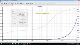
I remembered something EUVL said about adding resistance in the psu (when I tried to get rid of hum in my Aleph H). I played around with psu designer and came up with the following simple solution: Convert the CLC design into RCLC by adding 0R75 resistance before the first cap. (N.B. I also tried LCRC using the same values, but psu designer showed excessive voltages experienced by the bridge rectifier and a higher ripple at the load).

According to psu designer, with the RCLC psu the first cap ripple is less than 50% what it was previously (now within datasheet spec) and the rail voltage drops to 45V (from 51V). The resultant load ripple (simulated as 17R in CLC and 13R is RCLC to give about 150W dissipation per rail, to compensate for the circuit automatically adjusting the bias to keep dissipation constant) hardly changes (I surmise it is probably more dependent on the size of L and C2).

I assume this solution will add quite a bit of heat (psu designer calculates 6A RMS at 4V5 RMS through the 0R75 resistor, so about 54W per mono block). I will have to add fans for these Aleph 2s anyway, and especiially to survive the extra heat. I have some old PC fans of various sizes but am unsure if placement in the enclosure will give enough relief. Has anyone tried this?

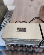
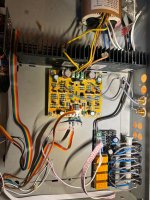
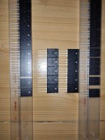
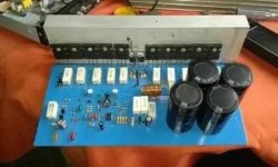
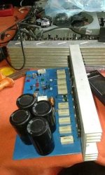
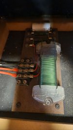
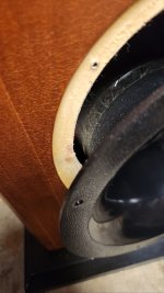
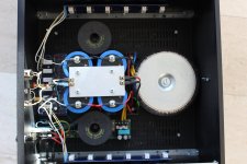
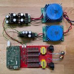
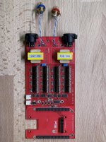
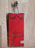
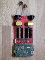
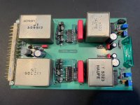
Having had plenty of trouble with radiated noise recently while testing a newly built pumpkin in my shed, I am wondering if the placement of the coils in my amps could be improved upon. Ideally I would move the transformer and coils to another box (perhaps even try a regulated psu) but a 4 box stereo amplifer really is a bit too much. I have attached a photo of the current layout (don't take any notice of the old soft start to the right of the bottom coil; it has since been replaced by an NTC).

Will a steel cover over the transformer (if I can find one that big) and/or coils (assuming I have enough room to do this) make a big difference?
Any suggestions are welcome!

Attachments

  • current aleph2 psu at 150W.jpg
    current aleph2 psu at 150W.jpg
    199 KB · Views: 346
  • proposed RCLC aleph2 psu at 150W.jpg
    proposed RCLC aleph2 psu at 150W.jpg
    197.6 KB · Views: 342
  • top view.JPG
    top view.JPG
    308.8 KB · Views: 357

Which bass for 3" midrange dome tweeter?

Hallo,
I have already shown my combination of ribbon and HiVi 7500 in the midrange dome thread, but I am not satisfied with the cheap 10” bass, I am thinking about how I should design the bass section.

The HiVi 7500 will later be separated passive at 500-800 Hz with 12 Db.

I am considering one 8“ or two 6" drivers.
The loudspeaker should later also work directly on the wall.
That's the plan...
A closed volume with a high-pass filter (condenser 900-1700uF).
If the bass tends to boom when placed on the wall, the high-pass filter can be bypassed.


Simulation 8" SB23NRXS45-8 with and without high-pass filter.
SB23NRXS45 geschlossen.JPG


Simulation 2x6" SB17NBAC35-8
SB17NBAC35-8.JPG

Without bass reflex the maximum volume is limited but would be enough for me.
I like the slight drop in the bass range, which helps to avoid booming.


My questions:
Are two parallel 6” speakers too loud for the HiVi 7500?
What do you think about the arrangement of two 6" bass drivers above and below the tweeter-midrange unit (distance center to center 400mm)?

Unbenannt1.JPG

If you still have questions or suggestions, please!

Attachments

  • Prototyp1.jpg
    Prototyp1.jpg
    70.3 KB · Views: 56
  • Like
Reactions: motokok

Buzz generated by the PSU

Hello everyone.
I'm working on my first class DYI hifi amp.
A "simple" assembly of pre-assembled boards ...let's say a school prototype with no pretensions other than to sound decent. The result isn't top, but I learned many lessons that I hope to apply at best way in V2.
However, there is a very annoying problem for which I would like the valuable opinion: the PSU, I know it is not the best, has two 12v auxiliary outputs. I needed one to power the LEDs on the front panel. Well, if I connect even a single LED to one of the outputs, a constant buzz is generated regardless of the volume setting. With the 12v contacts empty, nothing. I also noticed that if I touch one of the two contacts (under load) with a multimeter tip, the buzz fades out by half or so. The case is made out of wood with no grounding.
Can you help me remove the problem?

Attachments

  • 20250107_163315.jpg
    20250107_163315.jpg
    392 KB · Views: 63
  • 20250103_173002.jpg
    20250103_173002.jpg
    627 KB · Views: 55

WTB Empty stand mount cabinets for Fostex FE206E

As per title, standmount cabinets for fostex 206e
Must be extremely well made, unfinished is fine as I can do that.
Or suggestions on where I could find some.
I might be able to build some, so plans also useful.
I do have the original kirishima cabinets for them that I would happily swap, but you would have to come to me, as my car isn't big enough, they are huge and heavy!
Cheers
Graham.

Attachments

  • 20250103_095156.jpg
    20250103_095156.jpg
    304.9 KB · Views: 45
  • 20250103_095206.jpg
    20250103_095206.jpg
    328.9 KB · Views: 44
  • 20250103_095134.jpg
    20250103_095134.jpg
    370.9 KB · Views: 42
  • 20250103_095116.jpg
    20250103_095116.jpg
    344.4 KB · Views: 42

"Immunising" the following design

I'm designing a combination HPF + boost/soft clipper for use with bass and electric guitar.

This is the general schematic:

1736331158263.png


Since I'll build straight to SMD, I want to minimise the chances of having issues with noise and/or oscillation.
U1/U2 will be an OPA1678, while U6/U8 (don't pay attention to the references) would be an NJM5532. They will both feature 0.1u MLCC caps to ground at the V+ pin, of course.
Power supply will be 9->24V.

The main points of contention are:
  • would it make sense to add in a resistor (like, 1kohm) in the feedback path of the buffers (U1/U8)? I've read that sometimes this makes the design more resilient.
  • what about input resistors or input capacitance?
  • I'm assuming that with the aforementioned opamps, there wouldn't be any issues with phase reversal, right? Were I to use different opamps (say, a 4580 or a 4558, or a TL072) is there a way to ensure that phase reversal would never happen? I remember reading that adding a 3.9k resistor at the positive input of a non-inverting opamp sort of cures the problem.
  • are there any areas that could do with some optimisation, or things I may have overlooked?

Thanks.

For Sale NOS AmpOhm Capacitors

I am selling my (private) stash of AmpOhm capacitors. These were bought in 2010 and never used. They are not made anymore.

  • 4 Pcs. PF-XAL-AL, Paper in Oil Aluminium Foil, 10uF 300VDC, €60,-- each
  • 4 Pcs. PF-XAL-AL, Paper in Oil Aluminium Foil, 5,0uF 300VDC, €40,-- each
  • 6 Pcs. FE-XAL-AL, Polyester Film Aluminium Foil, 6,8uF 630VDC, €60,-- each
  • 2 Pcs. FE-XAL-AL, Polyester Film Aluminium Foil, 2,2uF 630VDC, €45,-- each

Small discount possible when buying all in one go.

Shipping costs available on request. I am located in the Netherlands.

AmpOhm.jpg

F5m kit problem?

Had a perfectly working f5m playing music then just stooped .blowing ac fuses, Found it was
left channell issue,.
Removed mosfets and jfets , found mosfets faulty , jfets tested as fine.
So replaced mosfets re installed the jefets new r6 and r7.
connected power and was slowly ajusting bias, going well then all of a sudden
smoke started coming from R5 which is the 22w 2watt resister included in the kit,
should i just replace R5 or do i have a problem with the jfets ,
thanks
Glenn Kaspar

DIY DAC and 12V trigger out - Avoiding noise

Hi all.

I am in the process of designing a new 8 channel DAC/active XO/preamp for my active 4-way system and I want to add a 12V trigger out to remotely start the amplifiers, four Fosi Audio ZA3.

The DAC will have a 5V SMPS to power the standby/activeXO/MCU circuit (Raspberry Pi based) and a linear PSU that provides 5V for the DAC digital circuit and +12V/-12V for the output stage (a simple opamp based I/V circuit).

My concern here is how to provide 12V to the trigger out circuit, in special how to avoid introducing noise and how to avoid ground loops. My previous experiences with Fosi's trigger in was terrible. The port doesn't seem to be isolated from the main circuit so, if you connect a noisy device, the noise goes directly to the audio.

In my current design, I used the 12V line from the linear PSU (the same that powers the I/V stage) through optocouplers to ensure the complete isolation between the MCU circuit and te 12V circuit. My concern here is to introduce noise in the I/V stage, coming back from Fosi's trigger circuit.

Another option that I see would be to add a new tiny 12V PSU just for this circuit (a linear or a filtered SMPS as Fosi's trigger in will introduce noise into the system).

For the experienced electronic circuit designers here, would you please recommend the best approach? Maybe adding filter caps in the trigger circuit?

Tube amp with 6N13S and 50Ohms Headphones schematic?

Dear Folks,

Looong time ago I developed some DI boxes and Guitar preamp stages with tubes. Mostly using nice russian NOS tubes, or brand new type from JJ.
Well, it´s winter and I need a new project beside fom hacking C-code and some "sand"-processors.
In my stock there are two nice 6N13S tubes, waiting to be used. 🙂
Any hints for a prooved schematic using this fine tubes to drive a standard 50Ohm Headphone ( Sennheiser HD558 )??

Best Regards
Karsten
Edit: Forgot that C in Cyrillic is an S 🙂

repurpose a hypex SMPS400N400 for a 3E AUDIO 260-2-29A PFFB Stereo amplifier?

I have a broken Hypex NC400 with a SMPS600N400 power supply (that is fine). The output of the supply is 2x 65V, too high for the 3e audio amp board (3E AUDIO 260-2-29A PFFB Stereo amplifier). Is it possible to step down the voltage of the SMPS600N400 to say 48V while maintaining the max 650 watt? Or is this not a good idea anyway and can I better buy also a new power supply that is already 48V (like the micro audio SPMP-R2)?

GainWire Mk3 CFA pre/phone amp with very low distortion

I showed some time ago GainWire mk4 balanced preamp, but there was no interest for balanced preamp, as it seems.

Now here is GainWire mk3 CFA preamp with very, very low distortion at all frequencies and output levels.
It could be used as level preamp or headphones preamp for low or high impedance headphones.

The gain was set to 12 dB (3.6 times).

If used as a line preamp distortions are as below:
THD1k at all practical levels is zero in simulation.
THD20k is below 1ppm at all practical levels, 0.14 ppm at 4Vef at the output.

If used with high impedance headphones distortion is very similar to the line preamp mode.

If used with low impedance headphones as Grado 32 ohm then distortion is as below:
THD1k is 1.05 ppm at 2Vef on the output.
THD20k is less then 4 ppm at 2Vef.
Grado headphones will give SPL of 99.8 dB at 1mW and that is 0.18Vef, 2Vef will produce 0.125W, more then enough.

I designed two types of PCB, for single channel with no power supply and for two channel with power supply(similar as GainWire mk2.
Damir

Link to the post what transistors should be matched.
https://www.diyaudio.com/community/...ery-low-distortion.296545/page-4#post-4844159

Link to the BOM.
GainWire mk3 CFA pre/phone amp with very low distortion - Page 7 - diyAudio

Matching.
https://www.diyaudio.com/community/...ery-low-distortion.296545/page-4#post-4848920

Thermal bonding of the BJTs, examle.
https://www.diyaudio.com/community/...ery-low-distortion.296545/page-5#post-4854722

For capacitance multipliers (Q27, Q28) better use BC337-40/327-40, less prone to quasi saturation.

Updates, some values changed.
http://www.diyaudio.com/forums/soli...e-amp-very-low-distortion-12.html#post4861045

PCB error and how to rectified it :
silkscreen error:http://www.diyaudio.com/forums/soli...-phone-amp-low-distortion-12.html#post4861045
http://www.diyaudio.com/forums/soli...e-amp-very-low-distortion-20.html#post4912003

Modification to get better clipping behavior: http://www.diyaudio.com/forums/soli...-phone-amp-low-distortion-28.html#post5158715

How to correct layout error on the board layout ver. 1.3. Ther is one short connection. http://www.diyaudio.com/forums/solid-state/296545-gainwire-mk3-cfa-pre-phone-amp-low-distortion-
29.html#post5212455

BOM for PCB version 1.5
https://www.diyaudio.com/community/...ry-low-distortion.296545/page-20#post-7137481

Attachments

  • GainWire-mk3-GNFB-CFA-sch.jpg
    GainWire-mk3-GNFB-CFA-sch.jpg
    196.4 KB · Views: 9,785
  • GainWire-mk3-GNFB-CFA-LG.jpg
    GainWire-mk3-GNFB-CFA-LG.jpg
    253.8 KB · Views: 6,022
  • GainWire-mk3-GNFB-CFA-CLG.jpg
    GainWire-mk3-GNFB-CFA-CLG.jpg
    233.4 KB · Views: 4,391
  • GainWire-mk3-GNFB-CFA-PSRR.jpg
    GainWire-mk3-GNFB-CFA-PSRR.jpg
    135.5 KB · Views: 4,149
  • GainWire-mk3-GNFB-CFA-output_impedance.jpg
    GainWire-mk3-GNFB-CFA-output_impedance.jpg
    192.2 KB · Views: 5,301

Hello from Finland

I'm 48 years old steel factory worker from Finland. I always prefer to do things by my own hands, when I can reason it somehow (usually getting better or better suiting or unique product for the same price, or preferably even save some money). I have pretty modest set of tools and I don't understand electronics, but I get things done. I don't like to use too much time for thinking and hesitation, I just need get to work. With that said, I'm here because I would love to build my own Genelec 8020 "killers", but as cheaply as possible (for home theatre and music), and perhaps with a subwoofer. My wife loves how those white speakers look.

And then I would also love to have something between 8010-8020 as my "home studio" computer speakers.

Future of vintage audio equipment

Hi, sitting here thinking about what will happen to vintage audio equipment in the future, let's say 20 years from now? The reason for these thoughts is that I now have a complete system that I want to take with me far into the future, but what about parts in the future? Electrolytic capacitors, v.t. Displays, transistors, laser pickups, etc.. those of you who think the same, how do you future-proof your audio equipment? I'm thinking that having a similar set standing as a backup could be a solution, but need some tips and advice..

SE to Balanced cable wiring question

Hello,

I have RCA SE signal and need to send it to balanced input with TRS.
( never used balanced devices .... and need to keep the smoke in 🙂 with your help ... )

After some schematic / wiring search found attached wiring - I hope it is correct ?
( RCA RED --> TRS RED - it is OK for me - it is logical 🙂 ..... no questions here .... )

BUT why ? ...
1. RCA ground ( black ) is connected to TRS black ( negative ) and not connected to TRS Shield ? What is the 'logic' or explanation of this ?

Please, explain to me why we use Positive and Negative pins on TRS to send the signal into device ?

Thank you for your time and help,

Emil

Attachments

  • Q1.jpg
    Q1.jpg
    82.6 KB · Views: 93

DIY tape recorder

Hello guys! I have an idea to build my own tape recorder (for home). I will use tape from cassettes only with a playback head for two channels (stereo). The output from the tape recorder is only for headphones (or for speakers). I need to find circuits for an amplifier (to get a relatively clean sound/color the sound and amplify it for comfortable listening) and good motors for pulling the tape. I am ready to consider ready-made solutions for this (in terms of ordering from Aliexpress and simply connecting them together inside the device).The tape pulling diagram is attached. Thanks.

PureDSD DAC DSC2 With BeagleBone Green Board

Almost the best Pure DSD R2R DAC with no DAC chip just digital/analog filter, open sourced by puredsd.ru to go with hqplayer.
  • Network based streamer, with NAA (Network Audio Adapter) embedded for hqplayer front end.
  • HQPlayer preferred to upsample PCM/DSD to DSD256/512.
  • DSD signal received by BBB single board computer is further isolated then reclocked.
  • Transformer based output, outperforms Lundahl LL1684.
  • NOS NXP 74AHCT595D (not newer NXP with X logo) as recommended by designer for best sound.
  • 128 Tantalum Nitride Precision Thin Film Chip Resistors ($1 each) deployed on resistor boards.
  • MSR860 Soft Recovery Rectifiers and low noise LT1963 regulators for off board first stage power supplies.
  • Dual stages ultra low noise regulators for digital processing.


DSC2 DSD R2R DAC with hqplayer NAA embedded (BeagleBone Green running botic firmware).
Single end or balanced output with toggle switch at the back of PCB.
Three separate low-noise power suppliers built with Toroidal transformers, MSR860 rectifiers, Panasonic-FC capacitors and LT1963 regulators.
The BeagleBone board position can also accept Amanero combo384 or combo768 card.
Only DSD (DSD512 native mode preferred) encoded stream from hqplayer is accepted.

Asking USD 450 or AUD 695

Please complete payment within 3 business days via Paypal or bank transfer, I will ship this unit within 3 business days after the payment cleared.
Buyer pays for postage.
Or cash on pickup in Bulleen 3105 Australia.

Attachments

  • 20241112230339.jpg
    20241112230339.jpg
    1.1 MB · Views: 170
  • 20241112230118.jpg
    20241112230118.jpg
    531.9 KB · Views: 162
  • 20241112230209.jpg
    20241112230209.jpg
    558.6 KB · Views: 150
  • 20241112230225.jpg
    20241112230225.jpg
    758.5 KB · Views: 148
  • 20241112230238.jpg
    20241112230238.jpg
    697.9 KB · Views: 155
  • 20241112230322.jpg
    20241112230322.jpg
    800.6 KB · Views: 155

Behringer Xenyx Q502 USB - driver problems

Any idea why there are cracklings (echo like) when I use the mix console as external audio interface?
It worked once, then I tried to use usb piano keyboard and messed the driver and settings (to lower the latency)
Then I switched to the onboard audio and actually forgot about the problem..

Now I am trying to use the console like audio interface (just for listening online music) and cannot set it back.
Cant find specific behringer driver, the problem is both if I use 44.1 and 48k rate.

BPPBP - Bruno Putzey's Purist Balanced Preamp (well a balanced volume control really)

I'm currently doing some research on preamp concepts which basically resemble a balanced volume controller, if I may say so.

While doing so, I came across a design by Bruno Putzey which he lays out here: http://www.hypex.nl/docs/papers/The G Word.pdf (originally written for Linear Audio Linear Audio | your tech audio resource , Volume 5 came out in April 2013 with a free PCB for it)

This design includes the following features:
- Buffer as input stage with input biasing network
- Difference amplifier between input stage and variable gain stage, with the output of the difference amplifier being referenced to the cold point of the volume controller
- Linear potentiometer used as feedback element in an inverting amplifier, not as attenuator
- No output stage (almost)
- DC removal circuit (2nd order low-pass filter whose output is subsequently subtracted from the signal)

So basically bal to unbal, followed by unbal active volume control as part of a difference stage, then back to bal with passive balanced impedance output.

Has anyone actually built this preamp? If so, what are your experiences with it? And what do you think of the concept and design as such?


(EDIT: Just saw from AndrewT's post here that the EDN version of the article published here has some very valuable additional comments.)

For Sale Studio summing amp, line amp BFE DV1175

Hi folks,

here for sale a summing amp also to use as line amp with two channels. Signal up to +22dBu. Balanced groundfree in/out with high quality studio transformers.
Can be used as summing amp in a mixer with an input rail or line amp with up to 20dB gain. For example also for long signal distances of up to 900ft / 300m for FOH use.
Incl. schematic and pinout.
Asked price is 75,- $ + shipping. Serveral available......(The cost of one transformer btw is about 110,- $), questions are welcome.....

regards

HP

Attachments

  • 250103-V1175-back.JPEG
    250103-V1175-back.JPEG
    536.4 KB · Views: 77
  • 250103-V1175-front.JPEG
    250103-V1175-front.JPEG
    527 KB · Views: 64
  • 250103-V1175-top.JPEG
    250103-V1175-top.JPEG
    587.6 KB · Views: 75

Onkyo DX7210 CD player..gear problem

Hello...im not much of a stereo fixer but can fix almost anything else.
i hook up this used onkyo dx-7210 cd player and get this gear slipping sound so take it apart and find it is in fact two gears not meshing. I find this youtube video and this guy has the EXACT same gear problem. The issue is i cannot tell how he fixed the gears because its not in english. I tried for hrs. to translate the video to english with no luck. Im hoping somone on here can tell from the video what this man did to fix the gear problem. I can visually tell that the gears are not tight together when it cycles. Your help in this matter would be greatly appreciated. thank you
YouTube

G'day from Australia

Hi to all members. I am Kevin a retiree and a new member from Australia. I am interested in home theatre and 2 channel music. I have no technical skills but am fortunate that my son is a Electronics Engineer and designs, builds and repairs amplifiers as a hobby. He has the skills but has no time. I am hoping to find some projects to build and will coopt my son for the construction.

Justice for KEF Q100

Kef Q100... yes i know that one. Do you really know that speaker?
Do you know that feeling when you see something, something that gets under your skin. Gently crawl under the skull and torture brain at night when you lie down, then gently whisper that driver it's the chosen one.

This is exactly how I felt when I saw the construction and engineering that was put into this driver. But the comments and various reviews indicated that it was just an ok speaker, and those things turned me off from buying it.

But wait someone opened the box and the crossover was only with three components.

One coil on midbass on tweeter capacitor and resistor.

Ok, I smell a rat.

This means war, Kef.

I prayed to the gods of DIY, and went to war against poorly executed Crossovers.

Made new enclosures, new measurements in new enclosures and these are the results.
Mic is Umik-1

SKRETNICA.png

Crossover

0.jpg

On axis

output_ket7vU.gif

Of axis 0-10-20-30-40-50

3db-oct.png

3db/oct

I don't know exactly how the speaker behaves below 200hz due to the measurement in the room. This response is combined from two measurements, read approximation…

6db-oct.png

6db/oct
  • Like
Reactions: maty tinman

For Sale Passworks bi-amp 6-24db crossover board

Having a clear out: I have a Passworks 6-24db active crossover PCB. As can be seen some the caps and trim pots have been installed. At the time I was unable to get the transistors from the DIYaudo, they are available now.

This crossover can be configured in many slopes and crossover points. There is a build guide section over on DIYaudio covering the build implementation.

53660373920_e3e3be1cb9_h_d.jpg


£50 + shipping

Wondom/Sure BDM8 TPA3255

Hey guys I just received a wondom bdm8 amplifier I ordered from their store on AliExpress. Just like all the Chinese boards there is little to no documentation on them so I was wondering if anyone here has one and if they can share their experiences with it? My initial impressions are that it sounds very good and seems to have plenty of power using an adjustable SMPS at 36v 10a but can go to 50v. I haven't tried anything over 36v yet but I will. Theres alot of connections on the board that aren't explained at all and was hoping that I can figure out what they are.

Ian asynchronous I2S and S/PDIF FIFO KIT group buy

2023-12-18 Ian GB2023 in Now OPEN

Hi Guys,

Ian GB2023 is finally started after a long time of preparing. I thank you for your patience.
It took me pretty long time because there are lot of new and updated products in 2023.

To make your life easier, this time, I’ll list all items at https://iancanada.ca. You will have a total 12% discount for this GB because of the Paypal fee is also eliminated using credit card payment.

I separated products in different catalogs, and put many solutions and configurations in the Project sector. I believe that will be a great help to select products for your project rather than a long list. You will find more surprise if you put the projects into your shopping cart.

You will receive a diyAudio message with the check out instructions and the discount coupon code.
Please do let me know if you don't receive the message in two days.

Terms and conditions:

One year warranty for all finished PCB assembly. That means repairing service is free within 1 year from date of purchase.
If the damage is caused by your DIY activities, please kindly donate some money to my PayPal account to cover my labor of service. Fixing a board usually takes me 1 hour (troubleshooting, rework the SMT, test and repackage). Buyers need to pay round-trip shipping and parts in either case.
I cannot 100% guarantee a fix if it is badly damaged, for example, by short circuit or other critical failure.
I will also provide firmware upgrades service for free within 1 year from purchases; Buyers also need to pay shipping.
Please also kindly understand that I’m not responsible for debugging the user's DIY system, I only guarantee my products are functional. If you have any problem with your system, please post the issue on the thread, other community members and I will try our best to support.
All GB items are for DIY uses. All sales are final and no return and refund will be accepted.

Some useful links

Webstore: https://iancanada.ca
Documents: github.com/iancanada/DocumentDownload

New Updates: https://twitter.com/iancanadaTT

Streamer solutions: https://www.diyaudio.com/community/...fight-the-jitter.192465/page-414#post-7263122

DAC solution: https://www.diyaudio.com/community/...fight-the-jitter.192465/page-504#post-7478491


2023-12-07
GB2023 will be stated very soon. Thank you for your patience.

2023-06-11 9:43pm
Ian GB2023 for SC-Pure, FifoPiQ7, UcPure MkIII and so on

*Note1:
If you want to join this GB2023, Please just put your ID and items to the interesting list at the end of this thread so that I can reserve the GB products for you. Of course you have no problem to cancel your items if you change your mind later because it’s just an interesting list.

*Note2: This post will be kept continuously updated for new information, so please come back often to check.

Normally I run a group buy (GB) every two years. 2023 is a very special year. COVID is gone, and I have a lot of great products released/upgraded or to be released. So, I think it's time to prepare for the new possible GB2023.

As usual,to express my thanks to diyAudio community members for their long time support, I’ll offer a one time 10% discount during the GB2023 run time window.

Some items are already released and available, you can buy them now by sending me the order form back to me if you don’t want to wait for the GB2023 discount.
All items will be listed here: https://github.com/iancanada/DocumentDownload

Thanks again.
Ian

GB2023 by Ian


Here are the GB2023 new products (partly):

. SC-PURE 22.5792 / 24.5760 / 45.1584 / 49.1520 MHz
. RFX OCXO 45.1584 / 49.1520 MHz, Adapter KIT, SquarePi KIT
. FifoPiQ7
. FifoPiMa
. TransportPi AES
. HdmiPi Pro
. TransportPi Digi
. UcPureMkIII
. UCbalancer KIT
. LinearPi MkII
. PurePi
. UcPi
. UcConditioner MKII 5V and 3.3V
. MonitorPi
and MonitorPiPro
. ES9038Q2M DAC MkII
. OPA861 I/V
. StationPi SMT
. StationPi Pro
. ShieldPi Pro/MKII
. GPIO extender

Free
stuffs (partly):
. StationPi PCB (limited stock)
......


Other old products can also be found here: https://github.com/iancanada/DocumentDownload
My twitter: https://twitter.com/iancanadaTT

Streamer solution
https://www.diyaudio.com/community/...fight-the-jitter.192465/page-414#post-7263122


SC-PURE0 by Ian, on Flickr


FifoPiQ7_0 by Ian, on Flickr


UcPureMkIII by Ian, on Flickr


TransportPiAES by Ian, on Flickr


HdmiPiPro by Ian, on Flickr


PhaseNoiseComparison by Ian, on Flickr


OCXO_RFX_Audio by Ian, on Flickr


UcBalancer0 by Ian, on Flickr


LinearPiMkIIDual by Ian, on Flickr


OPA861_1 by Ian, on Flickr


GPIOextender1 by Ian, on Flickr


MonitorPiPro0 by Ian, on Flickr

ES9038Q2MDMII by Ian

ReceiverPiDDC by Ian

DAC solutions
Login to view embedded media Login to view embedded media

Attachments

Projects by fanatics, for fanatics
Get answers and advice for everyone wanting to learn the art of audio.
Join the Community
507,759
Members
7,887,240
Messages

Filter

Forum Statistics

Threads
406,173
Messages
7,887,240
Members
507,759
Latest member
Lotusfan