Hi msamkl
I asked Greg about your posts and he suggested the following:
hope this helps

I asked Greg about your posts and he suggested the following:
There is no one best way but it's good practice to have a star earth point for all signal wiring and a mains to chassis ground connection for safety. Then connect the two either through a resistor of 1W and 1-10 ohms paralleled with back to back 1A diodes OR a direct link to mains ground.
Sometimes no connection between the two gives the best result but can be a problem with floating and connection to other equipment.
Sometimes connecting other equipment with a different grounding arrangement can cause the problem and it's down to finding the best compatible arrangement for your combo.
hope this helps
Hi KLe...
I've already contacted Greg many times but we were unable to solve the problem. You know that is very difficult to describe such problems to someone through emails or forums. I'm sure that if Greg were here beside me, he could easily find what causes the noise and he would eliminate it. The noise exists even if there is nothing connected to the amplifier but only the speakers. When I disconnect the mains power ground from the chassis, the noise disappears. If I only connect the mains power ground to the chassis and nothing else on to it, the noise becomes quite inaudible(I have to get my ear very close to the speaker to hear it)
KLe said:Hi msamkl
I asked Greg about your posts and he suggested the following:
hope this helps
I've already contacted Greg many times but we were unable to solve the problem. You know that is very difficult to describe such problems to someone through emails or forums. I'm sure that if Greg were here beside me, he could easily find what causes the noise and he would eliminate it. The noise exists even if there is nothing connected to the amplifier but only the speakers. When I disconnect the mains power ground from the chassis, the noise disappears. If I only connect the mains power ground to the chassis and nothing else on to it, the noise becomes quite inaudible(I have to get my ear very close to the speaker to hear it)
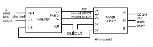
Upupa Epops said:Terry, this grounding is wrong : you must not lead input ground by common wire with output ground into PS, but by two separated wires. You must imagine, that output ground have not " zero " resistance and by continuous current from load is " modulated " input ground = positive feedback = instability.
This is not wrong.
Look carefully at the diag. The currents in the speaker / OP stage
loop will not modulate the IP ground at all.
And the currents in the transformer / power supply loop will
not modulate either the IP or speaker ground either.
I have drawn a dotted line where the amps gnds connect, but Greg
has done a ground plane on the pcb so this will be very low impedance.
Perhaps you can post a diag of your idea?
Cheers,
Terry
Terry Demol said:
This is not wrong.
Look carefully at the diag. The currents in the speaker / OP stage
loop will not modulate the IP ground at all.
And the currents in the transformer / power supply loop will
not modulate either the IP or speaker ground either.
I have drawn a dotted line where the amps gnds connect, but Greg
has done a ground plane on the pcb so this will be very low impedance.
Perhaps you can post a diag of your idea?
Cheers,
Terry
Terry, have you also constructed the GB150? If so, did you apply this grounding schema that you suggest? You have connected the input jacks earths to the chassis ground. What circuit did you put between them? Is it the same that Greg suggests (1 resistor 2,7 ohm and two anti-parallel diodes) or just a resistor?
Thanasis.
AndrewT said:Hi,
I have only two comments on the latest schematic/layout.
The star ground on board the PCB relies on the amp designer getting it right.
Maybe connect the mains earth via a resistor to Star ground in lieu of the twin resistors to input RCA grounds.
All else looks workable.
Where the two resistors connect the circuit ground is probably
not so important because their purpose is to lift a potential loop.
However there will still be a current loop with the resistors and
it's path will be through the mains ground, into the pre amp and
back through the interconnects shield (common). So I picked
the IP socket as the closest point to the interconnects ground.
WRT your post below, no I havent built the SKA, but just based
my reply on logic and what worked in the past.
Certainly on both of your previous diags there are current loops
that are shared.
Cheers,
Terry
Upupa Epops said:Terry, read closely : input and output ground must not be common, must lead to supply by two wires. If Greg have load grounded at PA's PCB, so it is uncorrect.
The IP ground and OP ground -have- to be joined at some
point. Are you saying they both join at the power supply common?
From what you have described, I can only see interactive current
loops as a result.
Can ou should do a sketch for all of us to see if you are to challenge
what has been done so we can clearly understand your thoughts.
Cheers,
Terry
tinitus said:msamkl
I dont think you should connect input ground on ampboard to supply ground - it has its own ground plane on ampboard - you risk making a ground loop
And maybe you get less noise if you connect supply ground/earth after electrolytes
Maybe you are right about it but if you take a closer look to the schema attached you will see that Greg advise us to do so...
I've just followed this schema.
Attachments

pinkmouse said:
From a safety point of view, you should never have anything but a direct connection between power ground and chassis. Put anything you want in the signal ground path, but leave the safety ground well alone.
Thanks, Pinkmouse. I won't...
Hi,
Pinkmouse,
I agree, always connect mains safety ground (mains earth) to chassis and NEVER disconnect it. Absolutely NEVER.
But power ground refers to PSU. This is different. It is safe to use resistors between power ground and safety ground. and also safe to use resistors between signal (clean) ground and power ground.
By keeping the three grounds (power, signal, safety) separate, you can and may need to experiment with various interconnections to achieve silence.
I wish Terry and Jacco could reach a conclusion, as I'm sure the result would be nirvana.
In closing, I would never connect signal ground to safety ground directly.
")
Guys,
Three earths.
Signal earth, which handles input gnd, fb gnd and input bias gnd.
Power earth, which handles power supply gnd, speaker cold.
Safety earth, which handles IEC earth to chassis.
Signal earth should be connected to power earth via a 10R resistor and back to back 3A diodes.
Power earth can be left floating, OR also connected to safety earth via a 10R and back to back 3A diodes.
Safety earth MUST ALWAYS BE CONNECTED TO CHASSIS, EXACTLY AS PREVIOUSLY MENTIONED. FAILURE TO CONNECT CHASSIS TO EARTH IS USUALLY ILLEGAL AS WELL AS DANGEROUS.
Sometimes, depending on the earth regime of the source, it is better to float power earth. Medical equipment does this, particularly on EEGs and ECGs since the tiny currents involved can be seriously compromised by a noisy earth. Noisy earth is common in a hospital environment, of course.
Cheers,
Hugh
AKSA said:Guys,
Three earths.
Signal earth, which handles input gnd, fb gnd and input bias gnd.
Power earth, which handles power supply gnd, speaker cold.
Safety earth, which handles IEC earth to chassis.
Signal earth should be connected to power earth via a 10R resistor and back to back 3A diodes.
Power earth can be left floating, OR also connected to safety earth via a 10R and back to back 3A diodes.
Safety earth MUST ALWAYS BE CONNECTED TO CHASSIS, EXACTLY AS PREVIOUSLY MENTIONED. FAILURE TO CONNECT CHASSIS TO EARTH IS USUALLY ILLEGAL AS WELL AS DANGEROUS.
Sometimes, depending on the earth regime of the source, it is better to float power earth. Medical equipment does this, particularly on EEGs and ECGs since the tiny currents involved can be seriously compromised by a noisy earth. Noisy earth is common in a hospital environment, of course.
Cheers,
Hugh
Hugh,
What happens when sig earth, or, IP gnd point is already
connected to power earth as -appears- to be the case with
SKA amp.
Your scheme, which is essentially the same as what Pavel has
suggested to me, can not be implemented without altering the pcb
and adding a 10R to isolate the gnds as AKSA and DPA have.
Can anyone give any further info WRT the grounding on
SKA PCB?
Cheers,
Terry
Hi all,
I completely agree with AKSA.
I wish I could summarise as well as he.
Edit,
the ground lift referred in some commercial gear must be the optional floating power ground that AKSA calls up.
A few interpret ground lift as separating chassis from safety ground with potentially lethal results.
How can we as a forum advise a safe method for correcting wrongly connected equipment?
Is there a permanent location that could store and easily retrieve this advice?
IMO I think Upupa is right, we should not forget that we mostly use to build 2 ch amplifiers meaning diffrent ground currents >> crosstalk.
The typical "10 R" is a compromise telling there's ground current issues not properly adressed.
A bit different storry would it be if we have galvanically isolated PSU's for each channel.
Cheers Michael
The typical "10 R" is a compromise telling there's ground current issues not properly adressed.
A bit different storry would it be if we have galvanically isolated PSU's for each channel.
Cheers Michael
- Status
- This old topic is closed. If you want to reopen this topic, contact a moderator using the "Report Post" button.
- Home
- Amplifiers
- Solid State
- Simple Killer Amp Constructor Thread