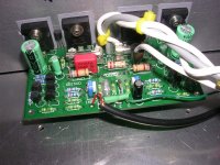
construction detail
Macka,
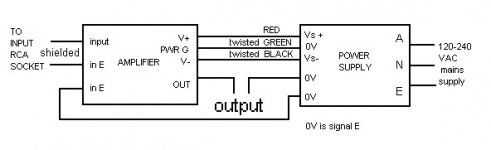
Great idea! As I build I will also try and post some key step pics. Looks like the detail in this constructors section is from a different amp - the input wires look like different colours. I was wondering what the green sleeve-like component was at the input? I'm starting to do some comparisons between the other pics you've posted (http://www.diyaudio.com/forums/showthread.php?s=&threadid=72172&perpage=10&pagenumber=9) with the ones here and also at http://www.diyaudio.com/forums/showthread.php?s=&threadid=72172&perpage=10&pagenumber=23 and trying to relate these to the instructions Greg sent. I guess the only items that remain obscure is to see the photo's of point to point wiring between transformer, PS, amplifier boards and the RCA inputs and binding post outputs. I realize this is pretty general at this point but when the kit gets here I should have more specific questions - so far as I do the thought experriments things seem to be falling into place.
Again, thanks for the time you're taking to do this - very helpful.
Roman
Macka,
Great idea! As I build I will also try and post some key step pics. Looks like the detail in this constructors section is from a different amp - the input wires look like different colours. I was wondering what the green sleeve-like component was at the input? I'm starting to do some comparisons between the other pics you've posted (http://www.diyaudio.com/forums/showthread.php?s=&threadid=72172&perpage=10&pagenumber=9) with the ones here and also at http://www.diyaudio.com/forums/showthread.php?s=&threadid=72172&perpage=10&pagenumber=23 and trying to relate these to the instructions Greg sent. I guess the only items that remain obscure is to see the photo's of point to point wiring between transformer, PS, amplifier boards and the RCA inputs and binding post outputs. I realize this is pretty general at this point but when the kit gets here I should have more specific questions - so far as I do the thought experriments things seem to be falling into place.
Again, thanks for the time you're taking to do this - very helpful.
Roman
Hi Macka,
Quote from post240:-
you should be taken out at dawn and shot (just joking)- putting in those presets where Amp Guru intended top screw multi-turn pots is real penny pinching.
Maybe you were so enthusiastic you could not wait for the postman arriving and you have already fitted the proper pots.
No reaction! What is the latest?
Quote from post240:-
you should be taken out at dawn and shot
(just joking)- putting in those presets where Amp Guru intended top screw multi-turn pots is real penny pinching. Maybe you were so enthusiastic you could not wait for the postman arriving
and you have already fitted the proper pots.No reaction! What is the latest?
ShinOBIWAN said:I've got a good one here:
Hi Macka
How did you screw in the last fet's on heatsink. I've got the green caps block the hole. Could desolder but then I've got to mess around dismantling the case so as to be able to get back at the rear of the PCB.
You can try machine screw if you can find such a small one. Or screwing it in from outside - as long as the screw is not too long, you should be fine.
Greg has suggested:
If you tilt the C's to L or R while heating the connections they will tilt and raise a little from the PCB maybe 1 mm. Enough to clear the screws/driver.
I have thought about it and as I recall Greg suggested using clips to provide pressure on the power Fets.
Another alternative is to mount the Fets on the heatsink and install green capacitors last.
Thanks Sam and Macka
I thought as much but didn't want to admit it I was hoping there was something I was missing that would make it less hassle.
How do you guys do the holes into the heatsink?
I'm using self tapping M3 button head posi-drive screws but I've drilled out the holes and find that I need to use around 3 or 4 of the self tappers to create the 'threads'. Bit wasteful and hard work, surely I'm doing something wrong?
I thought as much but didn't want to admit it
I was hoping there was something I was missing that would make it less hassle.How do you guys do the holes into the heatsink?
I'm using self tapping M3 button head posi-drive screws but I've drilled out the holes and find that I need to use around 3 or 4 of the self tappers to create the 'threads'. Bit wasteful and hard work, surely I'm doing something wrong?
Hi Andrew
I'm not sure we're talking about the same thing or maybe I'm just completely lost
What I mean is that I don't bolt the fets down but rather screw them into the heatsink, this means that I've got to create the threads into the sink so the screws will hold. What I do is drill the hole to a few mm's depth and then go and proceed to screw the self tapping M3's into the the hole to create the threads, its hardwork and I end up wasting a few of the screws whilst doing this (the threads round off).
Hi Tony
Just one problem with your method, the ally tends to "bunch up " around the screw hole, so to avoid the devices being held off the heatsink you need to flatten the surface down again with some wet & dry on a block once you've cut the thread. I tend to do this anyway, even if I have used a tap to cut a thread for a machine screw.
Just one problem with your method, the ally tends to "bunch up " around the screw hole, so to avoid the devices being held off the heatsink you need to flatten the surface down again with some wet & dry on a block once you've cut the thread. I tend to do this anyway, even if I have used a tap to cut a thread for a machine screw.
Nevermind, I found the link (http://members.dodo.com.au/~gregball/guru_004.htm )
Hey Shinobi
Generaly for this type of thing I use a manual tap. This is essentialy a specialised very tough "self tapper" with a head that goes into a tap holder. Drill the hole. Tap the hole by going 4 turns in then 1 turn out. This is a guidline only and you will have to feel your way with this. Towards the end of the tap you will start reducing the number of turns in that you go.
The tap that you get will have to match the screws diameter as well as the thread the screw / bolt has. Make sure of this as some threads look similar but are not. You will also need a drill bit that will match the particular tap. On an M3 for example simply using a 2.5mm bit is not good enough. It possible that you will break the tap if the bit is too small. Getting a brocken tap out of aluminium is impossible! The correct bit to use in this case would be a 2.8mm.
Using some cutting fluid assists greatly in the process. If there is no proper cutting fluid available methalated spirits also does a reasonable job.
The advantage of using this method is that you are not restricted to self tappers and can use some of those nice hex button heads or even torx button heads.
I must say this seems to be a bit thoughtless on the designers part though. Having to move caps around like that just seems to be looking for trouble if you ask me. It might serve you better to bolt from the other side of the heatsink and use a nut on the transistor side.
ShinOBIWAN said:Thanks Sam and Macka
I thought as much but didn't want to admit it
How do you guys do the holes into the heatsink?
I'm using self tapping M3 button head posi-drive screws but I've drilled out the holes and find that I need to use around 3 or 4 of the self tappers to create the 'threads'. Bit wasteful and hard work, surely I'm doing something wrong?
Sorry, I hasn't own a SKA yet. Just interested in what involved
I will actually drill the hole all the way through the heatsink and insert screw from outside and bolt the fet down with a nuts. Less hassel and easy to remove for service and mod. With matching colour screw to heatsink, it should look OK from outside.
Have fun....
- Status
- This old topic is closed. If you want to reopen this topic, contact a moderator using the "Report Post" button.
- Home
- Amplifiers
- Solid State
- Simple Killer Amp Constructor Thread