Here are 3 of the pictures they sent me.
Oof....last one is...better than the first two.
It may actually not have an effect on sound quality of that is glue and it coats wires but is not fully blocking. You won't know until you put it on a horn and measure it. Maybe measure the one you have? I am surprised because Dayton had been in general, pretty good quality. Although I have never bought a Dayton compression driver.
Here are 3 of the pictures they sent me. I am starting to wonder if it is actually the same metal that makes the mesh... It quite hard to tell with the naked eye and a flashlight.
Being a reckless person
 , I would cut the screen with a really sharp knife and try and pull it loose with pliers holding the driver so its face is vertical so stuff don't fall inside. I bet that glue is brittle and will just break off the wall if it's actually attached to it at all.
Well, actually thinking about it. If you cut the screen with a knife a bit, then you could hold it tight with needle nose pliers and try and cut the whole thing out around the perimeter with the knife, or better, maybe a pair of nail cutters. You might need an extra pair of hands, hmm?
I'd leave solvents as a very last resort because you don't know what inside the drivers might be affected by fumes.
I'd leave solvents as a very last resort because you don't know what inside the drivers might be affected by fumes.
Hmm, good call. I'm nervous about cutting but it may come down to that.
XRK you mentioned that it may not have an effect, which I agree is possible. I don't have a mic to measure yet because cross-spectrum labs has been on backorder for over a month. This project is slowly coming together. It took 4 weeks to receive a 24 pin connector in the mail to attach my 7.1 daughterboard to the Asus Xonar. Only to receive it and realize I counted wrong and it's a 26 pin. lol.
Slowly. Right now I am learning how to bend ply to make these things look pretty. We're moving into a house (multiple subs here I come) and there will be no man cave. Everything in the living room. Which I kind of like. I want my gf to enjoy the HiFi and use it too. I think she will enjoy it tbh.
Edit
Does anyone know another good source for a calibrated mic. Maybe even in Canada? Maybe even on the cheap?
Last edited:
Box
Quick update
Here is a rough sketch of the box for the woofer. It will be ~18.5 liters after taking into consideration volume lost from bracing & woofer and ~20% gained from loose fiberglass fill.
.707 Q
F3 95hz
Fc 95hz
It will be a CLD box in box, and that will be in a larger cosmetic box that houses the SEOS.
Please let me know what you think. If I get the green light then it's on to the next step.
Attachments
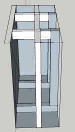
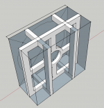
Your bracing looks nice but complicated. Perhaps try a simple cross that goes top to bottom and side to side (2 pieces with middle notch to snap together). Make the cross almost touching the magnet and use compliant rubber or EVA foam sheets to make contact to magnet with slight pressure. Offset to side enough to clear magnet vent if there is one. Cross should touch and be glued to back and side panels.
So just a little update. I finally got replacement CDs from Dayton, they aren't perfect but definitely better.
The design phase is coming along well. I'll have the 3d models up here for critique soon before I convert them to G-code. School is settled down a little before finals and I moved out of the apartment and into a house. Which means I have a window now to actually get these things done. Good thing I didn't build anything before though because I had to tweak the design to better suit the new living room.
Quick question, the SEOS-12, does it need a bit of breathing space on the baffle or can I put it right close to the woofer below it?
Thanks
Shawn
Last edited:
For crossover design, the closer the better. 1/4" - 1/2" visible gap on the front is adequate since there is enough wood hidden behind the driver flanges.
Also, consider bracing the front baffle to the rear panel with a cross brace stick centered right between the drivers. It makes a huge SQ difference because that is a weak location on the front baffle due to the two large driver holes in the baffle.
Also, consider bracing the front baffle to the rear panel with a cross brace stick centered right between the drivers. It makes a huge SQ difference because that is a weak location on the front baffle due to the two large driver holes in the baffle.
Is someone able to tell or show me the directivity / polar of a 12" woofer? I am trying to determine the height of the speaker and where the vertical sweet spot is between the woofer and the SEOS waveguide.
Thanks
Shawn
All woofers are different. Things like cone depth, etc. will affect the directivity.
Theoretically the response is 6 dB down when ka = PI. Since k = 2 Pi freq / c, the directivity will be 45 degreeswhen freq = speed / D ,where D is the diameter of the source. From this the directivity will be 45 degrees for a 12" loudspeaker at 1100 ft/s / 1 ft = 1100 Hz.
Best is to actually measure the response.
The vertical sweet-spot is highly dependent on the phase difference between the two drivers at the crossover. This phase is sensitive to all of the aspects of both drivers and the crossover and represents one of the more difficult things to get right, especially between a horn and direct radiator. It is so sensitive to phase that most models will not be accurate enough. You have to use real data.
At the crossover there will be a main lobe with two very deep nulls along the line joining the two drivers. This nulls should be equally spaced above and below the listening axis. The width of the lobe at this frequency depends on the driver spacing where more distance means a narrower lobe. This lobe also gets narrower the higher in frequency the crossover point is.
Thank you Dr. Geddes.
My design is almost complete. I have a question about box dimensions and nulls. My internal box dimensions are in cm.
Width 31.4
Depth 16
Height 34
My crossover is likely to be around the 1200hz. Are these internal box dimensions likely to cause any nulls? How does that work?
Thanks
Shawn
My design is almost complete. I have a question about box dimensions and nulls. My internal box dimensions are in cm.
Width 31.4
Depth 16
Height 34
My crossover is likely to be around the 1200hz. Are these internal box dimensions likely to cause any nulls? How does that work?
Thanks
Shawn
If you are talking about modes and resonance within the box then yes you will get them unless your internal dimensions are less than half the wavelength of the crossover frequency. But that's what absorption is for. Waste cotton / denim insulation like ultratouch works well.
Box dimensions are mostly irrelevant. Box construction matters a lot. Cross bracing, joint rigidity, panel absorption, but the actual dimension don't matter very much. No matter what the dimension are there will always be the same number of modes in a given band as long as the volume remains the same.
Thank you
The 12" Dayton drivers I'm using have a foam ring around the woofer. I'll be using a front baffle that is 1/2" higher than the woofer, and rounding over flush to the inside edge of the foam. Since it's such a small round over, is this a very early source of diffraction?
My main question is that since learning that the usual 3/4" round over of the cabinet edges is not very effective, whereas a 3" is, is it worth the effort to 3" round over the cabinet edges if there is already an early source of diffraction around the woofer?
Thanks
Shawn
I think it's easy to get so caught up in what theoretically is or isn't good, or what is and isn't measurable that you may never actually do anything.
I seriously doubt anyone could hear the difference between a 1" or 3" roundover on the front baffle in a blind test. 3/4" is a smallish roundover, up to 1.25" is easily doable and quite a bit bigger, but you'll want to have. A double thickness front baffle to accommodate it
This is the 1.25" radius front baffle on my latest project
Sent from my iPhone using Tapatalk
I seriously doubt anyone could hear the difference between a 1" or 3" roundover on the front baffle in a blind test. 3/4" is a smallish roundover, up to 1.25" is easily doable and quite a bit bigger, but you'll want to have. A double thickness front baffle to accommodate it
An externally hosted image should be here but it was not working when we last tested it.
This is the 1.25" radius front baffle on my latest project
An externally hosted image should be here but it was not working when we last tested it.
Sent from my iPhone using Tapatalk
It is difficult to impossible to trace measureable and/or audible effects to diffraction, so any specific question, like the one posed here, will be difficult to impossible to answer. What I have found is that minimizing all forms of diffraction leads to impressive perceptual results. Pinpointing any single improvement among the many would be impossible. But you have to remember that this includes all diffraction, not necessarily just that from the speaker itself. Nearby objects like equipment enclosures and the like also have significant effects. Unless one goes to the extreme of minimizing all local diffraction on or near the speakers, subtle changes, like the one proposed, will most likely be lost in the mix.
Thank you both. I agree Javad that the theory can take up a lot of time. I enjoy it though, but I chuckled when I read that, it's very relevant.
And thank you Dr. Geddes, I had a feeling that was your perspective, I just wanted to be sure.
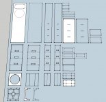
So just an update. My design is more or less done. I'm just on cnczone.com right now getting some advice and making sure what I'm doing is right. This is my first time designing anything for cnc. But the dimensions of the enclosure are pretty set. I'm just making sure my cut lines are correct. In the meantime I am organizing the file so I can post some pictures on here of the enclosures and get some feedback. I'll probably have that posted in the next few hours.
Shawn
And thank you Dr. Geddes, I had a feeling that was your perspective, I just wanted to be sure.
So just an update. My design is more or less done. I'm just on cnczone.com right now getting some advice and making sure what I'm doing is right. This is my first time designing anything for cnc. But the dimensions of the enclosure are pretty set. I'm just making sure my cut lines are correct. In the meantime I am organizing the file so I can post some pictures on here of the enclosures and get some feedback. I'll probably have that posted in the next few hours.
Shawn
Last edited:
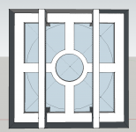
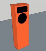
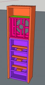
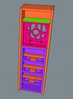
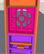
Ok, I spent the afternoon making a 3D image of the speaker, It's not totally accurate but enough to get the idea. The speaker itself is coloured so you can tell the different parts. The lime green between panels is a visco elastic layer of green glue. The box with the woofer kind of 'floats' in a layer of green glue. But it is sealed in tight on all sides. Contrary to the 3D image all the outside edges are rounded over and the joints are lap joints not butt joints.
Just wanted to get this on here today like I said I would. I'll update it more in the coming days.
Let me know what you think!
Shawn
Just wanted to get this on here today like I said I would. I'll update it more in the coming days.
Let me know what you think!
Shawn
Attachments

Last edited:
- Status
- This old topic is closed. If you want to reopen this topic, contact a moderator using the "Report Post" button.
- Home
- Loudspeakers
- Multi-Way
- SEOS / Dayton 2 way