Matthew, I am following all this with interest. I expect to learn lots here.
But I think I'm going to bed soon.
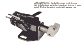
But this thread did remind me of those old PiezoElectric record pickups though. I'm naturally old enough to have used one...This was before CD and MP3 you understand. They sounded pretty good and didn't need much equalisation, but definitely low end.
Unlike magnetic coil cartridge devices, which are called Constant Velocity, they are constant amplitude. Electrically, they would only drive a very high impedance around 2 MegaOhm IIRC.
This ancient device had a stylus you could turn over to play either microgroove LPs or the ancient fatter grooved Shellac 78s which were originally played on "Wind and Grind" record players, called that due to the old bamboo stylus and mechanical horn arrangement driven by clockwork in the 1920s.
In fact, most of the old Louis Armstrong records from the 1920s are copies off 78s. Crackle comes free.
Thought I'd share. Goodnight.
But I think I'm going to bed soon.
But this thread did remind me of those old PiezoElectric record pickups though. I'm naturally old enough to have used one...This was before CD and MP3 you understand. They sounded pretty good and didn't need much equalisation, but definitely low end.
Unlike magnetic coil cartridge devices, which are called Constant Velocity, they are constant amplitude. Electrically, they would only drive a very high impedance around 2 MegaOhm IIRC.
This ancient device had a stylus you could turn over to play either microgroove LPs or the ancient fatter grooved Shellac 78s which were originally played on "Wind and Grind" record players, called that due to the old bamboo stylus and mechanical horn arrangement driven by clockwork in the 1920s.
In fact, most of the old Louis Armstrong records from the 1920s are copies off 78s. Crackle comes free.
Thought I'd share. Goodnight.
Attachments
I remember listening to records as a child back in the 80s , i did really like the warm, comforting & natural sound of vinyl, it was just easy to listen to, and the crackles never seemed overly intrusive for some reason ... Not sure if our player used magnetic pickups or piezo though ...
I did have the opportunity to work on some piezo based ceramic & crystal communications grade microphones for some friends back in the days.. I remember those required a preamp with an extremely high input impedance in the low megohms range .......... Sort of like the modern piezo based "contact" microphones that musicians are using now on anything from a violin, to an upright bass, to a guitar to a banjo or ukelele or even a piano....They are said to sound their very best when used with very high impedance preamps ............Anyway, piezos are very useful yet very affordable devices !
check out the video , this guy entertains me =P
https://www.youtube.com/watch?v=Gkezlp-eI-I
Goodnight!
... Not sure if our player used magnetic pickups or piezo though ...I did have the opportunity to work on some piezo based ceramic & crystal communications grade microphones for some friends back in the days.. I remember those required a preamp with an extremely high input impedance in the low megohms range .......... Sort of like the modern piezo based "contact" microphones that musicians are using now on anything from a violin, to an upright bass, to a guitar to a banjo or ukelele or even a piano....They are said to sound their very best when used with very high impedance preamps ............Anyway, piezos are very useful yet very affordable devices !
check out the video , this guy entertains me =P
https://www.youtube.com/watch?v=Gkezlp-eI-I
Goodnight!
Last edited:
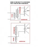
Oh, and i thought this sketch might be useful for the sake of this discussion ... This is a schematic of what is contained within Krafty's LeSon brand piezo tweeter.
It is one or the other (out of the two arrangements in the sketch) and they both accomplish the same goal..
It is one or the other (out of the two arrangements in the sketch) and they both accomplish the same goal..
Attachments
Hi,
The point is not the alleged impedance of the transformers,
its the reflected impedance of the capacitance of the piezo
and the necessarily very low subsequent voltage rating.
rgds, sreten.
DCR of transformer windings usually don't tell you much, but
here I'm prepared to concede that said windings are also
effectively the series resistance I said you must have.
Last edited:
Hello Sreten,
Your concern for the voltage ratings of the piezo itself are valid because as we know overly high voltages will definitely damage a piezo element.. However lets keep in mind that this particular arrangement calls for an unusually high crossover point to offset the "tilt" in response that the transformer creates, and that compensated "tilt" is how we still get decent response down to 5khz even though 4.7uf at 4ohms= 8500hz ...
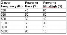
Now if we also take into consideration the distribution of power in music it becomes clear why the LeSon wont so easily self destruct when music is played through it as long as there is a proper crossover network used... Take a look at the picture i have attached to this message, it gives you an idea of how power is typically distributed within the sound spectrum, and with a crossover point of 8500hz you can see that much less than 10% (probably closer to 5%) of the power would be reaching the LeSon tweeter or any other tweeter crossed over at 8500hz for that matter...
Your concern for the voltage ratings of the piezo itself are valid because as we know overly high voltages will definitely damage a piezo element.. However lets keep in mind that this particular arrangement calls for an unusually high crossover point to offset the "tilt" in response that the transformer creates, and that compensated "tilt" is how we still get decent response down to 5khz even though 4.7uf at 4ohms= 8500hz ...
Now if we also take into consideration the distribution of power in music it becomes clear why the LeSon wont so easily self destruct when music is played through it as long as there is a proper crossover network used... Take a look at the picture i have attached to this message, it gives you an idea of how power is typically distributed within the sound spectrum, and with a crossover point of 8500hz you can see that much less than 10% (probably closer to 5%) of the power would be reaching the LeSon tweeter or any other tweeter crossed over at 8500hz for that matter...
Attachments
Now, to provide some contrast on this subject (piezos/voltage/distribution) we can compare the above described LeSon arrangement with the arrangments that most people have used with standard piezos over the years by running them with no crossover or network whatsoever with the exception of perhaps a series resistor ...Ok , so what do we know about this?... We do know that high voltages will damage piezo elements, and the truth is that a series resistor does NOTHING to prevent high voltages from reaching the piezo element and harming it (note: if it is just a raw piezo element with no transformer it is a "voltage device") ... A resistor impedes current not voltage......So when it comes to amplified full range music and a kick drum sound for example (or any other loud bass sound) a massive amount of voltage will be imposed upon the piezo element used in this system potentially damaging it, and it doesn't matter that the sounds in the bass range are not within the piezos working range, it is still voltage .... Its amazing that these piezos are rugged enough to withstand the full spectrum of audio and it's associated voltages being imposed across it at all, for any amount of time.... ..
Needless to say feeding the piezo a high-passed signal (versus full range) will increase the reliability and lifespan of the piezo significantly even if the high-passed signal is stepped up a bit..
For anyone who is under the impression that bass sounds cannot damage your piezo take a look at the following video that i am posting the link for ... Hooked up to the "mains" ,Thats 50hz (a deep bass note) at high voltage, and the piezo doesn't last long at all, actually its pretty amazing that it lasted for even those few seconds ...
Piezo Tweeter BLOWOUT - YouTube
Last edited:
Everyone interested in this subject should watch the following video ... It is EXTREMELY PERTINENT! I am glad to have just found it ...
Krafty, does that (transformered) unit in the video resemble your LeSon? His tweet is an 8 ohm impedance instead of 4 ...
I recognize the other unit, the rectangular one without the transformer , it is either a Goldwood 1016 or a GRS brand 1016.
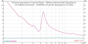
Sreten, this guy performs an impedance sweep on both units and the results tell us a lot about how the impedance curve can look, at least on the primary side of the transformer.
Custom Piezoelectric Tweeters - Impedance Treated (Measurement) - YouTube
I am glad to have just found it ... Krafty, does that (transformered) unit in the video resemble your LeSon? His tweet is an 8 ohm impedance instead of 4 ...
I recognize the other unit, the rectangular one without the transformer , it is either a Goldwood 1016 or a GRS brand 1016.
Sreten, this guy performs an impedance sweep on both units and the results tell us a lot about how the impedance curve can look, at least on the primary side of the transformer.
Custom Piezoelectric Tweeters - Impedance Treated (Measurement) - YouTube
Attachments
Last edited:

System7,
I contacted the guy who does the coil filters for me, and I asked about he doing a 1mH/50R filter like you said.
His answer is:
I only work with wire number 17 (1,15 milimeter). With that wire, it would only give a resistance of 0,342 ohms.
So what do you suggest me to do?
I contacted the guy who does the coil filters for me, and I asked about he doing a 1mH/50R filter like you said.
His answer is:
I only work with wire number 17 (1,15 milimeter). With that wire, it would only give a resistance of 0,342 ohms.
So what do you suggest me to do?
Can't find exact part values... so for the capacitor, I will be using a 0.51uF... is that ok? As for the resistor, it will be either 3R9 or 4R7... which one should I go for? These resistor are surely expensive, like 2 USD each.
The coil... I realize I will have to manufacture one myself. 22 AWG wire? Is there any tutorial to achieve 1mH/50R ?
I am also dropping the PCB project, since I see that 20-way terminal bars are more convenient for a project like this (Troels Graveseen - by the way, WHAT A project!).
The coil... I realize I will have to manufacture one myself. 22 AWG wire? Is there any tutorial to achieve 1mH/50R ?
I am also dropping the PCB project, since I see that 20-way terminal bars are more convenient for a project like this (Troels Graveseen - by the way, WHAT A project!).
Ahh, ok, so the one tweeter in that guy's video is a LeSon TLX-2 you say .. very cool ... do you like the way your TLX-2s sound in your living room? What sort of network did you use with them?
Hopefully your 4ohm LeSons have a primary impedance that is as flat as what the guy demonstrated in the video... The measurement of his LeSon was extraordinarily flat .. Since his and yours are the same brand with the same circuit we could assume that your impedance curve is likely to be at least reasonably flat....
In case you guys didn't catch it The LeSon's curve is the light blue curve on the bottom which he calls "treated" (meaning it includes the transformer)....
The other curve, the wild looking one (light pink) is the "untreated" 1016 style Piezo..
The flat impedance curve of the LeSon is a good thing because it makes designing networks for it easier, more straightforward, and more likely to have predictable results
Hopefully your 4ohm LeSons have a primary impedance that is as flat as what the guy demonstrated in the video... The measurement of his LeSon was extraordinarily flat
.. Since his and yours are the same brand with the same circuit we could assume that your impedance curve is likely to be at least reasonably flat.... In case you guys didn't catch it The LeSon's curve is the light blue curve on the bottom which he calls "treated" (meaning it includes the transformer)....
The other curve, the wild looking one (light pink) is the "untreated" 1016 style Piezo..
The flat impedance curve of the LeSon is a good thing
because it makes designing networks for it easier, more straightforward, and more likely to have predictable results Attachments

Hi Matthew...
I am going to check what I did way back, when I put together that cabinet. I am curious to see if that LeSon is indeed 8 ohms. I remember putting just one capacitor for protection, nothing more. I did not use any crossover on that box. I will take a picture of the cabinet.
I must confess I am still in the dark when you say that the curve is flat. In fact, I don't know how things are suppose to be, that is why I keep asking advice. I assume a curve being flat is good upon your smile. Ok, from the graph I see the flat line. So, in theory all speakers are supposed to be flat like in this graph?
In a few minutes I will post more info.
Last edited:
Krafty ,
Yes , you are correct , a flat impedance curve is generally a very good thing and easy to work with.
About your woofer, I have a question, do you have a response graph for it? or do you have a way to hook it up to an amp and run a sine sweep through it?
You may find out that it has a nice natural response rolloff right exactly where you want it (3khz-5khz right where your tweeter picks up) without using any series coil at all ... That would be called running the woofer "dry" (no crossover network at all) and sometimes that method works really well depending on the characteristics of the woofer...
The reason i mentioned this is because the 1mh coil (or inductor or choke whatever you choose to call it) you are discussing would give you a low pass crossover point of 600hz on a 4ohm woofer which would be fine in a 3-way system where you have a midrange driver handling the 600hz-4khz range but i'm pretty sure that what you had in mind was a 2-way system, is that correct? In that case you will need the woofer to reproduce sounds all the way up to 4khz which would require using a much smaller value coil such as .16mh or just running the woofer "dry"..
Yes , you are correct , a flat impedance curve is generally a very good thing and easy to work with
.About your woofer, I have a question, do you have a response graph for it? or do you have a way to hook it up to an amp and run a sine sweep through it?
You may find out that it has a nice natural response rolloff right exactly where you want it (3khz-5khz right where your tweeter picks up) without using any series coil at all ... That would be called running the woofer "dry" (no crossover network at all) and sometimes that method works really well depending on the characteristics of the woofer...
The reason i mentioned this is because the 1mh coil (or inductor or choke whatever you choose to call it) you are discussing would give you a low pass crossover point of 600hz on a 4ohm woofer which would be fine in a 3-way system where you have a midrange driver handling the 600hz-4khz range but i'm pretty sure that what you had in mind was a 2-way system, is that correct? In that case you will need the woofer to reproduce sounds all the way up to 4khz which would require using a much smaller value coil such as .16mh or just running the woofer "dry"..
The woofer is a car speaker. Google for "4HTS400" and you will see the babe. I liked their sound. Someone gave them to me, so I am reusing them. This project is for a computer speaker, not a living room stereo, so that is why I am taking those car speakers. The downside is that the manufacturer is a "no-go" business, since they discontinued the product and don't even have a legacy catalog download. (Oh, by the way, you suck Hinor, you suck... if you're reading this.)
I don't know if I could measure that using my soundcard with a software. Suggestions? This is not a huge woofer, it is a 4 inch.
I don't know if I could measure that using my soundcard with a software. Suggestions? This is not a huge woofer, it is a 4 inch.
Ok, so back with more info...
The TLX-2 LeSons in my living room, I measured them. Each of them gave me a value of 15 ohms, measuring straight through their terminals. It dates back to 2003 these ones, so there might be some change in there from the manufacturer.
The setup I chose back in that time, ignoring the whole audio crossover thing, was just to put a 4.7uF bipolar capacitor in series with the positive. The funny thing is that when you measure WITH the capacitor, it goes down to 4 ohms, and not 15 anymore.
These new LeSons I have are made in USA. Strange isn't it? The ones I just measured that gave me 15 ohms were made in Brazil.
I want to share two pictures with you...
(1) The first one is the project I am talking about in this thread. The tuned PC speaker (that will work with an old Philips AS-325 stereo).
(2) The second is the project from 2006 I did, which was to renew my living room speakers. Well, I ignored most of the tech audio part, so it's plain. It sounds alright after a bit of tweaking the equalization through the stereo (I generally remove the medium frequencies). But I had been wondering why this set was too bright - I guess now I know - because of these piezos not tweaked.
Thats a fine looking little 4 inch midbass driver. You said someone gave them to you? For the price of free thats a good score!, my kinda deal ! hehe
Sorry to hear that Hinor went out of business, and it is a shame that they didn't leave much information to work with in regards to their drivers but i think that is commonplace for many car audio brands, they often don't make full lists of specs and charts & such things available at all ..
On the other hand im really glad to hear that LeSon is still in business and then to hear that they are manufacturing in the United States is a big surprise for me! If they truly are manufacturing them here now i wish they would make them available for purchase here as well .
About your home speaker system, you are correct, the reason it sounds overly bright is because the tweeter is more sensitive and is playing however many decibels louder than your woofer. Your woofer is unable to keep up with your tweeter, or in other words the tweeter is just too "hot" and will need to be "padded" down (pad is another word for attenuate). A series resistor before the cap should do the trick. So the order would be: amp---->resistor---->cap---->LeSon ....
Also, just so you know a series cap actually is a type of crossover, just a very simple crossover, often referred to as "1st Order" .. It may be simple, but its very effective and sometimes it is all that you need
You said someone gave them to you? For the price of free thats a good score!, my kinda deal ! heheSorry to hear that Hinor went out of business, and it is a shame that they didn't leave much information to work with in regards to their drivers but i think that is commonplace for many car audio brands, they often don't make full lists of specs and charts & such things available at all ..
On the other hand im really glad to hear that LeSon is still in business and then to hear that they are manufacturing in the United States is a big surprise for me! If they truly are manufacturing them here now i wish they would make them available for purchase here as well .
About your home speaker system, you are correct, the reason it sounds overly bright is because the tweeter is more sensitive and is playing however many decibels louder than your woofer. Your woofer is unable to keep up with your tweeter, or in other words the tweeter is just too "hot" and will need to be "padded" down (pad is another word for attenuate). A series resistor before the cap should do the trick. So the order would be: amp---->resistor---->cap---->LeSon ....
Also, just so you know a series cap actually is a type of crossover, just a very simple crossover, often referred to as "1st Order" .. It may be simple, but its very effective and sometimes it is all that you need
Last edited:
Krafty,
If you wanted to get an idea of what the actual effective response is of your woofer its pretty easy to do, and yes you can use your soundcard to do it as long as it is hooked up to a small amp ... Hook the amp up to the woofer and be sure to flatten or turn off any equalizers or bass/treble adjustments ... Use the signal generator function in winISD to play tones and sweeps through the woofer .. Your main concern should be the 3000-8000hz range .... Even though Hinor claimed that their woofer is effective up to 8000hz you may find that the output really starts to drop off before getting to 8000hz...
If you wanted to get an idea of what the actual effective response is of your woofer its pretty easy to do, and yes you can use your soundcard to do it as long as it is hooked up to a small amp ... Hook the amp up to the woofer and be sure to flatten or turn off any equalizers or bass/treble adjustments ... Use the signal generator function in winISD to play tones and sweeps through the woofer .. Your main concern should be the 3000-8000hz range .... Even though Hinor claimed that their woofer is effective up to 8000hz you may find that the output really starts to drop off before getting to 8000hz...
(1) Concerning the resistor from my living room setup, 22R/20W would do it? I may replace the capacitors as well, for polyesters ones.
(2) WinISD, yes, I have used this software to calculate this small box. I have an issue with the amp though, it has a hardware built-in 3 way eq. Should I set all levels on medium level or bring everything down?
(2) WinISD, yes, I have used this software to calculate this small box. I have an issue with the amp though, it has a hardware built-in 3 way eq. Should I set all levels on medium level or bring everything down?
Last edited:
Krafty ,
22ohm could be a good place to start, and if that value attenuates the tweeter too much then try a 10 ohm resistor ... If 10 ohms makes the tweeter too loud then try 15.... and so on ... Adjust to your taste until you find a nice balanced sound without having to use so much EQ .. The 20w rating should be fine..
Switching to poly caps is a good idea, they are generally considered a better choice for crossover work ...
...and about using a signal generator and your amp for testing, yes, you got it , just set all of the EQ adjustments to the "0" mark, or the center ..,.
Last edited:
- Status
- This old topic is closed. If you want to reopen this topic, contact a moderator using the "Report Post" button.
- Home
- Loudspeakers
- Multi-Way
- Please check out my final circuit X/O with piezo