Shining a light is attempting some sort of analysis,
rather than choosing who you'd like to agree with.
No, I am not choosing anything. Are you saying that the datasheet shows a false curve, and that I have to acquire that by measuring by myself. Is that right? Because I see that there is an impedance curve in there. I guess that you're saying I have to "extract" that curve myself...
I'm not sure I follow what that one does at all, particularly the 0.47uF in parallel with 4R which is insignificant next to 22R. Shouldn't there be a small shunt resistor across the piezo, or are you assuming it's built in to the device?
Isn't the shunt resistor the thing that is being put in question by some folks here, and also because this is not a plain standard piezo?
Have you measured the DC resistance of this tweeter with a multimeter, krafty? That would tell me something about what's inside it. Though if there's a coupling capacitor built in, that might confound the measurement.
In which conditions should I measure? Is it measurable by only using the multimeter, without any load? Measuring directly wired to the amp? I need some help here...
Thanks for the articles I will take a look at them.
I think krafty said he'd fried one already, so maybe a bit of disassembly is in order here.
It's the upside of breaking things, that you find out how they work.
Yes, I have one broken now.
A new replacement just arrived today.
Well, crack the broken one open. Gently. See what's inside!
I think you can just measure resistance with a multimeter here. Just the tweeter in isolation. These things are immune to DC as far as I know.")
You've got some known wirewound resistors lying around, by the sound of it. You can practise your testing technique on those if the meter is unfamiliar to you.
Can't always find stuff on the internet, you know. Sometimes YOU have to become the expert!
I think you can just measure resistance with a multimeter here. Just the tweeter in isolation. These things are immune to DC as far as I know.
You've got some known wirewound resistors lying around, by the sound of it. You can practise your testing technique on those if the meter is unfamiliar to you.
Can't always find stuff on the internet, you know. Sometimes YOU have to become the expert!
Last edited:
System7, I only see the coil, that is all. There is no capacitor or anything. I have posted pictures on page 4, you can have a look too.
I have a multimeter, I used it today to measure my car battery. I am familiar with it.
Should I just set it to the "ohm" measuring and choose like 200R. Measuring + and - gave me 04.2
I have a multimeter, I used it today to measure my car battery. I am familiar with it.
Should I just set it to the "ohm" measuring and choose like 200R. Measuring + and - gave me 04.2
AW, sorry mate. I missed those HUGE pictures somehow. Ever thought of shrinking them before posting? They were hard to view!
You set the meter to the smallest range consistent with what you are measuring. 200R is right for low audio resistors. Good meters go up to 2M at least. That is really high resistance that you might get measuring across your hand.
OK, so the primary coil is 4 ohms resistance. OK, that's about what we were hoping I think. I think that means it steps UP the voltage to the piezo device. The piezo side of the transformer has more windings, I'd guess.
Since you've got efficiency to spare here, you could still shunt a resistor across it I reckon. Maybe 4-10 ohms. But the circuit from the manufacturer makes a sort of sense now, even if I don't believe the exact values of attenuation they are getting.
Now you're gonna tell me the manufacturers circuit didn't work, I guess! But you will need some significant resistance (like 15R in series) to take it above 4 ohms with a 4.7uF capacitor also in series. 4 ohms load would stress an amplifier.
Last edited:
You set the meter to the smallest range consistent with what you are measuring. 200R is right for low audio resistors. Good meters go up to 2M at least. That is really high resistance that you might get measuring across your hand.Now you're gonna tell me the manufacturers circuit didn't work, I guess!
The multimeter I have has marks up to 20M. If I position it on 2M, the value I get is 004, measuring the tweeter + and -.
I don't see additional windings on the piezo side.
I actually didn't still test the manufacturers circuit. Well, I did test, with the wrong capacitor (0.47uF). But I will redo this.
But the circuit from the manufacturer makes a sort of sense now, even if I don't believe the exact values of attenuation they are getting.
So, have a shunt or not?
But you will need some significant resistance (like 15R in series) to take it above 4 ohms with a 4.7uF capacitor also in series. 4 ohms load would stress an amplifier.
15R substituting the 22R indicated? 15R as an additional resistor in series?
Selecting the right range on a meter gives you the best accuracy. The idea is to use the biggest testing current that is safe.
Back to the Piezo. I'd use a 4 ohm shunt resistor to give it a good steady sort of impedance to start with. It will never rise above 4 ohms that way even if the transformer presents a very high impedance at high frequencies. We are guessing it's gonna actually be 2 ohms with the piezo and 4R resistor in parallel.
Then a series resistor of say 20 ohms decoupled from DC by the series 4.7uF capacitor will become an attenuator with a 1:10 step down, becoming 1:5 in the worst case of the tweeter becoming a high impedance.
Seems simple enough. See how it sounds.
You can fiddle with values later.
Last edited:
Hi system7...
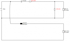
Ok, I guess this would be it?
I need to understand if the part you say "decoupled from DC by the 4.7uF" is right in this circuit, since decoupling caps are placed from hot to ground...
I also contacted again the manufacturing questioning their numbers. It will be interesting what they say.
Update: Just saw you posted a circuit. The difference is that the cap is before the 20R resistor. Doesn't that go against the manufacturer's order of components?
An externally hosted image should be here but it was not working when we last tested it.
Your circuit isn't the same thing. It will burn low frequency power through the wirewound resistors. Which is wasteful. I've a feeling it would let more low frequencies through to the tweeter too, maybe even resonate with the coil.
This tweeter only has significant output above 5kHz, so the capacitor goes where I drew it. Actually, if you exchanged the 22R and 4.7uF in my diagram, it wouldn't make any difference.
BTW, this needs to be a non-polar electrolytic capacitor, preferably a MKT polyester or MKP polypropylene.
This tweeter only has significant output above 5kHz, so the capacitor goes where I drew it. Actually, if you exchanged the 22R and 4.7uF in my diagram, it wouldn't make any difference.
BTW, this needs to be a non-polar electrolytic capacitor, preferably a MKT polyester or MKP polypropylene.

I've been doing this stuff, sometimes for a living, mainly for fun, for 40 years, so I doubt if I've messed up completely here.
This is quite exciting though. I've never used a piezo myself. I think the whole filter might be improvable eventually, but this is a start. What you call proof of concept.
We ought to be able to get the bass sounding reasonably smooth too. I don't really consider 0.11mH to be much of a filter. You can do better.
Oh, by the way, 20W wirewound is definitely over the top for the 4 ohm. It won't need anything near that. 10W will do. And the 22R, which carries more current and voltage, will act like a fuse if it catches fire, so won't damage anything. But I suppose 20W is justified there if you drive it hard.
Last edited:
system7,
The inductor was calculated using the speaker values in the crossover calculator. Unfortunately I have no ways of wiring an inductor myself, theses ones I have I bought it for something like 17 USD a pair.
Please look at the first post, to see that I came up with that value, following what the calculator said. Are you saying that that calculator isn't to be used as reference? Or are you just feeling it ?
You've done this for 40 years, that is weird, you don't look past 30 years old on your avatar......
Last edited:
Those wretched calculators lead people up some very strange garden paths. I suspect they are sponsored by inductor makers to flog components.
Filters don't really work like that at all, because drive units don't have a flat response. We really want to get you onto Troels Gravesen.
As for my lack of ageing, and uncanny forum resemblance to hilarious Ubergeek Robert Heron, I guess I must be a magician.
Hmm...Robert is putting on weight!
Filters don't really work like that at all, because drive units don't have a flat response. We really want to get you onto Troels Gravesen.
As for my lack of ageing, and uncanny forum resemblance to hilarious Ubergeek Robert Heron, I guess I must be a magician.
Hmm...Robert is putting on weight!
Last edited:
The parallel resistor is not a bad idea, it should insure that we have a more-so flattish impedance response Based on the most recent sketch that was posted the series 4.7uf is going to have to be changed to a different value now though since it is seeing a 22ohm load instead of a 4 ohm load so in order to maintain the same crossover point the value for that cap will have to be around .8uf (or you could try caps in the ranges of .5uf to 1uf in order to "season to taste" to get the sound you want ..)
However, another option here would be to reverse the positions of the 20ohm (or 22ohm) resistor with the series capacitor, but in this case the cap's value would have to be doubled to 10uf in order to maintain LeSon's suggested crossover point ... Two 4.7uf caps could be "piggybacked" to get close enough at 9.4uf.
Based on the most recent sketch that was posted the series 4.7uf is going to have to be changed to a different value now though since it is seeing a 22ohm load instead of a 4 ohm load so in order to maintain the same crossover point the value for that cap will have to be around .8uf (or you could try caps in the ranges of .5uf to 1uf in order to "season to taste" to get the sound you want ..)However, another option here would be to reverse the positions of the 20ohm (or 22ohm) resistor with the series capacitor, but in this case the cap's value would have to be doubled to 10uf in order to maintain LeSon's suggested crossover point ... Two 4.7uf caps could be "piggybacked" to get close enough at 9.4uf.
An externally hosted image should be here but it was not working when we last tested it.
4.7uF into 22 or 26 ohm load is going to be a very low crossover altogether. I'd think it's -3dB below 2kHz. So far I think the response of the piezo will be almost free-running, which means it's -3dB around 6kHz.
In other words, 4.7uF is way over the top really. There may be scope to reduce it later.
Swapping a resistor and capacitor round makes no difference at all, if you don't mind me pointing it out. The overall impedance R + 1/jwC is the same as 1/jwC + R. Notice my use of the engineer's j rather than the mathematician's i. We are, after all, PROFESSIONALS.
by the way guys, the piggybacked cap and resistor components that i included in a previously posted schematic are nothing more than a little bit of equalization ... Adding a RELATIVE boost to the highest frequencies reproduced by the LeSon by attenuating (via the resistor) everything below the high pass filter defined by the value of the cap ....Of course if using only a 4ohm resistor in the network the effect will hardly be noticeable, it will require a larger resistor value to make the effect more apparent ... It no big deal and its nothing mysterious, and it is by no means necessary but can add a little bit of "air" and sparkly high end response if that is what is preferred .. It can help you approach a sound more similar to what you would want for home audio use or car audio use instead of the traditional harsher PA compression driver sort of sound..
system7, which cap value do you recommend...
We really don't know yet. Don't these things just ignore the low frequencies?
But at a later stage, given it has around 12dB/octave natural rolloff, we might reduce the capacitor if we want a steeper 18dB per octave rolloff for some reason. As Matthew just added there are a few tricks to pull here for the perfect sound.
Ah, don't worry about it at the proving stage.
And anyway, I did say I'm new to piezos too, didn't I?
System7 you should try some piezos out some time, i think you would enjoy the challenge of them, they can be tricky but fun .. 
For example , here is something else that is counterintuitive and zany .... Take a look at what LeSon is suggesting to us ... A 4ohm load with a 4.7uf series cap ... If you put those figures into a crossover calculator you end up with a crossover point of around 8500hz! Which doesn't seem to make any sense to someone who is expecting to get strong and fairly flat output down to 5000hz but what i have found from experience is that adding a step-up transformer to a piezo can create quite a significant tilt up on the bottom end the piezo's range, and as it turns out the series cap has a shallow enough curve (1st order =6db per octave) to almost perfectly compensate and correct the response. Cool eh?
For example , here is something else that is counterintuitive and zany .... Take a look at what LeSon is suggesting to us ... A 4ohm load with a 4.7uf series cap ... If you put those figures into a crossover calculator you end up with a crossover point of around 8500hz! Which doesn't seem to make any sense to someone who is expecting to get strong and fairly flat output down to 5000hz but what i have found from experience is that adding a step-up transformer to a piezo can create quite a significant tilt up on the bottom end the piezo's range, and as it turns out the series cap has a shallow enough curve (1st order =6db per octave) to almost perfectly compensate and correct the response. Cool eh?
- Status
- This old topic is closed. If you want to reopen this topic, contact a moderator using the "Report Post" button.
- Home
- Loudspeakers
- Multi-Way
- Please check out my final circuit X/O with piezo