Although the impedance for that 8 ohm LeSon curve in the graph shown is not ideally flat, it can be useful ...
You may say that this curve may be "all over the place" but in my opinion it is a vast improvement over a standard untreated piezo (no transformer step up) that can have a fluctuating impedance that swings from 50 ohms to 1000 ohms, thats a BIG difference! This much scaled down curve should be a lot easier to work with ..
You may say that this curve may be "all over the place" but in my opinion it is a vast improvement over a standard untreated piezo (no transformer step up) that can have a fluctuating impedance that swings from 50 ohms to 1000 ohms, thats a BIG difference! This much scaled down curve should be a lot easier to work with ..
Last edited:
The choices made in values and how to arrange the resistors
could make the difference between a scooped response ,
Hi,
Sorry but that is completely wrong given the driver
is measured using voltage drive. If is was measured
using current drive (which it clearly isn't) and had
the response given (which it wouldn't) then there
is theoretically parallel could induce a dip, but to
get there you have to get something very wrong.
The only question is how much additional peaking
using an L-pad attenuator will introduce, there
will always be some, but here easily minimal.
rgds, sreten.
Last edited:
Sreten,
Keep in mind this is not a normal Piezo, it is not just a voltage device considering that we are actually driving the primary windings of a transformer ...
Do the math for yourself, if we have a series resistor followed by a parallel resistor forming an attenuator network the attenuation will have more effect upon the range of high impedance around 7khz to 10khz as opposed to the lower impedance of the areas around 5khz and 20khz making the frequency response look different than that which is shown in the LeSon graph ....
The typical (not a LeSon) piezo makes a good example of this:
This effect is the reason why standard (with no step-up) piezos begin to roll off on the top end if you put a high value series resistor on them .... A standard piezo has a falling impedance response meaning that typically at 15khz to 20khz (or higher) it's impedance is lower than what it would be at 8khz just like a capacitor, so there is more loss across the resistor at higher frequencies because of a slightly higher current draw of the piezo up there ..... This can be very useful if rolling off the highest frequencies is what a designer is aiming to do ....
If you are trying to achieve the reverse then some parallel resistance could tilt the response the other way because more power goes the piezo where it has lower impedance (up high) and the parallel resistor gets more of the power where the piezo has a high impedance , it is all based on how the Piezo's impedance is related to the resistor that you used .... Thats why i am saying that it can be useful to take this into account ..
However the LeSon clearly doesn't have the impedance response of a typical piezo, and if we are to go with what their graph for that 8 ohm tweeter suggests then the highest impedance within it's working range falls right into the middle (of it's useful range) so being mindful of the way you set up your attenuation network could lift the 7khz-10khz relative to the rest, or could scoop those same frequencies .... Once again, it could be useful depending on what you are trying to achieve .....
Last edited:
System7,
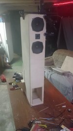
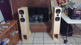
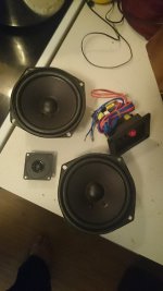
We have these TL cabinets finished..They are based on the $22 dollar (yet surprisingly high quality) Mavin MTM kit ... GREAT RESULTS!! , (much better bass than could be had with these same drivers in a ported cabinet) they are rather large though, so that's the compromise.... The footprint isn't too bad because of the slender tower format, but they are still much larger than a ported cabinet would be for these small drivers ..
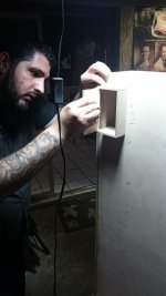
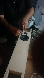
I took some quick and rough measurements with a Dayton measurement microphone and HOLMimpulse software (which is AWESOME by the way and FREE !) .... I wasn't unable to get proper measurements outdoors that day because it was too windy here, and the next day Adam (the guy you see in one of the pics) took the cabinets home, so these measurements will have to do ...
We have these TL cabinets finished..They are based on the $22 dollar (yet surprisingly high quality) Mavin MTM kit ... GREAT RESULTS!! , (much better bass than could be had with these same drivers in a ported cabinet) they are rather large though, so that's the compromise.... The footprint isn't too bad because of the slender tower format, but they are still much larger than a ported cabinet would be for these small drivers ..
I took some quick and rough measurements with a Dayton measurement microphone and HOLMimpulse software (which is AWESOME by the way and FREE !) .... I wasn't unable to get proper measurements outdoors that day because it was too windy here, and the next day Adam (the guy you see in one of the pics) took the cabinets home, so these measurements will have to do ...
Attachments
-
 10153936_240003246205315_1522616852144064222_n.jpg59.5 KB · Views: 116
 -
 10155445_245194995686140_7433810843031406045_n.jpg43.5 KB · Views: 116
 -
 10172692_245214625684177_1370947407857724132_n.jpg31.1 KB · Views: 117
 -
 10176005_245195119019461_4052657975286825588_n.jpg54.6 KB · Views: 111
 -
 10302641_245194972352809_2124592907976102113_n.jpg76.5 KB · Views: 115
 -
 kit-MTM-KLIPSCH-SAMSUNG-ADAM.jpg52.6 KB · Views: 61
 -
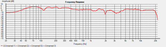 COMBINED RESPONSE-TOTAL.png19.2 KB · Views: 64
Last edited:
Resurrecting this thread just to announce I gave up the project.
Due to the lack of time to finish the project and no consensus among the writers, apart from the fact that since 2012 which is the year I started with this project and not being able to finish this in full 4 years, meant that I will never finish it.
I went and bought a set of EDIFIER RT1000T4 studio monitors.
The speakers are just about the same size I was building, with similar components.
The ironic thing about it is that, the path I was going, would end up more or less in what this manufactured product is done: The trebles are not what I expected to be. They are a bit muffled. They seem to have "proper" tweeters now. But in the computer, I have to equalize them. Just like it was going with the circuit I was elaborating back in 2012/2013.
My wife says that these new speakers have treble enough. This points out that I'm having a problem with my ears right now, and would have been in no position to finish the DIY project anyway that way.
It's ENT problem involving an issue with the Eustachian tube, it closes and stops ventilation so the inner ear is integer, but middle-ear cannot pass through perceivable treble enough, the eardrum is sucked because of negative pressure.
If you are in Brazil and gets interested for the entire DIY package I was doing, I can sell you very cheap. Just send me a message. Thank you.
Around February, with so much stress and built up tension on my mind, I ended up destroying the project to pieces. The drivers fell apart, the magnets literally crushed to pieces like thousands of beans scattered around. The woods were a bit harder... they were MDF but it turned out to flakes as my fury hit the climax.
So this is it. Everybody has a Kurt Cobain day I suppose.
So this is it. Everybody has a Kurt Cobain day I suppose.
- Status
- This old topic is closed. If you want to reopen this topic, contact a moderator using the "Report Post" button.
- Home
- Loudspeakers
- Multi-Way
- Please check out my final circuit X/O with piezo