Hi,
Well I give up given the amount of conflicting
misinformation and conjecture that is here.
This is a forum, where people come in to ask questions and debate.
Forums are not supposed to be a 10 page cook book recipe.
I'm not going to wade through 180 posts
to sort the wheat from the chaff and
reiterate the basics being ignored.
You really may have all the knowledge in the world,
but dealing with people & communication is not your best skill at all.
Your posts are quick & straight, yet you do not point the wrongs,
and don't even realize what is the context (you insisting this was about a car setup).
I haven't seen you pointing what's conflicting and what's misinformation,
just several posts of your with only half of a train of thought.
rgds, sreten.
That sort of foam will hold itself in place.
Thanks for that tip. You see, that was very productive.
This is turning into a rites of passage movie! 
You know, the sort of thing where someone learns it's nice to be clever, but cleverer to be nice.
Anyway back to cabinet damping. There are a lot of ways to do it. With closed box, you usually want some panel damping like rubbery stuff stuck to the sides, top and bottom with aerosol carpet adhesive, and a lump of stuffing not dissimilar to a polyester pillow case inside.
Egg crate foam doesn't actually do much. It's usually used in cheap reflex designs.
Troels explains: Cabinet-damping
Adhesives are a tricky subject. Especially solvent based ones that might interact unexpectedly with the drivers. Troels has some ideas on that too:
Tips and tricks
I don't get fussy about damping these days. I'd happily stick rubber backed carpet to a case if it's lying around. Maybe you've got a use for old pillows too. You probably want the builder's merchant more than the HiFi supplier.
Hi,
I didn't insist it was for a car set up, somebody said it was, several
posts then implied it was, and you didn't correct any of them.
If we are talking skills, then keeping it to the case in question,
detailing the intended use, and your expectations of what
you really want to achieve are sorely lacking.
Fact is given the title you were just asking for it and have
got it, even though your first post looks very reasonable,
and is correct in most respects (in terms of your analysis),
except the treble circuit (and comments) is for a standard
piezo and not one that measures 4 ohms.
No details of the box, bass alignment, intended placement.
However its wrong on the bass end, ignoring driver response
and the the box effects of typical usage, which after 180+
posts is still being ignored. The treble end is still complicated
without knowing the impedance curve and the driver response,
both realistically could be all over the place, unlikely not to be.
Technical people skills is not pandering to people, people who
are wrong are going to get upset if they so choose to do so,
but its their choice to overestimate their veracity of opinion.
It is sorting the wheat from the chaff, and if we were all in the
same room with a whiteboard this really wouldn't take that long.
rgds, sreten.
Last edited:
Egg crate foam doesn't actually do much.
It's usually used in cheap reflex designs.
Hi,
Another one of your cheap throwaway lines that is misleading / wrong.
It doesn't do anything in terms of wall damping and is not
intended to, it is very good acoustic damping, near the best.
The good stuff is very expensive and ideal for lining vented boxes,
especially 4th order bandpass, but it is pretty pointless for sealed.
(Wall damping is addressed seperately.)
rgds, sreten.
A fine example of the sort of crap this thread is littered with.
Last edited:
I didn't insist it was for a car set up, somebody said it was, several
posts then implied it was, and you didn't correct any of them.
Oh yes you insisted, I corrected the first time I read you're saying what a waste that was because the whole thing being about a car... The context of the car popped up because the speaker manufacturer makes these speakers for cars.
except the treble circuit (and comments) is for a standard
piezo and not one that measures 4 ohms.
You still didn't said any word about the piezo datasheet here.
What software do you personally use to measure the tweeter and what measurements would you do to obtain?
Box is 4 liters discounting the MDF, MDF 9mm. The intended placement, etc... I posted a picture of the box here. Not sure about bass alignment though.No details of the box, bass alignment, intended placement.
However its wrong on the bass end, ignoring driver response
and the the box effects of typical usage, which after 180+
posts is still being ignored
Have you seen the midbass details? Why do you say that? You're not for the zobel,
or are you specifically insisting about using a higher air core filter inductor, BSC ?. Please when you state such thing, _tell_ us what is that you're saying.
The treble end is still complicated
without knowing the impedance curve and the driver response,
both realistically could be all over the place, unlikely not to be.
You mentioned an "excellent" piezo article, yet you thrown a bunch of links. I appreciate those links, but where is that piezo article that says it all? About the impedance curve, what software would you personally use?
Technical people skills is not pandering to people, people who
are wrong are going to get upset if they so choose to do so,
but its their choice to overestimate their veracity of opinion.
All I ask is that you make yourself more clear when pointing errors.
it is very good acoustic damping, near the best.
I'm relieved to hear that, since I just spent a fortune for a huge piece. 2 x 1,7 m.
Cost me about 20 USD!!!
A RITES OF PASSAGE MOVIE!!! BWAHAHA! AWESOME!
To be honest i also somehow ended up under the impression that these little cabinets would end up being placed on the rear deck of an automobile .... I apologize if i had a part in perpetuating that misunderstanding, and im not exactly sure how i got that impression and i really don't want to bother going back through the messages to figure it out ...
I SUGGEST WE MOVE ONWARD AND UPWARD!
(that could totally be a line of dialog from a rites of passage movie) hehe
Ok, so moving along now, what sort of foam is that? open cell or closed cell? specifically made for audio use?
I personally havent used foam very often, i usually use poly fiberfill (pillow stuffing) attached with spray adhesive and some staples.. I have actually made pillows out of poly fiber sheets and filling and placed them inside of cabinets where appropriate ...
I have also experimented with dryer lint in pillows, and even stuffed into the back of Piezos (behind the element and also between the element and paper cone on 1016s) however the lint thing is an ongoing experiment because i know that detergent residues (potentially containing a bit of sodium or potassium) could create a problem with corrosion of metal parts, so i am keeping an eye out for that but everything looks good so far.
Wool and fiberglass insulation can also work as damping & lining materials ...
System7's idea for using those Hinors and a tweet as an MTM center channel would work great i am sure!
My impressions of Krafty's amp is that it is stereo though, not 5.1 (or more) surround sound .... Is that correct Krafty? Its really too bad those particular Hinor models aren't available any more because if Krafty could obtain two more of them then he could apply System7's idea and make two MTMs ! The MTM arrangment placed into a an appropriately tuned TL (qwp) cabinet would be fully kickass!
And the LeSon Piezo? don't sweat it guys, because it is not really all that mysterious and its not a "shot in the dark" by any means ... LeSon provided a response graph which i tend to believe is probably close enough to reality based upon the experiences i have had with making my own transformer driven piezo arrays, when done right the response can be that flat or even moreso ......So lets just move ahead and assume LeSon is being honest on the graph, especially since Krafty doesn't have the ability to measure response right now ... .
As far as the impedance response is concerned we already found a youtube video of a guy running impedance tests & sweeps on a similar model LeSon Piezo driver (with internal transformer circuit) , i can post the link again if anybody wants me to .... In that video he demonstrates that the impedance response is damn near ruler flat, its quite impressive! I wouldn't expect that Krafty's LeSons (that appear to use the same internal arrangement) would be very different ... In my opinion this would be a safe assumption since we know that the transformer circuit does a good job in regards to isolation, meaning the amplifier mainly sees the impedance of the primary coil of our transformer (or autoformer), not what is beyond it.
My impressions of Krafty's amp is that it is stereo though, not 5.1 (or more) surround sound ....
Yes, I usually have stereos only. I don't fiddle with 5.1 stuff, not even with movies.
especially since Krafty doesn't have the ability to measure response right now ... .
What's the software that that guy was running on that video? I gotta check it. I may use any software. My only hinderance would be something like the one you have to buy a 200 USD sensitive microphone... (wouldn't spend that amount to just measure a driver...)
Ok, looks like the software he is using is: http://www.roomeqwizard.com/ a.k.a "REW".
Last edited:
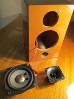
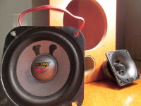
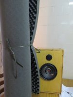
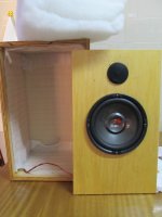
New pictures, right? Because this is fun, after all...
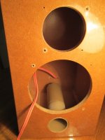
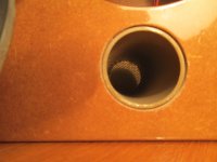
The box is 9.6 (h) x 6 (l) x 6 (d) inches. I made this box based on what WinISD Alpha and Beta told me to do. A vented 4.0 liter box. The port is 4cm wide (3,4cm) approx. 1 1/2 inches. Its length is 12cm or 4.78 inches.
You can also see my new foam.
I intend to put some on the small loudspeakers enclosure (this project).
Just to reiterate again, this is not a car project and has never been.
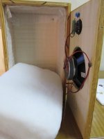
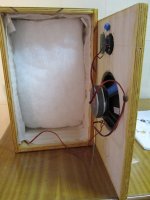
Other thread project: The old setup has gaskets with addition of polyester damping sheets. I confess, that at the time, I had no idea of what I was doing.
I also intend to replace the bigger loudspeakers damping material by the egg crate foam, perfectly cut.
PS. That 30 Liter enclosure is what I talk about on another thread.
The box is 9.6 (h) x 6 (l) x 6 (d) inches. I made this box based on what WinISD Alpha and Beta told me to do. A vented 4.0 liter box. The port is 4cm wide (3,4cm) approx. 1 1/2 inches. Its length is 12cm or 4.78 inches.
You can also see my new foam.
I intend to put some on the small loudspeakers enclosure (this project).
Just to reiterate again, this is not a car project and has never been.
Other thread project: The old setup has gaskets with addition of polyester damping sheets. I confess, that at the time, I had no idea of what I was doing.
I also intend to replace the bigger loudspeakers damping material by the egg crate foam, perfectly cut.
PS. That 30 Liter enclosure is what I talk about on another thread.
Attachments
Last edited:
Hi,
FWIW you just stuff a sealed box with fibreglass / rockwool / BAF /
pillow stuffing to suit, nice foam on the walls won't help much.
Vented boxes it will and it is the right sort of stuff. Though
the stuff you have is thicker than typical small box stuff.
rgds, sreten.
The tweeter datasheet sadly lacks an impedance curve,
so it is hard to predict the effect of a x/o on the given
driver response, which I assume is given driven directly.
I'm confused as hell, drivers intended for car use hardly
ever have suitable parameters at that size for 4L vented.
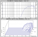
This is the effect of a typical box on a typical 6.5"/1", scale
the frequency upwards for a smaller typical driver and box :
FWIW you just stuff a sealed box with fibreglass / rockwool / BAF /
pillow stuffing to suit, nice foam on the walls won't help much.
Vented boxes it will and it is the right sort of stuff. Though
the stuff you have is thicker than typical small box stuff.
rgds, sreten.
The tweeter datasheet sadly lacks an impedance curve,
so it is hard to predict the effect of a x/o on the given
driver response, which I assume is given driven directly.
I'm confused as hell, drivers intended for car use hardly
ever have suitable parameters at that size for 4L vented.
This is the effect of a typical box on a typical 6.5"/1", scale
the frequency upwards for a smaller typical driver and box :
Last edited:
Hi,
FWIW you just stuff a sealed box with fibreglass / rockwool / BAF /
pillow stuffing to suit, nice foam on the walls won't help much.
Vented boxes it will and it is the right sort of stuff. Though
the stuff you have is thicker than typical small box stuff.
I am making the bigger box, vented.
In the other topic I was discussing this. Going vented.
So I will open a port on that. Won't use it sealed any longer.
Yes, it is a bit thicker for the small box.
Perhaps I will cut just some pieces like you said on another thread: doesn't need to be on all walls.
The tweeter datasheet sadly lacks an impedance curve,
so it is hard to predict the effect of a x/o on the given
driver response, which I assume is driven directly.
I will write the manufacturer technician asking for this.
I have looked into REW software, but I see that it requires some tools I don't have.
Perhaps this tech will send me a impedance graph.
These piezos are also used in a lot of PA systems.
I can help you a little with the small speaker here, krafty.
Bit like these Pure DMX-25 isn't it:
Coil on the bass (but add your Zobel if you want...), cap on the tweeter. Wired out of phase according to a little modelling I did.
Bit like these Pure DMX-25 isn't it:
An externally hosted image should be here but it was not working when we last tested it.
Coil on the bass (but add your Zobel if you want...), cap on the tweeter. Wired out of phase according to a little modelling I did.
An externally hosted image should be here but it was not working when we last tested it.
Good pics of your cabinets Krafty, and good job on getting more technical info on the LeSon tweeter! I think it is great that the Brazilian manufacturers are so responsive and helpful ! ....
That port in your cabinet for the smaller Hinor , how long is it? What frequency did you tune the box for using winISD?
That impedance graph that LeSon gave you isn't as flat as what that fellow measured in his video, surprising that they would be that much different since they are based on the same operating principle, same brand, similar range etc....
It also seems like they sent you the impedance response for the 8ohm version of that LeSon, if you will notice the impedance never goes below 6ohms on the graph ....... Nevertheless, its no big deal, just keep in mind that using parallel resistance will pull down the output of the LeSon in the range where the impedance peak is (centered between 7khz and 10khz) which can be a good thing if that range needs to be knocked down , on the other hand, if overused the small value resistors in parallel may cause a "suck out" between 7khz and 10khz so just be aware of that and use that adjustable option to your advantage
So it looks like between the careful choice of series cap, attenuation and parallel resistance you have quite a bit of control over your LeSon Piezo ...
Last edited:
Krafty, you had also mentioned earlier that you believed measurement microphones to be terribly expensive, and it is true that they can be, but they don't have to be .... You can buy these tiny electret microphone capsules made by Panasonic (model wm61a or wm61b) and solder up a cable to them and it can be plugged right into your soundcard... Your soundcard's microphone input will provide the small amount of voltage required to run the mic ..... You can usually find the Panasonic electret capsules for a couple of bucks a piece on the net .... I bought half a dozen of them a couple of years ago , and made a couple of measurement microphones out of them , the capsules fit handily into the end of a ballpoint pen shaft !! neat!
I took many useful and helpful measurements with my low cost Panny Pen microphones
I used TrueRTA as the software to generate sweeps & graphs but i am sure that the REW software you were looking at would also do the job
I took many useful and helpful measurements with my low cost Panny Pen microphones
I used TrueRTA as the software to generate sweeps & graphs but i am sure that the REW software you were looking at would also do the job
Last edited:
Hi Matthew,
Yes, they all replied me in like one day after I emailed them.
Hinor also sent me T/S parameters for all their drivers I have here.
That port is 12cm long. The frequency was 84 Hz.
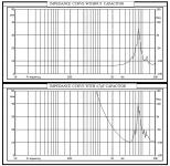
This impedance graph is really for the TLC-1. Both graphics were on a PDF. I just separated them and made them images. I don't think there is a 8 ohm version for TLC-1.
Let's see what sreten thinks about it...
Yes, they all replied me in like one day after I emailed them.
Hinor also sent me T/S parameters for all their drivers I have here.
That port is 12cm long. The frequency was 84 Hz.
This impedance graph is really for the TLC-1. Both graphics were on a PDF. I just separated them and made them images. I don't think there is a 8 ohm version for TLC-1.
Let's see what sreten thinks about it...
Here is the impedance curve of tweeter!!!!
Thanks to LeSon supplying this!
So, tell me sreten, WHAT NOW....
Hi,
Yes, well the plot thickens as the impedance curve is indeed
all over the place. However with the extremely high amount
of attenuation needed here just L-pad the tweeter with a
8 ohm series and low value parallel to negate the curve.
I have no idea what MMJ is talking about, regarding parallel
resistors, the smaller the parallel value the less peaking
you will get due to the series value and the impedance.
A small value cannot create a suckout, that is just wrong.
rgds, sreten.
Last edited:
I will explain, no problem,
First of all the impedance graph that they sent to him looks like an 8 ohm driver , not a 4ohm driver ..... Even without the series cap the impedance graph never dips below 6ohms, and with the series cap it never dips below 10 ohms within it's useful range, so once again if Krafty truly has 4 ohm driver in his possession then the graph we are looking at is not actually for Krafty's drivers ...
Krafty, what is the DCR of your LeSon drivers? Is it in the range 3 to 4 ohm? or 5 to 7 ohm range? If it is the latter range then that might be the proper graph, otherwise it is not and we are looking at a graph for another driver ...
Anyway, to explain myself when it comes to the parallel resistance/impedance response vs frequency response comments, its basically just a matter of relative attenuation meaning when there is a impedance rise and peak like what is shown in that graph (between 7-10khz) you can expect that when using parallel resistance (in parallel directly with the LeSon, in other words across the primary coil of his transformer) there will be attenuation of course, but the amount of attenuation will be greater where the impedance peak is located ..... So the response at 8khz will be attenuated much more than the responses at 5khz and 20khz (with parallel resistance that is)........
The reverse is also true when adding series resistance (would attenuate 5khz and 20khz more than 8khz .........
I was simply saying that this could be a useful phenomenon to exploit when trying to get his LeSon tweeter to sound acceptably good ..
The choices made in values and how to arrange the resistors could make the difference between a scooped response , or a response that has a big hump in the middle .... Or if we are good , a nice flat response
Last edited:
- Status
- This old topic is closed. If you want to reopen this topic, contact a moderator using the "Report Post" button.
- Home
- Loudspeakers
- Multi-Way
- Please check out my final circuit X/O with piezo