Yes Matthew, that could be the case with sreten.
One thing for sure is that I noticed that 8 inch woofers are crossed over at 2000-4000. And what I have is not a woofer really, it is a mid-bass. I don't know how that plays a part or if it should be considered as the same as a woofer. In woofers specs, I usally see usable range within 35-4000Hz. But the specs of this tiny 4 inch is between 117-8000, which is clearly not a conventional woofer.
But I still would like to have that coil sorted out, and why that tutorial has not considered the said phenomenon.
Woofer is more of a general term in my experience seems to be applied to anything from a 3 inch driver to a 21 inch (or more driver), covering all sorts of ranges, pretty generic .....
I think the term "midbass" or "midwoofer" is still used a little bit loosely but at least is more specific than "woofer" and in my experience seems to apply to drivers that are well suited to reproduce at least the 150hz - 400hz and often play well up into the upper midrange frequencies and beyond (into the treble) such as your little 4 inch Hinor .... Sometimes they extend lower as well ...
"Subwoofer" seems to be a little more specific, and is a good label for a driver that is best suited for the deeper bass range, generally have heavier cones & coils (moving mass) , lower resonant frequency (FS) and more xmax (linear cone travel)...
Im honestly not really sure if anyone has really bothered to establish any accepted exact standards or precise definitions and classifications blah blah blah and maybe its best to leave things a bit flexible ..
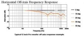
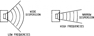
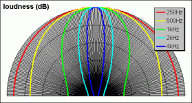
Krafty, there is a good reason that you will see a trend of larger diameter woofers using lower crossover points which is done for the purpose of avoiding problems like cone-breakup, and overly narrowed dispersion which is sometimes called "beaming" ...
Your 4 inch drivers should be ok for use up to 5khz or 6khz , the radiation pattern will start to be somewhat narrowed but should still be totally useable ..... With your 8inch drivers its a little bit of a different story, at 5khz an 8 inch woofer has much narrower dispersion which means it would sound ok as long as you are standing or sitting straight in front of the woofer (they call it "on axis" ) but if you walk around the room and move off to the sides of your speaker you will no longer hear those upper midrange & lower treble sounds, the upper mids will sound "scooped" and lack clarity until you walk back out in front of the speaker and then everything will sound good again.. ... It is only acceptable if your listening position is straight out in front of your speakers..
The above behaviour is a big problem for lots of commercially made 2-way pro audio cabinets made by big names that use a 15" woofer and a horn tweeter, im sure you have seen this type before, they are very common... With this design (unless their crossover point is set very low, which they are often not) there are major dispersion problems ... Its amazing that cabinets such as this example are so popular when their response falls completely apart if you are standing anywhere other than straight in front of it ...
This is one good reason why you shouldn't rely on your Hinor woofer to solely handle everything up to 10khz (which is what you would have been doing if you were to prevent your LeSon from reproducing sound below 10khz) ... So that would have been a bad idea ...
Its also the reason i will recommend going "3-way" for anyone who is wanting to build a speaker system based upon a 12 inch or 15 inch woofer...
Check out the different pictures that i attached, they are different ways to visualize the nature of dispersion.
Attachments
Last edited:
Matthew, I've seen that you've come up with a 4R resistor and a 4.7uF capacitor for the midbass impedance flattening job. As I read in the article, there are these values of Rdc and Le to take into account. How did you come up with 4R and 4.7uF ?
I have sent an email to Hinor asking for the midbass datasheet, specifically asking them for these two T/S parameters. So let's see what is their answer (if they ever answer).
(They did not go out of business - they just discontinued this product in question without leaving any legacy support or download).
I wanted to use values that you probably already had on hand (based on your earlier sketches and experiments), so this circuit was loosely based upon a "2nd order butterworth" filter at 6000-7000hz.. The values were "in the ballpark" enough to work ...
This will simply allow your coil to function more effectively and give you a sharper rolloff in the upper end response of your Hinor, in other words it should roll off faster above 6000hz with this circuit and that means there will be less overlap and less undesirable interaction with your LeSon ...
Take a look at the sketch , it explains how this method works ..
Attachments
If your LeSon still sounds "spitty" to you then i have some other methods to show you for actually treating the Piezo itself (adding a few simple things within the casing), dont worry, its easy and cheap ")
I built some Piezo arrays in the past using step up transformers and thats how i have some experience in this area ... After lots of measurements I found that i had to add some damping material around the piezo element itself (i used dryer lint! haha!) and i also ended up having to use a "swamping" resistor (200 to 300 ohm worked for me) across the secondary windings of the transformer (same as across the element's leads) to further flatten response, so as i said if your LeSon Piezo still sounds rough to you just let me know and i can show you how to modify it ..
When i finished with my Piezo arrays they sounded smooth and natural, much better than Piezos would normally ever sound ... For me it was definitely worth the extra effort ...
I built some Piezo arrays in the past using step up transformers and thats how i have some experience in this area ... After lots of measurements I found that i had to add some damping material around the piezo element itself (i used dryer lint! haha!) and i also ended up having to use a "swamping" resistor (200 to 300 ohm worked for me) across the secondary windings of the transformer (same as across the element's leads) to further flatten response, so as i said if your LeSon Piezo still sounds rough to you just let me know and i can show you how to modify it ..
When i finished with my Piezo arrays they sounded smooth and natural, much better than Piezos would normally ever sound
... For me it was definitely worth the extra effort ...
Last edited:
This was the network i ended up using for myself .....
I found that the final series resistor seemed more necessary when using only one or a few piezos, and if i was using a larger array that value could be reduced quite a bit .... Using a series value that was too high would result in attenuating the response above 10k too much , especially on larger arrays ..
The parallel "swamping" resistor made a very noticeable difference! It really flattened and smoothed the response at the cost of a few DBs worth of output..... That compromise was totally worth it ..
I find it interesting that i actually settled with a 2.2uf series cap (before the transformer) at 8 ohms, coincidentally thats the equivalent to 4.4uf at 4 ohms which is almost the exact same target crossover point that your LeSon requires ... I still got strong response right down to 3khz (with the GRS brand piezos, but the Goldwood 1016s would only go down to about 4 or 5khz )
by the way, my transformer secondary was around 300 ohms, the transformer i used was actually one designed for wideband "70v" distributed sound and was good up to 15khz +... .. So I re-purposed it
Attachments
Last edited:
Thanks a lot Matthew.
Well, you almost hit the nail on the resistor value for woofer. I did the math here. The "Rdc" or "Re" parameter of Hinor 4" is 3.51 Ohms. The ending resistor was about 4R3. So 4R was real close. I need to know what is the Le parameter, hopefully Hinor speaks this Tuesday about this.
Well, you almost hit the nail on the resistor value for woofer. I did the math here. The "Rdc" or "Re" parameter of Hinor 4" is 3.51 Ohms. The ending resistor was about 4R3. So 4R was real close. I need to know what is the Le parameter, hopefully Hinor speaks this Tuesday about this.

Updating the calculations...
Well, getting the value according the tutorial....
Re = 3,6 ohms -> 3,6 x 1.25 = 4,5 R (4R7) -> 4R7 ^ 2 = 22.09
Le = 0,345 mH (0.000345)
Now to establish the value for capacitor, following the same calculation principle...
0.000345 / 22.09 = 1.5617926663648709823449524671797e-5
0,000015617...
(according to the tutorial, 0.0004 divided by 46 is)
8.6956521739130434782608695652174e-6, which is:
0,000008695...
So if the tutorial is saying this value is 8.7uF, then the result of mine would be 15uF? Is that right?
An externally hosted image should be here but it was not working when we last tested it.
Good job on getting the complete specs from Hinor, that figure of .345mh is nice and low! thats a good thing! It means that only a small amount of capacitance is needed to compensate for the inductance in order the flatten the impedance curve ...
I will admit to be being somewhat terrible at math but if i count the placement in your figures i get 1.56uf for the first calculation and about 1.74uf for your second calculation and that seems like a very reasonable range....
It also looks like you used the wrong coil in the sketch, using a value any higher than 0.2mh would likely shift your filter point too low with the Hinor (would shift it to below 4.5khz) ....... 1.0mh shifts the crossover point to well below 700hz which would cause a gap in your response since your LeSon tweeter only plays down to around 5khz before it drops off pretty quickly below that...
Take a look at this quick reference guide that Parts Express makes available, it gives you an idea of the value ranges involved:
Resources - Crossover Component Selection Guide
Last edited:
Wondering why in that tutorial,
specifically THIS POST, he came up with 8.7uF
I confess that "not much of a filter" and "miles better" stuck in my head, as far as the coil is concerned. But others have stepped out of the thread and won't comment anymore. If 0.11 will do it, then it will be a win. The calculations so far gave me the exact 0.11mH, with the Hinor values and every cross over calculator out there, even with trying other "orders".
Last edited:
Hi,
The 1 mH coil on the 4 ohm bassmid is a ballpark number
for the rather tricky "baffle step compensation" of the driver.
Could be somewhat less.
http://audio.claub.net/Simple Loudspeaker Design ver2.pdf
FRD Consortium tools guide
http://web.archive.org/web/20090902124715/http://geocities.com/woove99/Spkrbldg/DesigningXO.htm
Ihave no idea if a zobel on the bassmid is needed or not, often
it isn't, and whether high pass will need a further capacitor.
The x/o is guesswork without knowing the impedance and
response of the piezo tweeter, online calculators don't help.
rgds, sreten.
http://sites.google.com/site/undefinition/diy
(see if nothing else, the excellent FAQs)
The Speaker Building Bible
Zaph|Audio
Zaph|Audio - ZA5 Speaker Designs with ZA14W08 woofer and Vifa DQ25SC16-04 tweeter
http://audio.claub.net/Simple Loudspeaker Design ver2.pdf
FRD Consortium tools guide
http://web.archive.org/web/20090902124715/http://geocities.com/woove99/Spkrbldg/DesigningXO.htm
RJB Audio Projects
http://web.archive.org/web/20090902202231/http://geocities.com/woove99/Spkrbldg/
Speaker Design Works
http://www.htguide.com/forum/showthread.php4?t=28655
Last edited:
Ok sreten, point taken.
When you say is "guesswork" I think you are saying that I must use some software, wire everything up and take the measurements right? You don't trust any of that datasheet which says the piezo is 4 ohms or the multimeter result I had, 4 ohms, or even the datasheet graph, is that right?
Matthew, well the maths really point to a 15,6 uF capacitor on the zobel network. I just used a online zobel calculator to confirm the previous manual calculation.
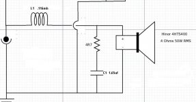
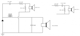
Updated the circuit, for now:
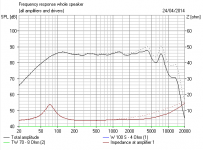
I will maintain the cross over split at 6000 Hz. I guess it was a good decision from the start. From the woofer's graph, 9000 is the max. 6000 is reasonable for cut.
I read about the Baffle Step thing, well... I don't know, as I read there are implications one can trap himself in, and for what I read, it is only necessary with some drivers? I think I won't go to the 1mH coil. Will stay with 0.11 with this set.
The piezo novel, well, I guess that the tutorial is not considering a piezo right? And a coil is not even needed like a normal cone tweeter... I may stick with either the two options I left in the circuit.
When you say is "guesswork" I think you are saying that I must use some software, wire everything up and take the measurements right? You don't trust any of that datasheet which says the piezo is 4 ohms or the multimeter result I had, 4 ohms, or even the datasheet graph, is that right?
Matthew, well the maths really point to a 15,6 uF capacitor on the zobel network. I just used a online zobel calculator to confirm the previous manual calculation.
Updated the circuit, for now:
I will maintain the cross over split at 6000 Hz. I guess it was a good decision from the start. From the woofer's graph, 9000 is the max. 6000 is reasonable for cut.
I read about the Baffle Step thing, well... I don't know, as I read there are implications one can trap himself in, and for what I read, it is only necessary with some drivers? I think I won't go to the 1mH coil. Will stay with 0.11 with this set.
The piezo novel, well, I guess that the tutorial is not considering a piezo right? And a coil is not even needed like a normal cone tweeter... I may stick with either the two options I left in the circuit.
An externally hosted image should be here but it was not working when we last tested it.
I haven't abandoned you krafty.
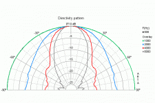
I'd be interested to see the frequency response of your 4" bass speaker.
You see it's obviously designed to run on the back shelf of a car, and sound reasonable with no filter at all.
The way to look at your bass filter is it just tilts down the top end a bit. The overall shape will be similar.
I just ran a 4" Visaton (Le 0.5mH) W100S-4 past boxsim as a wall mounter, which means it's close to a wall, so no bafflestep needed to boost the bass.
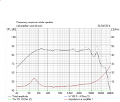
I think you can see what goes on with your filter of 0.11mH and 5R and 15uf, and a secondly with a slightly bigger 0.22mH coil plus half Zobel of 5R and 6.8uF. The dotted line is running fullrange, i.e. no filter.
This looks like it might work to me.
I'd be interested to see the frequency response of your 4" bass speaker.
You see it's obviously designed to run on the back shelf of a car, and sound reasonable with no filter at all.
The way to look at your bass filter is it just tilts down the top end a bit. The overall shape will be similar.
I just ran a 4" Visaton (Le 0.5mH) W100S-4 past boxsim as a wall mounter, which means it's close to a wall, so no bafflestep needed to boost the bass.
I think you can see what goes on with your filter of 0.11mH and 5R and 15uf, and a secondly with a slightly bigger 0.22mH coil plus half Zobel of 5R and 6.8uF. The dotted line is running fullrange, i.e. no filter.
This looks like it might work to me.
Attachments
Krafty ,
Sreten is absolutely right to suggest BSC if you were to put those speakers up on stands in a room and there wasn't much "boundary loading" to speak of however since we are talking about the rear deck of a car System7 makes an extremely good point, because if your speakers will be sitting on the rear deck of a car with a window above it (assuming its not a convertible) there will be a loading of the Hinor at lower frequencies giving you a nice boost which would eliminate any need for baffle step correction. Other great (non auto) alternatives for placement would be in a corner or even better yet where the corner and ceiling meet (in a room) giving you even more boundary loading ..
Sreten, good list of links you posted, a few are broken but still lots of good stuff in there! The FRD stuff & speaker workshop look pretty interesting, and i have been thinking about trying something like the Wallin Jig since the wt3 or DATS are unavailable right now ...
What I wanted to check is for a proprietary or free software application that will give me measurements. I looked into the SpeakerWorkshop that is said to just do that - but when I started to read the tutorial, I have to previously have had the driver files. Also there is nothing on the website explaining how to measure the driver.
Thanks system7, yes, that speaker is a car speaker designed to maybe operate without any filter, but for fun, I will do that. This is going to be my fun crossover. Just don't want it too slack or done in a sloppy way. Learned a lots with it, and keep learning. Some of the things are really picky (like this BSC thing). Anyway, I will not put this 4 inch in a car, no way. That picture where it is already placed on the enclosure is its final home... My second SERIOUS cross-over, oh I may even buy real software to get the guns loaded....
Thanks system7, yes, that speaker is a car speaker designed to maybe operate without any filter, but for fun, I will do that. This is going to be my fun crossover. Just don't want it too slack or done in a sloppy way. Learned a lots with it, and keep learning. Some of the things are really picky (like this BSC thing). Anyway, I will not put this 4 inch in a car, no way. That picture where it is already placed on the enclosure is its final home...
My second SERIOUS cross-over, oh I may even buy real software to get the guns loaded....I remember when this discussion started one of the big issues was the low efficiency rating of the woofer versus the high efficiency of the tweeter, and the need to pad the tweeter to match the output of the woofer ...
It seemed to me that the last thing you would want to do in this situation is to knock down the upper midrange efficiency of an already very inefficient woofer when it has to integrate with a very loud piezo that comes in with a very abrupt curve just above 4khz .... That was my logic when suggesting a simple & low-loss crossover on his woofer, or even no crossover at all (running it dry) ... This really is something to consider especially when the low power output of Krafty's amp would mean that headroom is already limited ... It seems that the LeSon tweeter would already have to be attenuated by more than 15 decibels to integrate properly, so why exacerbate the situation? ( meaning lower efficiency & output from the woofer results in having to attenuate the tweeter even more! which is a bad thing especially when you dont have very much amplifier power to work with)
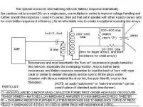
Looking at the numbers that Krafty posted earlier i realize that I wasn't counting the decimal placement properly, so it is 15uf after all according to Krafty's figure, so my mistake, but i think i was biased because even 15uf of parallel capacitance seemed like too much for what we were trying to accomplish here, after all Krafty's Hinor driver has a very low LE figure ... I wanted to verify so I tinkered around with the simple Zobel calculator here Crossover Calculators : Custom Car Stereo - Complete Car Audio Building Guide and i am seeing that it recommends an even higher capacitor value of around 25uf in order to compensate for only .33mh .... 25uf ! EGAD! This seems like a bad idea if trying to maintain full efficiency of the driver, and i will explain my reasoning :
A 25uf capacitor used in a zobel will begin to direct power into the resistor to be absorbed as early as 1000hz and thats more than two octaves below our target crossover frequency of 5khz to 6khz , making this configuration lossy in the upper midrange which would worsen the discrepancy between the woofer's output at 5khz and the LeSon tweeter's output ...... Alleviating that discrepancy was the whole purpose of starting this discussion in the first place right? We certainly don't want to make it worse.
So i want to propose an alternative which i think would be superior because it is less lossy than using the zobel concept and would provide a sharper cutoff at the desired crossover point to reduce unwanted interactions between the drivers (12db per octave versus 6db per octave) .... Take a look at the sketch, the series coil and parallel cap form a second order Butterworth 12db per octave low pass at 6000hz .. Could be worth simulating whaddya think System7? The recommended choke value is .15mh though it seems that using the .11mh choke would drive the Q of the filter up a little ..
It seemed to me that the last thing you would want to do in this situation is to knock down the upper midrange efficiency of an already very inefficient woofer when it has to integrate with a very loud piezo that comes in with a very abrupt curve just above 4khz .... That was my logic when suggesting a simple & low-loss crossover on his woofer, or even no crossover at all (running it dry) ... This really is something to consider especially when the low power output of Krafty's amp would mean that headroom is already limited ... It seems that the LeSon tweeter would already have to be attenuated by more than 15 decibels to integrate properly, so why exacerbate the situation? ( meaning lower efficiency & output from the woofer results in having to attenuate the tweeter even more! which is a bad thing especially when you dont have very much amplifier power to work with)
Looking at the numbers that Krafty posted earlier i realize that I wasn't counting the decimal placement properly, so it is 15uf after all according to Krafty's figure, so my mistake, but i think i was biased because even 15uf of parallel capacitance seemed like too much for what we were trying to accomplish here, after all Krafty's Hinor driver has a very low LE figure ... I wanted to verify so I tinkered around with the simple Zobel calculator here Crossover Calculators : Custom Car Stereo - Complete Car Audio Building Guide and i am seeing that it recommends an even higher capacitor value of around 25uf in order to compensate for only .33mh .... 25uf ! EGAD! This seems like a bad idea if trying to maintain full efficiency of the driver, and i will explain my reasoning :
A 25uf capacitor used in a zobel will begin to direct power into the resistor to be absorbed as early as 1000hz and thats more than two octaves below our target crossover frequency of 5khz to 6khz , making this configuration lossy in the upper midrange which would worsen the discrepancy between the woofer's output at 5khz and the LeSon tweeter's output ...... Alleviating that discrepancy was the whole purpose of starting this discussion in the first place right? We certainly don't want to make it worse.
So i want to propose an alternative which i think would be superior because it is less lossy than using the zobel concept and would provide a sharper cutoff at the desired crossover point to reduce unwanted interactions between the drivers (12db per octave versus 6db per octave) .... Take a look at the sketch, the series coil and parallel cap form a second order Butterworth 12db per octave low pass at 6000hz .. Could be worth simulating whaddya think System7? The recommended choke value is .15mh though it seems that using the .11mh choke would drive the Q of the filter up a little ..
Attachments
Last edited:
When sreten gives you the 14 links treatment, krafty, he thinks you're a pretty hopeless case...
But stick to your guns here. You're doing OK.
Now back on-topic. Matthew, you can't just put a 4.7uF capacitor after a coil that is smaller than the speaker Le. It just produces a horrible peak at the top, because the voicecoil inductance reduces the LC damping. You can do that with some added shunt resistance, but you actually end up with something that doesn't do much.
Bafflestep bass boost is actually quite a modern invention. In the old days people just put speakers in a big box near a wall. It does much the same and is much more efficient because the bass coil is smaller.
I'm not suggesting these speakers can only go in a car. But they need to go near a boundary for sure if you want some bottom end.
Your simplest filters are something like a 0.3mH coil all on its own, or the two filters I modelled. They all do much the same, which is really just a slope adjustment and rolloff at around 6kHz. It's so rough and ready, that your ears will be your best guide. That and looking at the manufacturer's frequency response and knowing what you can do to it. I don't mind Zobels. They sound nice.
- Status
- This old topic is closed. If you want to reopen this topic, contact a moderator using the "Report Post" button.
- Home
- Loudspeakers
- Multi-Way
- Please check out my final circuit X/O with piezo