Ok, the woofer gets really weak after 5000 Hz to 7000 Hz.
The tweeter, this time with the 4.7uF cap, starts at 900. But its intensity and power really picks up from where the woofer left at 5000 and on.
I guess now he know what value for the air core filter, and tweaks to the circuit?
The tweeter, this time with the 4.7uF cap, starts at 900. But its intensity and power really picks up from where the woofer left at 5000 and on.
I guess now he know what value for the air core filter, and tweaks to the circuit?
Krafty , This is great news
What you want is the woofer to drop off right around where the tweeter picks up and it sounds like you have figured out that you have almost exactly that")
5khz to 6khz can be considered your crossover point and since your woofer has a natural rolloff right around where you want it to be I wouldn't worry about using any extra components on your woofer right now, you can run it without a coil and the woofer itself will actually be most efficient that way because there are no losses due to series coils or extra components ....The only thing i would worry about is adjusting the cap and resistor on your tweeter circuit to get it to start playing strongly around 6khz or so, a slightly smaller value cap should achieve this (perhaps 4.2uf).
The goal of course is to get a smooth transition from the woofer to the tweeter, so when you get it dialed in perfectly you can have both your tweeter and woofer hooked up to your amp and play a sweep from 1khz to 10khz and hear a nice steady volume level with no noticeable big peaks or dips throughout the sweep ..
When using a simple filter like we are talking about there is always going to be a small amount of overlap, which is to be expected .... If it turns out that there is some interference in the overlap region (sounds like peaks and dips in the 4khz-8khz range) then you can try flipping the phase on one of the drivers, sometimes that fixes it, and if not we can devise a "2nd order" crossover (a coil & cap for each driver) which will give you a sharper filter slope but lets try to make the simplest solutions work first ...
What you want is the woofer to drop off right around where the tweeter picks up and it sounds like you have figured out that you have almost exactly that
5khz to 6khz can be considered your crossover point and since your woofer has a natural rolloff right around where you want it to be I wouldn't worry about using any extra components on your woofer right now, you can run it without a coil and the woofer itself will actually be most efficient that way because there are no losses due to series coils or extra components ....The only thing i would worry about is adjusting the cap and resistor on your tweeter circuit to get it to start playing strongly around 6khz or so, a slightly smaller value cap should achieve this (perhaps 4.2uf).
The goal of course is to get a smooth transition from the woofer to the tweeter, so when you get it dialed in perfectly you can have both your tweeter and woofer hooked up to your amp and play a sweep from 1khz to 10khz and hear a nice steady volume level with no noticeable big peaks or dips throughout the sweep ..
When using a simple filter like we are talking about there is always going to be a small amount of overlap, which is to be expected .... If it turns out that there is some interference in the overlap region (sounds like peaks and dips in the 4khz-8khz range) then you can try flipping the phase on one of the drivers, sometimes that fixes it, and if not we can devise a "2nd order" crossover (a coil & cap for each driver) which will give you a sharper filter slope but lets try to make the simplest solutions work first ...
I think it will be alright, because the woofer can really extend its treble to the point of sounding like the tweeter around 6kHz.
How do I calculate the new values using a 4.2uF load
4 ohms ( LeSon Tweeter = 4ohm load ) : 4.7uf
Rounded equivalencies are listed below:
14 ohms (10 ohm series resistor + 4 ohm load) : 1.3uf
19 ohms (15 ohm series resistor + 4 ohm load) : 1uf
26 ohms (22 ohm series resistor + 4 ohm load) : 0.7uf
31 ohms (27 ohm series resistor + 4 ohm load) : 0.6uf
37 ohms (33 ohm series resistor + 4 ohm load) : 0.5uf
How do I calculate the new values using a 4.2uF load
Last edited:
... the series coil on the woofer might not be needed, but if it is needed
a value of .11mh (around one tenth of a millihenry) is appropriate, ....
Hi,
Which shows you know next to nothing about real x/o design.
1mH is miles better, and if you don't know why don't pontificate.
rgds, sreten.
Last edited:
Ok Krafty ,
I will draw you up another equivalency list , it will be based upon 4.2uf instead of 4.7uf , which gives us a virtual target of around 9400hz versus 8400hz , and with the transformer driven piezos lower range response "tilt" you should get strong output from the tweet starting at around 6khz as opposed to 5khz..
I will draw you up another equivalency list , it will be based upon 4.2uf instead of 4.7uf , which gives us a virtual target of around 9400hz versus 8400hz , and with the transformer driven piezos lower range response "tilt" you should get strong output from the tweet starting at around 6khz as opposed to 5khz..
Sreten,
MILES better ? Why not kilometers? you are in the UK aren't you? ... hehe .. sorry , bad joke ..
You have a strong opinion about the 1mh choke so i have to admit that i am curious to hear you expound upon your viewpoint ....
You do realize that Krafty is working with a 4ohm driver right?
When i use a simple crossover calculator to determine the crossover point of a 4ohm driver with a single series 1mh coil i get a result of 600hz high pass with 6db per octave slope, and that crossover point would of course be way too low for Krafty's purposes.....
I am fully aware that the impedance response of almost any moving-coil/magnet based driver is a rising sort of response based upon the LE (inductance) of a driver, (roughly this trend is the inverse of a raw piezo with no step-up circuit) ... In other words , to your amplifier a magnet/voicecoil motor based driver looks (with the exception of "Z" at "FS") like a parallel coil and a raw piezo looks like a parallel capacitor ...
So its true that Krafty's 4 inch driver may not be EXACTLY 4ohms at 5000hz , it will surely be slightly more than 4 ohms at that frequency but not so high as to call for a tenfold discrepancy in the value of the choke used..... That seems a bit much doesn't it?
Anyway, if Krafty is really concerned about completely eliminating the woofers 7000khz+ output then he can just use the .11mh series chokes that he had made and then place one of his 4.7uf poly caps in parallel (can be put across the terminals of the woofer to make it an easy test), this arrangement will make the effects of the woofer's rising impedance response a non-issue and give him a sharper low-pass filter curve (with a "Q" slightly higher than a 2nd order Butterworth) which will probably be more steep than he really even needs considering the natural rolloff of his woofer ....
Nevertheless Sreten i'm always trying to keep an open mind and i love to learn new things so if you have some constructive input please enlighten me or let me know where my logic is flawed or where my calculations may have gone awry ..
MILES better ? Why not kilometers? you are in the UK aren't you?
... hehe .. sorry , bad joke .. You have a strong opinion about the 1mh choke so i have to admit that i am curious to hear you expound upon your viewpoint ....
You do realize that Krafty is working with a 4ohm driver right?
When i use a simple crossover calculator to determine the crossover point of a 4ohm driver with a single series 1mh coil i get a result of 600hz high pass with 6db per octave slope, and that crossover point would of course be way too low for Krafty's purposes.....
I am fully aware that the impedance response of almost any moving-coil/magnet based driver is a rising sort of response based upon the LE (inductance) of a driver, (roughly this trend is the inverse of a raw piezo with no step-up circuit) ... In other words , to your amplifier a magnet/voicecoil motor based driver looks (with the exception of "Z" at "FS") like a parallel coil and a raw piezo looks like a parallel capacitor ...
So its true that Krafty's 4 inch driver may not be EXACTLY 4ohms at 5000hz , it will surely be slightly more than 4 ohms at that frequency but not so high as to call for a tenfold discrepancy in the value of the choke used..... That seems a bit much doesn't it?
Anyway, if Krafty is really concerned about completely eliminating the woofers 7000khz+ output then he can just use the .11mh series chokes that he had made and then place one of his 4.7uf poly caps in parallel (can be put across the terminals of the woofer to make it an easy test), this arrangement will make the effects of the woofer's rising impedance response a non-issue and give him a sharper low-pass filter curve (with a "Q" slightly higher than a 2nd order Butterworth) which will probably be more steep than he really even needs considering the natural rolloff of his woofer ....
Nevertheless Sreten i'm always trying to keep an open mind and i love to learn new things so if you have some constructive input please enlighten me or let me know where my logic is flawed or where my calculations may have gone awry ..
Last edited:
Krafty , you can calculate the crossover cap equivalents using any simple crossover calculator, there should be one built into your winISD software ...
I made a new list for you based on the series 4.2uf as the reference
("1st order" 9400hz at 4ohm)
same format
4 ohms ( LeSon Tweeter = 4ohm load ) : 4.2uf
Rounded equivalencies are listed below:
14 ohms (10 ohm series resistor + 4 ohm load) : 1.2uf
19 ohms (15 ohm series resistor + 4 ohm load) : .9uf
26 ohms (22 ohm series resistor + 4 ohm load) : 0.65uf
31 ohms (27 ohm series resistor + 4 ohm load) : 0.55uf
37 ohms (33 ohm series resistor + 4 ohm load) : 0.45uf
So in other words as one option you would arrange the components in the order of:
amp--> 0.65uf capacitor---->22 ohm resistor--->LeSon
Last edited:
So, back again...
Tested the last incarnation of the circuit, with the shunt and 0.11mH filter. I can tell you that the tweeter is very muffled. If I short-wire the 22R, there is no effect. If I place another 4.7uF cap making 5.36uF, there is a tiny improvement in treble. But I guess this would be "alright" for a standard golden ear. My ears are kinda not so golden and demand a bit more treble.
Seems like the 4.7uF + 11R in the living room enclosure is much better.
Krafty ,
The shunt resistor is attenuating the signal a bit .... No problem , you will just have to use an option in our list which has a smaller value series resistor ... I would try the first option in the list which employs the 10ohm resistor and the 1.2uf cap (except that if you include the shunt resistor it makes the tweet look like a 2ohm load so that series cap should really be 1.4uf)
I could draw up a sketch for you if you like .....
Or you could just try removing the shunt resistor, making it similar to the network in your living room speakers ....
Let us know how it goes
Ok, here's my latest findings...
The coil seems to be "null" on this circuit. If I shortwire it, no changes.
I am rectifying some of the things in this test...
First my amp had treble and bass on +10db level, for playing music. I think I am not supposed to find the right spot with these settings this way. So I brought everything to 0dB on the hardware amp. If I do this, trying to find the right spot with no hardware or software EQs, then I come to the conclusion 22 Ohms is too much for attenuation. (Or am I really supposed to find the spot on my current EQ settings?)
The only test I was doing right, with all leveled at 0dB was the signal generator.
Update:
Ok, now I tested:
1.5uF + 11 Ohms (with shunt) - sounds nice if the treble is +10db on hardware amp, muffled on 0dB hardware amp.
(to me it sounded also equivalent to having the resistor before 5R6 and a 4.7uF cap without shunt)
1.5 + 11 Ohms (without shunt) - too bright on +10dB and "ok" on 0dB.
Last edited:
I am starting to think that this tweeter needs to be crossed over at 10.000Hz. It spits a harsh sound within the range 6000-9500. Very smooth butter sound above 10k.
But then I need to be careful to not leave the midbass without mediums. I think a 1mH coild would just do that? I will need the mediums if I cross the tweeter this high.
But then I need to be careful to not leave the midbass without mediums. I think a 1mH coild would just do that? I will need the mediums if I cross the tweeter this high.
You are correct about needing to do all tests with the EQ settings at 0 ... That way you know that the frequency response of the amp is close enough to "flat" for the sake of accuracy..
If all goes well we can get your speaker to sound reasonably good without EQ, and right now at this stage that is the goal we should be striving for ..
In the end, if we have done a good job of choosing the right values for your network then only minimal amounts of EQ will be needed for satisfying sound when you are listening to music (at least when it comes to midrange and treble, but better bass would require modifying the cabinet)
Last edited:
So Krafty, it sounds like you found out that you need around 10 ohms of series resistance (without the 4ohm shunt) or a 5ohm series resistor along with the shunt which actually calls for the cap to be 2.5uf ....
Both of those above options will sound exactly the same with your tweet since it's impedance is likely well behaved (like the LeSon in the youtube video which uses the same internal step-up circuit) ...
If you want to reduce the amount of 5000-9000hz spittiness that you are hearing you might want to try a cap with a slightly lower value such as 1.2uf instead of 1.5uf (or 2.2uf instead of 2.5uf) , and just let me know if that gives you a sound quality that is closer to what you prefer to hear, ok? then we know which direction to take things.
About your woof, your coil will only lower the 6000hz+ frequencies and it's effects might be subtle in that lower range, there is a simple way to increase it's effectiveness though(with components that you already have), and we can do that if it is necessary to reduce the interaction between your LeSon and woofer (in the range where they overlap a bit ) to smooth things out ...
I can sketch up a schematic for you if you want to see how this is done ..
Last edited:
So Krafty, it sounds like you found out that you need around 10 ohms of series resistance (without the 4ohm shunt) or a 5ohm series resistor along with the shunt which actually calls for the cap to be 2.5uf ....
Both of those above options will sound exactly the same with your tweet since it's impedance is likely well behaved (like the LeSon in the youtube video which uses the same internal step-up circuit) ...
Yes, the thing is... 1.2 is hard, I will need to buy more caps
If you want to reduce the amount of 5000-9000hz spittiness that you are hearing you might want to try a cap with a slightly lower value such as 1.2uf instead of 1.5uf (or 2.2uf instead of 2.5uf) , and just let me know if that gives you a sound quality that is closer to what you prefer to hear, ok? then we know which direction to take things.
I usually test with songs:
Depeche Mode - World In My Eyes
Kraftwerk - Music Non Stop (The Mix Version)
These have sharp percussion and pristine cymbals so that is where I follow. Lots of synth based bands. I do notice that it can get a bit muffled with guitar bands though.
About your woof, your coil will only lower the 6000hz+ frequencies and it's effects might be subtle in that lower range, there is a simple way to increase it's effectiveness though(with components that you already have), and we can do that if it is necessary to reduce the interaction between your LeSon and woofer (in the range where they overlap a bit ) to smooth things out ...
I can sketch up a schematic for you if you want to see how this is done ..
Yeah, I kinda noticed that it has a very subtle effect. Was testing here without the tweeter connected. However, folks saying I need 1mH, it would get even less mediums, is that right? I might buy those just to see what gives... Know of a cheap online store to get those 1mH?
Yeah, you can sketch this up, please.
Also interested on what sreten has to say as rebuking whatever that he thinks it's wrong, preferably not with replies in bits.
I took the late night to read this post.
So, I am going to start over and try to follow everything that is in there. Including adding components to the midbass.
I feel relieved that the air core filter, 0.11mH looks like the ideal according to the calculations of that tutorial. A 4 ohm midbass on a crossover point of 6.000Hz would be: 4 / (6.3 * 6000) = 4 / 37800 = 0.000105 = 0.11mH aprox.
But there is still impedance correction to be made, something I didn't do.
So that is why I am asking others here why they said this is not much of a filter, but instead 1mH is...
I realize I have been speaking crap on some posts and paying as an imbecile, even knowing the pretty basics of electronics. A cross over cut at 10.000Hz? That was laughable. Anyway! I will try to get more serious. You know, in the beginning you start as a total amateur, but then after defeating your laziness of reading, things start to make sense. A lot of you have contributed to a large extent, even through disagreements, it only helped me to move forward on this. Now I am planning on 2 projects, and it started as a very naive first project back in 2012.
Anyways I will seat down here and recalculate the whole scheme. Seems like the tweeter will still be the major villain being a piezo, but to be honest I am not seeing much of a difference of crossing it over from that tutorial, apart from a shunt cap and resistor and an additional inductor. Wellll... we'll see. I am even willing to buy conventional small tweeters if I find them here. I have to confess that the whole piezo thing wore me out. But I don't plan trashing them any soon, so I will try to work this out in the new scheme. But if I can get conventional tweeters, or cone tweeters this small, to fit in the same place, I'd be glad acquiring them.
Since I am also going to replace the living room drivers and no piezo tweeters in there, looks like I will be trashing all 4 piezos in the future
Any of you know a place to buy good price inductors on the internet (USA, Canada or UK)? (Except Parts-Express). Looks like I will need more.
I will keep you updated.
Last edited:
RIGHT ON !
Songs by Kraftwerk and Depeche mode often find themselves in our eclectic playlist here at our house good stuff
I'm glad you are not giving up on your project here, it can be a fun learning experience when it is not so frustrating but overcoming the challenge is so very rewarding when you finally do get things sorted out and declare victory!
Piezos are notoriously difficult to work with and some honestly do sound literally like "scraping nails on a chalkboard", but your LeSon is not so bad really, its actually better than many of the piezos out there, and it sounds like you are making progress and getting closer to your desired sound
Songs by Kraftwerk and Depeche mode often find themselves in our eclectic playlist here at our house
good stuff I'm glad you are not giving up on your project here, it can be a fun learning experience when it is not so frustrating
but overcoming the challenge is so very rewarding when you finally do get things sorted out and declare victory!Piezos are notoriously difficult to work with and some honestly do sound literally like "scraping nails on a chalkboard", but your LeSon is not so bad really, its actually better than many of the piezos out there, and it sounds like you are making progress and getting closer to your desired sound
Krafty,
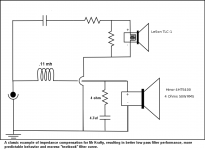
I am glad that you are starting to consider the subject of impedance compensation because it is what i was going to include into the next sketch for you, a method to allow your .11mh coils to have a moreso "textbook" and reliable filtering effect.
As far as inductors (coils) for woofers are concerned i do understand where Sreten was (probably) coming from with his suggestion of a higher mh value, and it is due to the fact that any woofer's voicecoil (being a coil) has an inductance (mh) value of it's own which can take away from the effectiveness of a series coil via the rising impedance response (feature of inductance) of the voicecoil, so some people will just use a larger value series coil to compensate for this phenomenon, but being that your woofer has a small voicecoil, and is usable up to 8000hz would all indicate that your woofer's inherent inductance is likely to be rather small. So the amount of compensation needed will also be rather small (not tenfold) ... ANYWAY, there are other simple ways to compensate for the voicecoil's inductance ... I will demonstrate with the following sketch using parts that you already have :
Attachments
- Status
- This old topic is closed. If you want to reopen this topic, contact a moderator using the "Report Post" button.
- Home
- Loudspeakers
- Multi-Way
- Please check out my final circuit X/O with piezo