Krafty,
Im sure there is an easy way to calculate the resistor value that you need , 22 ohms will be too low im sure, you might want to try a 33ohm and if the tweeter is still to loud compared to your bass/midrange driver then try a 47ohm and if that is too quiet then you know you need something between 33 and 47...
The best way to do it would be to try these different values while playing some familiar music through your woofer as you connect these different values of resistors, when you get close to the right resistor value you should have a pleasant and balanced sound =)
Last edited:
Matthew, I believe the tweeter is permanently damaged. No issues. I will get another one on monday, for something like 5 USD. I would never do that if the price was higher. I am like this, sometimes taking things to the extreme.
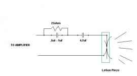
I have already tested a 1.5uF + 22 Ohm resistor + 0.47uF all in serie and didn't like that much, I found a bit muffled to my taste.
My next test is: 4.7uF + 22R + 0.15uF. Don't know if that makes much sense. Advise?
If this has to be in series, that resistor may want to go down a bit, so it releases more treble. I think the point here is not even being "loud" or "match" the bass driver. I think it should be the intensity of treble, right? The right pleasant point of treble that I should be looking for... Learning a lot of things with this, believe me. I know folks already told me to satisfy my ears but also I don't want to ignore specific techs in doing this.
Krafty, Using the three components in series like you described above will probably shift the crossover point extremely high which can create a big hole in your response between the upper range of your woofer and the output of the tweeter, keep in mind that the two responses have to meet in the middle to properly reproduce the full spectrum of music ....
From your posts i think i am getting an idea of what you are trying to achieve, and there is a way that you can attenuate the level while making the tweeter sound more "airy" and sweet to the ears (less "muffled" as you say) without creating a hole or gap in your response, take a look at the schematic i drew for you ..")
From your posts i think i am getting an idea of what you are trying to achieve, and there is a way that you can attenuate the level while making the tweeter sound more "airy" and sweet to the ears (less "muffled" as you say) without creating a hole or gap in your response, take a look at the schematic i drew for you ..
Attachments
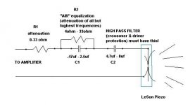
Krafty, here yah go, i added some more details and ranges of values to the Sketch , and also a little explanation ...
You will have to determine whether or not you prefer to hear more of the tweeter's upper range (10khz-20khz) or if you are needing to hear more of the lower range (4khz-10khz) ...
"AIR" is a term used to describe the upper range of your tweeter and when it is lacking music will tend to sound dull, lifeless or low fidelity .... Many poorly adjusted PA systems can lack "air" and instead have far too much of the lower treble range creating a sound described as "harsh", "brassy", or "shrill", "ear piercing" and is generally just not at all pleasant to listen to .... On the other hand not having enough of this low treble range can be equally as bad causing the vocals to lose their clarity and certain instruments lose their bite & definition or tend to get lost in the mix ...
Your job is to adjust the values of these components (R2, C1, C2) to give yourself the proper balance of upper and lower treble sounds and then in the end adjust R1 to attenuate the output of the tweeter enough to match the level of your woofer so that your tweeter and woofer compliment each other properly and reproduce music accurately.
A quick rundown of what these components do specifically:
R1= just plain old attenuation, reduces all sounds from your LeSon equally, higher values will attenuate more (adjust this resistor last to match the LeSon to your woofer)
C2= Defines your main high-pass filter's cutoff frequency, in other words it sets the low end cutoff for your LeSon and protects it from lower frequencies preventing damage much like a series cap would protect any standard magnet-&-moving-coil based tweeter or compression driver.... If it seems like you don't have enough of the lowest treble sounds in your LeSon's range (around 4khz) then you can increase C2's value, and if it sounds like there is too much lower treble then you can decrease C2's value, keep in mind though that unless your woofer is capable of putting out sound above 4khz reliably i would not lower this value from the recommended 4.7uf value or you can risk creating a big hole in your response, and you wouldn't want to have any missing notes in that very vital range..
R2 & C1= These components are piggybacked (paralleled with one another) and placed in series with the circuit .... Its pretty simple, R2 attenuates the signal but ONLY below a frequency determined by C1 and above that frequency there is no attenuation, so you can can use this to give yourself a rise in response at the very high end of the LeSon's range .. For example using an C1 value of 2uf and an R2 value of 10 ohms should attenuate output below 10khz and give you a noticeable rising response above 10khz resulting in a moreso "airy" and sparkling sound ... Increasing the value of R2 will exaggerate the effect ... Changing the value of C1 to a lower value like 1.5uf will shift the filter's crossover point higher to something closer to around 15khz depending a bit on the exact impedance of your LeSon .....
So do lots of listening tests and adjust these components until you are satisfied with the results! Happy tinkering and good luck my friend!
Attachments
Hi,
A capacitor in series with a piezo acts as an attenuator,
Series resistors affect high FR but simply don't attenuate.
Quite frankly there is a a load of utter nonsense
in this thread regarding proper general piezo use.
rgds, sreten.
There used to be a really good guide for piezos on this
site, in the Wiki section, but I can't find it anymore.
Last edited:
Hi again sreten...
Are you talking about THIS article?
diyAudio.com Wiki - projects by fanatics, for fanatics
This is the same as the Frugal-Phile article, word by word.
And it reinforces the paralell wiring of the resistor.
Are you talking about THIS article?
diyAudio.com Wiki - projects by fanatics, for fanatics
This is the same as the Frugal-Phile article, word by word.
And it reinforces the paralell wiring of the resistor.
Sreten,
The piezo Krafty is using is not a standard piezo, the fact that it includes an internal transformer or autoformer makes it a very different animal .... LeSon's internal autoformer acts as an impedance interface designed to match the very high impedance of the piezo element to a low impedance amplifier.
The matching network or crossover design that should be with a LeSon style piezo is different than what you would use with other piezos ... The LeSon actually presents a load that is much more akin to a standard magnet/moving-coil style tweeter.
Sreten,
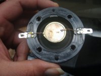
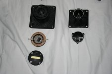
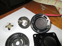
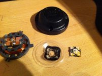
To give you some examples of what i am talking about take a look at these pictures, they are your common piezo tweeters.. Notice that they have no coil or transformers whatsoever. Most piezo tweeters are built this way just like the old CTS/Motorola classics and most of the copies of the Motorolas that Goldwood, GRS and even Pyle makes, such as the model 1016s and the model 1025s , and the model 1005s.. These are all based off of the old Motorola designs which did not have internal step-up transformers or autoformers built into them.... Being that this type of piezo design has always been the type that is most commonly found means that most of the suggested information about piezo tweeter networks that you can discover out there on the internet is based on Piezo tweeters without any internal impedance matching autoformers or transformers.. They are very high impedance devices, with an impedance that changes with frequency, generally dropping in impedance (like a capacitor) as you go up in frequency except for a little dip at their resonant frequency AKA "turn on" frequency ..
To give you some examples of what i am talking about take a look at these pictures, they are your common piezo tweeters.. Notice that they have no coil or transformers whatsoever. Most piezo tweeters are built this way just like the old CTS/Motorola classics and most of the copies of the Motorolas that Goldwood, GRS and even Pyle makes, such as the model 1016s and the model 1025s , and the model 1005s.. These are all based off of the old Motorola designs which did not have internal step-up transformers or autoformers built into them.... Being that this type of piezo design has always been the type that is most commonly found means that most of the suggested information about piezo tweeter networks that you can discover out there on the internet is based on Piezo tweeters without any internal impedance matching autoformers or transformers.. They are very high impedance devices, with an impedance that changes with frequency, generally dropping in impedance (like a capacitor) as you go up in frequency except for a little dip at their resonant frequency AKA "turn on" frequency ..
Attachments
Last edited:
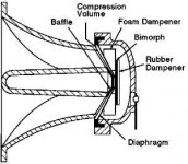
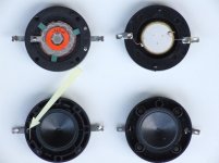
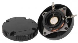
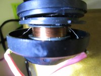
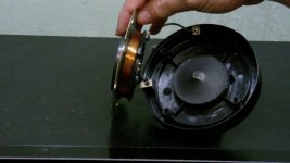
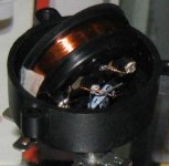
Here are some examples of the OTHER type, The LeSon style of design with the internal step-up transformer or autoformer ... Goldwood actually makes one model of Piezo compression driver like this, and of course theres the LeSons, i also noticed that MCM is selling one with this sort of internal arrangement but the price is so low on that item (and it's one bad review) makes me wonder if it was a poor implementation of this concept..
Nevertheless the step-up transformer makes a tremendous difference in the behavior of these drivers and presents an entirely different impedance (load) to your amplifier with an entirely different impedance curve as well, therefore they require an entirely different strategy for creating attenuation & crossover networks ....
As i said before, to your amplifier it looks much more like a "dynamic" (magnet & voicecoil) tweeter as opposed to a piezo, and this is because the "primary" winding on the transformer resembles a voicecoil in regards to it's impedance characteristics.
Attachments
Hi again sreten...
Are you talking about THIS article?
diyAudio.com Wiki - projects by fanatics, for fanatics
This is the same as the Frugal-Phile article, word by word.
And it reinforces the paralell wiring of the resistor.
Hi,
No. A much better article that talked a lot of sense.
rgds, sreten.
Last edited:
I have a lot of sympathy for you here, krafty.
These attenuation values don't make any sort of sense to me even with a stepdown transformer or such. How can going from 15R to 18R make 5dB difference to SPL? I really can't think of any sort of load that behaves that way.
These attenuation values don't make any sort of sense to me even with a stepdown transformer or such. How can going from 15R to 18R make 5dB difference to SPL? I really can't think of any sort of load that behaves that way.
An externally hosted image should be here but it was not working when we last tested it.
Sreten,
The piezo Krafty is using is not a standard piezo, the fact that it includes an internal transformer or autoformer makes it a very different animal .... LeSon's internal autoformer acts as an impedance interface designed to match the very high impedance of the piezo element to a low impedance amplifier.
The matching network or crossover design that should be with a LeSon style piezo is different than what you would use with other piezos ... The LeSon actually presents a load that is much more akin to a standard magnet/moving-coil style tweeter.
Hi,
Your simply very wrong and don't know your onions.
Its still nothing like a standard tweeter.
Its still an essentially a capacative element and all a step
up will do is reduce the maximum voltage rating and
impedance, the understanding does not go away.
rgds, sreten.
Last edited:
So we have a lot of different school of thoughts here... Can't we just try to be more constructive to the thread by saying what is the correct way to do this? It's ok to disagree, but at least shine a light.
I'm updating the circuit to Matthew's school of thought.
I'm updating the circuit to Matthew's school of thought.
An externally hosted image should be here but it was not working when we last tested it.
I'm not sure I follow what that one does at all, particularly the 0.47uF in parallel with 4R which is insignificant next to 22R. Shouldn't there be a small shunt resistor across the piezo, or are you assuming it's built in to the device?
Have you measured the DC resistance of this tweeter with a multimeter, krafty? That would tell me something about what's inside it. Though if there's a coupling capacitor built in, that might confound the measurement.
I read a few things, since this device is new to me:
This article gives you the circuit for the regular piezo.
LOVE piezo tweeters! - You've been warned
This seems to just use an attenuator:
Using piezo tweeters wisely: a "how to" - AudioKarma.org Home Audio Stereo Discussion Forums
This reads as a professional sort of support document:
Pulsar Developments Ltd - Piezo Tweeter Application Note
But it all depends if there is a transformer and a shunt resistor built in here.
Last edited:
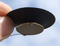
I think krafty said he'd fried one already, so maybe a bit of disassembly is in order here.
It's the upside of breaking things, that you find out how they work.
I did the same with a Visaton TW70 cone tweeter when my screwdriver slipped through the cone. Quite impressive inside. Proper rigid spider behind the cone. No ferrofluid. Interesting. Not cheap tat at all.
It's the upside of breaking things, that you find out how they work.
I did the same with a Visaton TW70 cone tweeter when my screwdriver slipped through the cone. Quite impressive inside. Proper rigid spider behind the cone. No ferrofluid. Interesting. Not cheap tat at all.
- Status
- This old topic is closed. If you want to reopen this topic, contact a moderator using the "Report Post" button.
- Home
- Loudspeakers
- Multi-Way
- Please check out my final circuit X/O with piezo