Here it is. Sorry to have posted with foreign words at first.
What do these numbers tell you now?
What do these numbers tell you now?
An externally hosted image should be here but it was not working when we last tested it.
Posting here a variation of the latest circuit. Moved R1 from paralel position to series (according to piezo datasheet, not frugal article). Shouldn't bear no audible difference, should it?
An externally hosted image should be here but it was not working when we last tested it.
That change would certainly measure quite differently, whether you can hear the change is another question entirelyPosting here a variation of the latest circuit. Moved R1 from paralel position to series (according to piezo datasheet, not frugal article). Shouldn't bear no audible difference, should it?
") .
.Ok but theoretically, which one is correct. Parallel or series?
You said that without a resistor in series, it would never been seen as a driver, and it would crossover at 2000 Hz.
Does this move of the resistor changes anything and accomplishes what it is supposed to accomplish?
You said that without a resistor in series, it would never been seen as a driver, and it would crossover at 2000 Hz.
Does this move of the resistor changes anything and accomplishes what it is supposed to accomplish?
Last edited:
1) Both are different approaches, each is "correct", but will sound and measure differently.1)Ok but theoretically, which one is correct. Parallel or series?
2)Does this move of the resistor changes anything and accomplishes what it is supposed to accomplish?
2) You are dealing with drivers that probably have little in common with the "frequency curve response" you posted in #25, with an unknown impedance, I can't help you decide anything without knowing both. Measure (or listen) and decide which accomplishes what it is supposed to accomplish better for you.
Have fun, good luck!
Art
So in this circuit, I decided to follow the exact quotes of the Frugal-Phile Article.
"... Looking from the amp, first the series crossover cap, say 4 uF, then the 22 ohm shunt from hot to ground, then a series cap of about 0.15 uF for 6 dB attenuation, and then a series resistor of about 30-50 ohms to tame the very top end, then the piezo itself..."
The 4uF cap is replaced by a 1.5uF, as it says that: "...For the smaller piezo units that cut off at 4-5 kHz, a series cap of 1.5 uF will do the trick..." and also says that 4uF cap is more for a horn type piezo.
I left out the 30-50 own, since with this piezo, the result removes the treble almost entirely.
An externally hosted image should be here but it was not working when we last tested it.
Ok, so, not giving up on this yet...
Just ordered more parts to experiment.
In the circuit above, it is more acceptable when you remove the 0,47uF cap, as it leaves really muffled. So I am reducing to 0,15uF as originally recommended by Frugal article. I am going to also test a 4.7uF in place of 1.5uF larger cap. I am maintaining the 22R on parallel for now.
As for a ending resistor on the final way to the piezo positive, I will not add anything right now, because the capacitor is atenuating enough already. If 0,15uF still holds the treble, I may just remove it and try the original 39 Ohm in there.
The tests this morning resulted in a very pleasant sound, kind of what I was looking for, so in the end, all of this craziness is kinda worth it.
Hey there Krafty,
Are the LeSon Piezos still available down there in Brazil? They are used in some instrument cabinets here in the US but other than that are pretty hard to find ...
You should know that the LeSons included a special audio transformer (or autoformer) inside of the casing that did a really good job of matching the high impedance of the Piezo element to a low impedance amp (providing a standard low impedance load such as 4 ohm or 8 ohm to your amplifier) , it is also how they achieved such high sensitivity ratings (100db+ @ 1w 1m).. That special step-up autoformer makes the LeSons much different than your standard Goldwood , CTS or GRS brand tweeters that i would more commonly find here in the United States ...
With that in mind the circuit that LeSon recommends actually makes a lot of sense, the series cap (connected to the tweeter) gives you your high-pass frequency, and lowering that capacitor's value will increase crossover frequency and likewise a higher value cap will give you a lower frequency crossover ... The series resistor before the cap acts as your attenuator and it looks like a value higher than 22 ohms will be necessary to match to your other driver which has such a low efficiency ..
Last edited:
Hi Matthew. Wow, I am really surprised to hear that about LeSon. Really. Yes, we still have these on market, LeSon is pretty present here. I bought them brand new. I am going to try to process everything that you just told me - sounds like more modifications are likely to happen here.
Ok, thanks. I will do the paralel one.
Hi, No, parallel is just plain wrong, rgds, sreten.
Note that knock off has an internal series capacitor.
Last edited:
Ok. Thanks for the tips, I really appreciate.
The LeSon datasheet specifies a 4.7uF cap and a 22R resistor in series.
@Matthew or others: when you say that I have to increase resistor value to mach the bass driver, is it because it is 86dB SPL and 22R on that resistor match to that level?
This is a bit confusing... in the first posts I thought it was 108dB minus 22dB to level it to 86dB (thinking of a ohm down for each dB). Now I just noticed, in the datasheet and as Matthew pointed out, 22R is for a sensitivity of 97dB. I still need to bring it down more 11 dB!? How do I calculate the right resistor value?
Last edited:
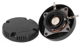
So, I opened up one piezo...
I didn't see any capacitor. The coil is soldered directly in the terminals.
I didn't want to open it fully, because the wiring is very tight and that means breaking the tweeter. I looked and looked all around, didn't see any capacitor. So, is it really missing? The coil, though looks longer than the previous post showing the example.
Everything changes again, right?
Oh well, taking to the last consequences... No capacitor at all.
An externally hosted image should be here but it was not working when we last tested it.
An externally hosted image should be here but it was not working when we last tested it.
An externally hosted image should be here but it was not working when we last tested it.
Krafty, it is ok if there is no capacitor inside of the tweeter's casing, it just means that you need to make sure to use a series cap inline, thats all, you can treat it as you would a normal dynamic (moving coil & magnet based) tweeter with a voicecoil .... The cap just blocks the lower frequencies, creating a crossover point, and increases power handling to reasonable levels by filtering-out the lower frequencies (blocks the mid & bass frequencies) which provides protection to your coil and reduces the likelihood of burning up your coil or damaging the element .....
Anyway, you should be able to set your ohm meter to a low range and connect the probes across the terminals of your LeSon tweeters and see something in the range of 3-8 ohms as you would with a normal voicecoil based tweeter or compression driver..
.. The chinese knockoff version of the Piezo with transformer used an internal cap so that an external one wasn't necessary, thats all ...
Im sorry to see that you disassembled your tweeter, i hope it goes back together without a problem ... Note: Interesting to see that the Piezo bender element itself is square in shape instead of the typical round shape
- Status
- This old topic is closed. If you want to reopen this topic, contact a moderator using the "Report Post" button.
- Home
- Loudspeakers
- Multi-Way
- Please check out my final circuit X/O with piezo