The SLCF is a well proven design that works better than most. It is not a CF and has none of the faults of one. Run with 70V rails the ECC88 will perform admirably in this circuit.
I agree that an EI transformer would be better and 50V versions are available from both farnell and Radionics.
Shoog
I agree that an EI transformer would be better and 50V versions are available from both farnell and Radionics.
Shoog
JBS,
Don't forget to acquire a filament trafo. Otherwise, "she no work". 6.3 VAC-CT/1 A. will do nicely. The CT allows you to bias the heaters off B+ by a voltage divider. Biasing the heaters lowers noise and keeps the heater to cathode potential inside published limits. Remember, you are stacking twin triode sections.
Imagine your talking to an idiot (And you are!) Do I need a seperate Transformer for the heater? or do I tap it off B+ somehow?
You need a seperate winding on the transformer. Or a seperate transformer for the heater. The reason you can't tap it off the b+ is because the heater has a much higher current demand than your average b+ tap can supply.Do I need a seperate Transformer for the heater? or do I tap it off B+ somehow?
If you go for the toroidal. You have one massive advantage over an EI transformer. And that is that you can simply wind your own seperate heater winding. Simply keep wrapping a thick wire around your toroidal (in the manner that the other windings are done) Until you measure 6,3VAC.
")
If you are using a toroidal and you have a few meters of magnet wire you could wind a filament supply onto the main transformer. This is easy but you need a bit of magnet wire.
Otherwise (and the better solution) is to buy a little transformer with a VA rating of about 20VA and a secondary of 6V. If it has twin secondaries you could split the triode stack into two seperate ECC88 and place the heaters at exactly the right potential for each. That is to say that both the CCS would be in one bottle with their heaters biased at -50V (-70V rail + 20V) and then the two cathode follower elements in the other bottle and the heater referenced to +20V. Valves always perform slightly better if their heaters are biased positive with respect to their cathodes.
I always run my heaters starved (ie 6V rather than 6.3V) because tube life increases dramatically and, within reason, linearity has been shown to improve. I ran PCC88's in my first SLCF at 6.3V when they were rated at 7.0V - not a problem and at that time the PCC88's I got were quality Bugle Boys at a fraction of the price of ECC88 Bugle Boys.
Shoog
Last edited:
I agree that an EI transformer would be better and 50V versions are available from both farnell and Radionics.
Shoog
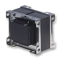
I dont know how I missed this:
--|MCF/T2950F|TRANSFORMER, 75VA, 2 X 50V | CPC
An externally hosted image should be here but it was not working when we last tested it.
* TRANSFORMER, 75VA, 2 X 50V
* Mounting Type:Chassis
* Power per Secondary Winding:37.5VA
* Secondary Current Rating:750mA
* Secondary Voltages:0-50, 0-50
* Transformer Type:Low Voltage
* AC Power:75VA
* Approval Bodies:EN60065, EN60742 (requires additional fuse protection)
* External Depth:75mm
* External Length / Height:67mm
* External Width:79mm
* Fixing Centres LxW:54 x 54
* Isolation voltage:3.75kV
* Max Output 2 Voltage:50V
* Output Voltage:50V
* Single Primary Voltage:230V
* Supply Voltage AC:230V
* Type:230V Single Primary
* Weight:1.5kg
* Current Rating:0.75A
* Regulation:10%
* Transformer Fixing Style:Frame
It only has about 3mm of headroom in my chasis but it should fit!
I'd rather keep one valve per channel if poss, I'd like a dual mono construction on this one, it'll allow me to make all my mistakes on one side before starting the other.Otherwise (and the better solution) is to buy a little transformer with a VA rating of about 20VA and a secondary of 6V.
If it has twin secondaries you could split the triode stack into two seperate ECC88 and place the heaters at exactly the right potential for each. That is to say that both the CCS would be in one bottle with their heaters biased at -50V (-70V rail + 20V) and then the two cathode follower elements in the other bottle and the heater referenced to +20V. Valves always perform slightly better if their heaters are biased positive with respect to their cathodes.
Could you clarify some stuff about the heater.
From the data sheet:
I have two heaters per tube pin 4 and 5; and a screen that is tapped of the ctr of the two heater elements Pin 9.
I have a Uf of 6.3v, is that ac, dc or does it not matter?
Is it 6.3v per element (e.g. Pin4-Pin9 = 6.3v), or 6.3v for both (i.e. Pin4-Pin5 = 6.3v)?
U+k/f- = 120v, The difference between a Posativly biased kathod and its heater must be within +120v (Worst Case)?
U-K/f+ = 60v The difference between a Negativly biased kathod and its heater must be within -60v (Worst Case)?
You will want to tie the two pins 4 & 5 together and place the heater supply across pins 4+5 and 9. Reference the heaters to -50V by taking a voltage divider between the neg rail and ground. Heaters can be either AC or DC, but there is no advantage to going DC, so just keep it AC.
Shoog
Shoog
Have a look at the datasheet (Google up TDSL software in install it, it's a free and an invaluable resource to anyone tinkering with tubes, remember to downlaod the updated .exe as well). You will notice that pin 9 is NOT connected to filament anywhere (unlike in, say, 12A*7).
Heater voltage is specified as RMS value, therefore 6.3V AC (which is approx. 9V p-t-p) or 6.3V DC will work. If you lift the heaters above the cathode as Shoog suggested, you shouldn't be getting any interference from the filament (cathode rectification).
You got the last two right, except that some datasheets indicate lower Uk-f+ (50V). Keep everything connected as Shoog suggested and you'll be just fine.
The SLCF is a well proven design that works better than most. It is not a CF and has none of the faults of one.
Well proven to who (whom?)? It might be your and a some others opinion that it works better than most but thats all.
And how can you say it is not a CF? Even the name implies it is! I would say it is a super-CF with, if I understand it right, bootstrapping.
Here we have an old(1954) patent http://www.freepatentsonline.com/2795654.pdf that is close to, or identical to the SLCF. George at tubelab tried something like this some year ago.
Last edited:
You will want to tie the two pins 4 & 5 together and place the heater supply across pins 4+5 and 9.
Shoog
You will notice that pin 9 is NOT connected to filament anywhere (unlike in, say, 12A*7).......... Keep everything connected as Shoog suggested and you'll be just fine.
Yes; sorry Shoog, the screen does not ctr tap the filament, so should i connect accross 4 and 5?
Sorry I should have checked the datasheet before commenting on the pin connection, my mistake. Yes between 4 and 5 then with the bias off the voltage divider connected to pin 4.
All I can say about the SLCF is it works for me and is a consistent winner with reviewers of the Vacuum State products. Of course its nothing new (who claimed it was) - it was developed as a particularly linear input stage for scope - which should tell you that it does its job well above what is needed for audio applications. Build it and see, that's the only proof which is worth talking about. It certainly performs better than a bare CF and is one of the only buffer stages which doesn't employ lots of loop feedback to kill the gain.
Shoog
doesn't employ lots of loop feedback to kill the gain
Hey Shoog,
A CF is close to 100% feedback. Must be the same as lots of loop feedback
.The problems with amps you refer to are probably that they have feedback over more than one gainstage. And that ain´t good.....
There is a good BBC book about feedback at Pete Milletts site. Great stuff, check it out!
How about this as a suitable transformer;
Walsall Transformers | Transformers | Transformers | Control Panel Transformers | Laminated |WT1993
or this if you really wanted to up the rails;
Block | Transformers | Transformers | Safety Site Transformers | Wall Mounting and Floor Standing |TIM 60
This would still be doable with the caps you have, a stack of three would be needed with a 2K2 resistors straight after the rectifiers. This would make the silicone diodes behave very much like a valve rectifier, and would kill those charging spikes dead.
Shoog
Last edited:
Hey Shoog,
A CF is close to 100% feedback. Must be the same as lots of loop feedback
The problems with amps you refer to are probably that they have feedback over more than one gainstage. And that ain´t good.....
There is a good BBC book about feedback at Pete Milletts site. Great stuff, check it out!
The analysis I have seen is that the SLCF removes the feedback from the CF, turning the output tube into a diode with current gain. I would be interested in a critique of this idea.
Shoog
How about this as a suitable transformer;
Walsall Transformers | Transformers | Transformers | Control Panel Transformers | Laminated |WT1993
or this if you really wanted to up the rails;
Block | Transformers | Transformers | Safety Site Transformers | Wall Mounting and Floor Standing |TIM 60
This would still be doable with the caps you have, a stack of three would be needed with a 2K2 resistors straight after the rectifiers. This would make the silicone diodes behave very much like a valve rectifier, and would kill those charging spikes dead.
Shoog
Thanks, but both too big unfortunatly, I'm limited too about 70mm headroom if I want to keep the chasis in one piece.
A lot of my parts started arriving today, Carbon resistors, tag boards, Valves and valve holders are all in.
I ordered the valves from ebay, they're not actuall marked ECC88 or 6922 they're marked 6H23n (in russian cyrillic) but they were the right price and they have a rocket on them! I think they sould work can anyone confirm?
I ordered the valves from ebay, they're not actuall marked ECC88 or 6922 they're marked 6H23n (in russian cyrillic) but they were the right price and they have a rocket on them! I think they sould work can anyone confirm?
Last edited:
They have an excellent reputation. Never tried them myself though.6H23n
Lars,
I and everyone who has built it, says the SLCF is a major advance over a plain CF as a output stage in a audio system.
But thanks for that patent - never seen it before.
I wrote up the SLCF for the TubePreamp CookBook as it worked for me. I got the idea (and never claimed otherwise) from Valley & Wallmann - although they never used both the CCs and the bootstrap in the same circuit.
>>The analysis I have seen is that the SLCF removes the feedback from the CF, turning the output tube into a diode with current gain. I would be interested in a critique of this idea.<<
Who the hell made that analysis? Sounds weird to me but would need to see the whole thing before I could comment accurately.
To me, the CCS keeps the pre-signal current constant, and the bootstrap keeps the anode/cathode voltage constant, so the only variation in the actual CF tube is the current changes into the load R from signal changes. All else stays as stable as possible.
And it IS a CF, as the cathode "follows" the grid - which fits the description pretty closely - no?
Regards, Allen
Hey Allen,
Tried a theoretic analyze of the McDonald/SLCF and the differencies seem to be what McDonald said, a no loss CF and what the name SLCF(superlinear?) implies, a more linear CF than the std with at least ten times lower THD. If this shows up in better sonics it is a good thing.
If McDonald had had FETs, I believe he would have used them as CCS´s!
Tried a theoretic analyze of the McDonald/SLCF and the differencies seem to be what McDonald said, a no loss CF and what the name SLCF(superlinear?) implies, a more linear CF than the std with at least ten times lower THD. If this shows up in better sonics it is a good thing.
If McDonald had had FETs, I believe he would have used them as CCS´s
!I and everyone who has built it, says the SLCF is a major advance over a plain CF as a output stage in a audio system.
Well, not everyone. I played with them and found no real advantage for the intended use, i.e., preamp output stages that swing a few volts at most, over CFs.
- Status
- This old topic is closed. If you want to reopen this topic, contact a moderator using the "Report Post" button.
- Home
- Amplifiers
- Tubes / Valves
- Low Voltage Tube Preamplifier