Ground associated with the amplifier circuit, but excluding the power supply elements. That is such things as grid earth, output earth reference, input socket earth. This keeps the delicate signal currents isolated from the big ugly power supply and chassis earths which would tend to introduce hum. I tend to use a small cross section wire to take this ground pin to the power supply star ground (always use a star ground - never anything else) and finally a larger gauge wire to the power socket earth. Think of earth current as water flowing through the path of least resistance - it is your job to make certain that that flow is always away from the small signal ground..
Shoog
Shoog
I got the donor amp this morning:
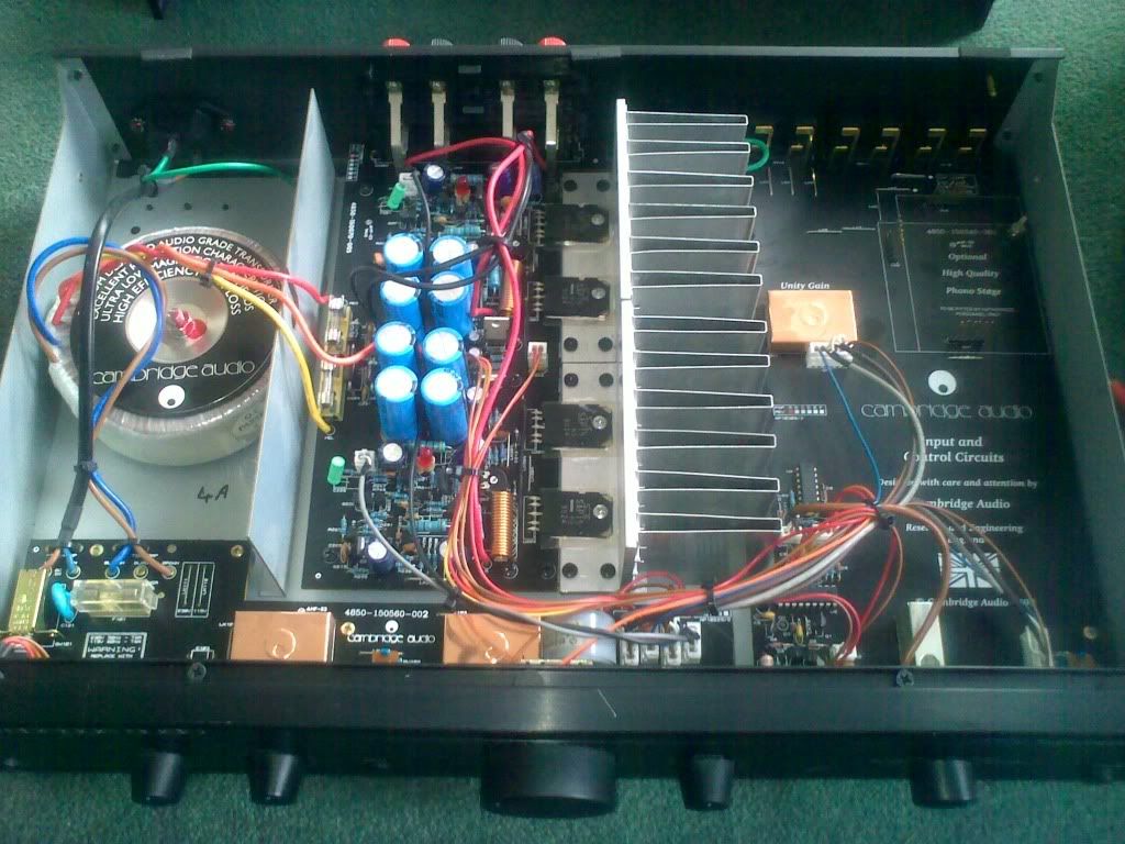
I've been staring at it for hours, trying to decide on a layout.
The PSU and power amp stage are crammed together on the same PCB so I've removed the whole thing;
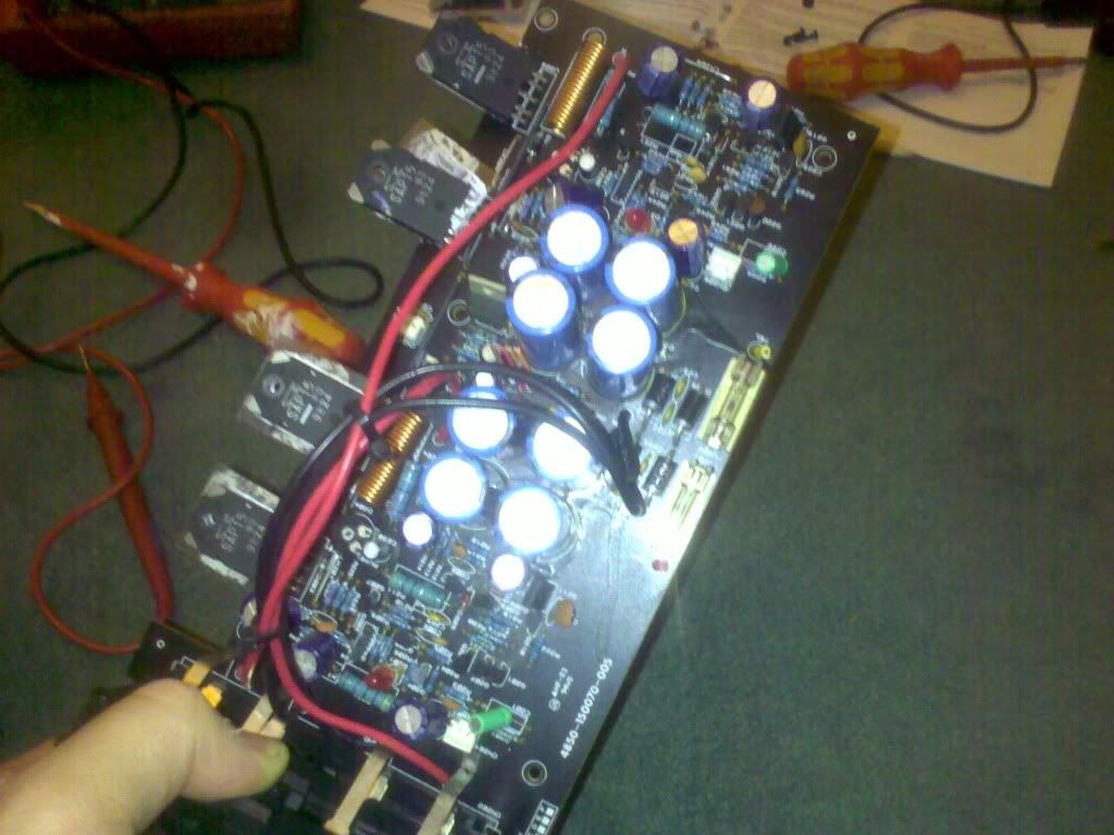
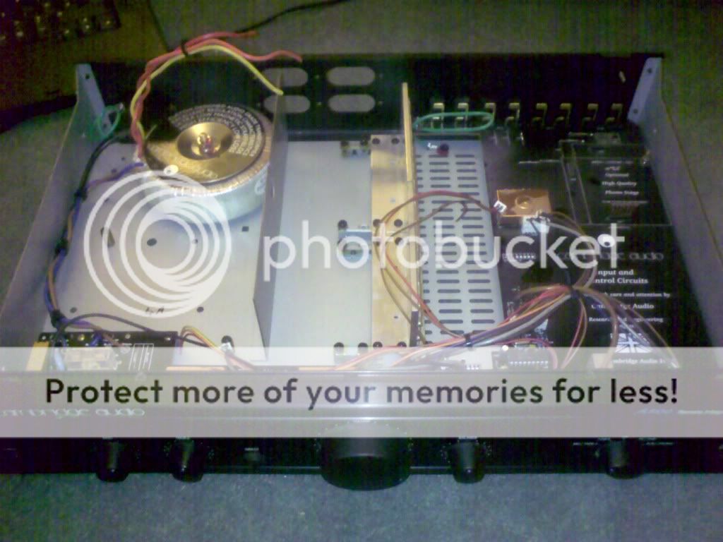
I'm going to remove the PSU components and fit them into the same section as the Toroid which I've moved and made a bigger partition:
I've been staring at it for hours, trying to decide on a layout.
The PSU and power amp stage are crammed together on the same PCB so I've removed the whole thing;
I'm going to remove the PSU components and fit them into the same section as the Toroid which I've moved and made a bigger partition:
I wouldn't scrimp on the 1uf cap, though you can probably use anything from 0.1uf upwards. Salvage from a switch mode power supply is definately an option, they also make good doners of quality rectifiers.
What did the power transformer pan out at. You should be able to salvage those caps if you are careful. Look as though you might as well go ahead and build El Duttmans higher voltage power supply.
That L-Shaped bracket looks as though it should make a good horizontal mounting point for your valve sockets, and will also take the MOSFETs.
Whats the brand of the volume control.
All looks good.
Shoog
Well! that went badly; I just made a load more work for myself by smoking the toroid!
When I re-positioned it I bolted it down on top of a sharp chasis screw, short circuit, smoke, me big idiot etc.
Where's a good source of cheap transformers? I guess it gives me an excuse to use a more suitible voltage some regulated 45v rails would be good (All my large caps are rated at 50v)
Could really do with some pointers towards transformers though!
When I re-positioned it I bolted it down on top of a sharp chasis screw, short circuit, smoke, me big idiot etc.
Where's a good source of cheap transformers? I guess it gives me an excuse to use a more suitible voltage some regulated 45v rails would be good (All my large caps are rated at 50v)
thats exactly what I was thinking!That L-Shaped bracket looks as though it should make a good horizontal mounting point for your valve sockets, and will also take the MOSFETs.
Cant make it out, v cheap and v nasty i assume, there's a remote control motor bolted to it at the moment, I thought I'd leave the motor attached for now, it's not hurting anything and probably providing some mechanical damping; will upgrade at some point in the future.Whats the brand of the volume control.Shoog
Could really do with some pointers towards transformers though!
Allen, forgive my keyboard jockey-ing. But did you ever cascode the mosfets? And what mosfet did you use?Jammy,
Didn't you read what I said about using not a MOSFET as the botstrap upper device?
Or do you in your wisdom chose to ignore my experience?
Kind regards,
Bas
Jammy,
Didn't you read what I said about using not a MOSFET as the botstrap upper device?
Or do you in your wisdom chose to ignore my experience?
Regards, Allen
Sorry Allen
I did mean to respond, but got side tracked; I have been thinking about it. I have the MOSFET handy so I thought I'd just carry on with that for the moment and when it's up and running I will try a BJT circuit in it's place as sugested, or perhaps a valve.
I'm trying to build in such a way that I can easily swap components to try things out. I'm a little pre-occupied with my clutzy school-boy error on PSU at the moment. But I will come back to the boot-strap. Thanks for your input, I really wasn't trying to ignore it.
Thats a very unfortunate accident with the toroidal.
Do you have access to other junked equipment. EI is probably better in this application as it rejects line hash better. Current demand is small so transformers don't need to be big. You can even con figure for back to back transformers which allows for the use of almost any pair of transformers, and line rejection is even better.
As EL Duttman showed in his power supply - you want to stack your caps in series (with balancing resistors) in order to allow higher voltage operation. Do not feel tied to your 50V, think stacked for 100V which will allow for the +/-70V rails you want.
Shoog
Bas,
Cascoding MOSFETs was not tried, the circuit is complete enough already.
And I always thought a MOSFET was inherently a cascode from it's construction.
The tube does the job WONDERFULLY, so I'm not interested in screwing around trying to make a flawed component work when I have a much superior component readily available. Life is too short for such **.
Regards, Allen
Why not go custom. At least in the Netherlands that is not more expensive. And you can then also specify an electrostatic screen which should be standard for audio applications IMO.Off the shelf I'm really struggling to do better than a transformer with 55v rails. can anyone help? I need ideally a 240v transformer with 2 out rails between 70 and 100v
Also aren't you guys in the UK going down to 230? Because in Europe we are going up to 230. And I still see everyone talking about 220. A pet peeve of mine.
How much current do you want it to be able to supply?I need ideally a 240v transformer with 2 out rails between 70 and 100v
Last edited:
Fair enough.he tube does the job WONDERFULLY, so I'm not interested in screwing around trying to make a flawed component work when I have a much superior component readily available. Life is too short for such **.
")
Or try IXYS IXTP01N100D depletion mode mosfet cascaded.I have the MOSFET handy so I thought I'd just carry on with that for the moment and when it's up and running I will try a BJT circuit in it's place as sugested, or perhaps a valve.
Why not go custom. At least in the Netherlands that is not more expensive. And you can then also specify an electrostatic screen which should be standard for audio applications IMO.
Also aren't you guys in the UK going down to 230? Because in Europe we are going up to 230. And I still see everyone talking about 220. A pet peeve of mine.
How much current do you want it to be able to supply?
very little current really it's just for a unity gain Pre-amp;
As for the 230VAC thing in the uk. We arn't actually changing the voltage, just the stated tollerence! i.e. we used to supply 240vac +/- 5% we now supply 230 V +10% −6%. And It will probably stay that way. It's still 240 if you meter the wall here anyway.
My best bet at keeping it cheap is probably this:
MULTICOMP|MCTA050/55|50VA TOROIDAL 2X55V | CPC
* 50VA TOROIDAL 2X55V
* Mounting Type:Chassis
* Power per Secondary Winding:25VA
* Primary Voltages:0-115, 0-115
* SVHC:No SVHC
* Secondary Voltages:0-55, 0-55
* Transformer Type:Toroidal
* AC Power:50VA
* Approval Bodies:EN60950, EN60742, UL Recognised
* Bolt Hole Diameter:5mm
* Bolt Length:40mm
* Current Rating:0.45A
* External Diameter:76mm
* External Length / Height:30mm
* Max Output 2 Voltage:55V
* Output Voltage:55V
* Regulation:11.8%
* Temperature Rise:48°C
I should be able to get over +/-70VDC out of this!
MULTICOMP|MCTA050/55|50VA TOROIDAL 2X55V | CPC
An externally hosted image should be here but it was not working when we last tested it.
* 50VA TOROIDAL 2X55V
* Mounting Type:Chassis
* Power per Secondary Winding:25VA
* Primary Voltages:0-115, 0-115
* SVHC:No SVHC
* Secondary Voltages:0-55, 0-55
* Transformer Type:Toroidal
* AC Power:50VA
* Approval Bodies:EN60950, EN60742, UL Recognised
* Bolt Hole Diameter:5mm
* Bolt Length:40mm
* Current Rating:0.45A
* External Diameter:76mm
* External Length / Height:30mm
* Max Output 2 Voltage:55V
* Output Voltage:55V
* Regulation:11.8%
* Temperature Rise:48°C
I should be able to get over +/-70VDC out of this!
My best bet at keeping it cheap is probably this:
MULTICOMP|MCTA050/55|50VA TOROIDAL 2X55V | CPC
An externally hosted image should be here but it was not working when we last tested it.
* 50VA TOROIDAL 2X55V
* Mounting Type:Chassis
* Power per Secondary Winding:25VA
* Primary Voltages:0-115, 0-115
* SVHC:No SVHC
* Secondary Voltages:0-55, 0-55
* Transformer Type:Toroidal
* AC Power:50VA
* Approval Bodies:EN60950, EN60742, UL Recognised
* Bolt Hole Diameter:5mm
* Bolt Length:40mm
* Current Rating:0.45A
* External Diameter:76mm
* External Length / Height:30mm
* Max Output 2 Voltage:55V
* Output Voltage:55V
* Regulation:11.8%
* Temperature Rise:48°C
I should be able to get over +/-70VDC out of this!
Looks good.
Shoog
JBS,
Don't forget to acquire a filament trafo. Otherwise, "she no work". 6.3 VAC-CT/1 A. will do nicely. The CT allows you to bias the heaters off B+ by a voltage divider. Biasing the heaters lowers noise and keeps the heater to cathode potential inside published limits. Remember, you are stacking twin triode sections.
Don't forget to acquire a filament trafo. Otherwise, "she no work". 6.3 VAC-CT/1 A. will do nicely. The CT allows you to bias the heaters off B+ by a voltage divider. Biasing the heaters lowers noise and keeps the heater to cathode potential inside published limits. Remember, you are stacking twin triode sections.
I'm not trying to dampen your enthusiasm. But if there was one way to design a transformer that would ensure the maximum amount of garbage on the mains supply to spill into your circuit. That would be a toroidal transformer. Use only if you can't find anything else.My best bet at keeping it cheap is probably this:
MULTICOMP|MCTA050/55|50VA TOROIDAL 2X55V | CPC
- Status
- This old topic is closed. If you want to reopen this topic, contact a moderator using the "Report Post" button.
- Home
- Amplifiers
- Tubes / Valves
- Low Voltage Tube Preamplifier