I've recently accuired a Cambridge audio A500 which apparently has a faulty power amp stage, I could fix it, but I have no real use for it; however it does have +/-45v PSU and a nice set of RCA connections selector switches and volume controle that I would like to make use of; the pre-amp stage is rather run of the mill so I cant see any advanteage to using it in my system over my NAD 3130s pre.
I've also recently been looking at the Bottlehead Quickie kit, a battery powered preamp; now I know nothing about valve stuff but this bit of kit seems to sugest that if your making a low power amplifier (pre-amplifier) then you don't need the high voltages asociated with Tube power amps; would this be right?
Could I build somthing like the quickie into the CA Chasis using the CA's powersupply and make myself a cheap valve pre?
The quickie seems to consiste of two valves and a handfull of caps and resistors, most of the $99 price tag goes on the fixtures fittings knobs etc so buying the kit would be a waste of money for this project; the Schmatic is not availible on it's own, could anyone sugest a circuit of easy to source components i could use to create a pre at these voltages?
Note that there are plenty of space charge tubes avaliable, which aren't "cool" enough yet to be used as mainstream as ECC86, even though they run with low voltage as well (12V on anode). I won't list any names because it'd be a shame to see the ePay prices of these skyrocket, but some Google searching will lead you to a very nice webpage, listing many commonly avaliable space charge tube types. What you're looking for are either sharp cutoff pentodes or triodes in any combination with other tubes (FM detector diodes, remote cut-off pentodes etc.) in same envelope and just leave those other portions doing nothing. You will want to avoid 12K5 (its price has gone up significantly already) and one of the preamp tubes the name of which escapes me right now but then again you're only interested in preamplification so any triode that looks linear enough will do just fine !
Also remember that vast majority of power will be wasted on heating, not the tube operation. This is even more true with the space charge tubes (10% of power going info amplification and 90% into heating) so make sure you get a decent supply !
Also remember that vast majority of power will be wasted on heating, not the tube operation. This is even more true with the space charge tubes (10% of power going info amplification and 90% into heating) so make sure you get a decent supply !
At +/-45VDC, you have more than enough juice to keep ECC88/6DJ8/6922/6N23P pretty happy (and there are reports of low distortion even as low as +24VDC). You can search a whole host of preamp designs based on those.
A whole host indeed! too many infact, and some seem impossibly simple! I'm trying to read up on the tube to make an informed choice but I could do with a solid start, if anyone could sugest a circuit that's tried and tested for my first go I'd apriciate it!
Cheers Arnulf, could you PM me the URL!I won't list any names because it'd be a shame to see the ePay prices of these skyrocket, but some Google searching will lead you to a very nice webpage, listing many commonly avaliable space charge tube types.
I've recently accuired a Cambridge audio A500 which apparently has a faulty power amp stage, I could fix it, but I have no real use for it; however it does have +/-45v PSU and a nice set of RCA connections selector switches and volume controle that I would like to make use of; the pre-amp stage is rather run of the mill so I cant see any advanteage to using it in my system over my NAD 3130s pre.
I've also recently been looking at the Bottlehead Quickie kit, a battery powered preamp; now I know nothing about valve stuff but this bit of kit seems to sugest that if your making a low power amplifier (pre-amplifier) then you don't need the high voltages asociated with Tube power amps; would this be right?
Could I build somthing like the quickie into the CA Chasis using the CA's powersupply and make myself a cheap valve pre?
The quickie seems to consiste of two valves and a handfull of caps and resistors, most of the $99 price tag goes on the fixtures fittings knobs etc so buying the kit would be a waste of money for this project; the Schmatic is not availible on it's own, could anyone sugest a circuit of easy to source components i could use to create a pre at these voltages?
JBS,
Some of your assumptions are wrong, but you should be able to make a decent line stage out of the defunct "solid scrape" unit.
The 45-0-45 you give will rise, when asked to provide only a few mA. of current, instead of the considerably larger draw the OEM planned on. To get a feel for what will actually occur, disconnect the PSU from the "dead" circuitry and measure the unloaded voltage.
Gain structure requirements will govern what you do. What drive level does the power amp you plan to use require? If, as is frequently the case, less than 2 VRMS are needed, a near unity gain setup will serve you well. Remember, a "standard" CDP produces 2 VRMS peak.
PSU's are naturally differential. We make them single ended or bipolar by where we place the ground connection. If you move the ground connection to the negative end, you get a highly satisfactory B+ supply for use with a 6922. A single 6922 set up as cathode followers (1/channel) fills the "unity" gain role well.
Let's resolve the gain structure issue before moving forward.
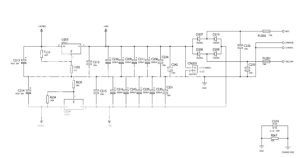
I'm afraid I havent phisically got the thing yet, but I have the circuit diagram. PSU is +/-45v unregulated, it comes with LM3x7regulators, set by default to 30v, but this could be easily adjusted to +/-37v or replaced with higher voltage regs to get +/-43v. Or most possibly higher when as you say the voltage will rise unloaded.[/QUOTE]JBS,
Some of your assumptions are wrong, but you should be able to make a decent line stage out of the defunct "solid scrape" unit.
The 45-0-45 you give will rise, when asked to provide only a few mA. of current, instead of the considerably larger draw the OEM planned on. To get a feel for what will actually occur, disconnect the PSU from the "dead" circuitry and measure the unloaded voltage.
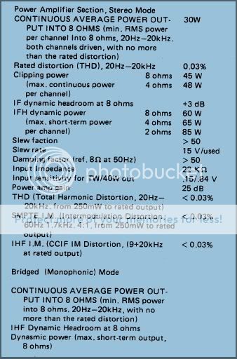
I'd say your right; The service manual for the Power stage of the NAD 3130 states:Gain structure requirements will govern what you do. What drive level does the power amp you plan to use require? If, as is frequently the case, less than 2 VRMS are needed, a near unity gain setup will serve you well. Remember, a "standard" CDP produces 2 VRMS peak.
Input Impedance = 22Kohm
Input sensitivity for TW/40W out = .15/.84 V (perhaps you could clarify for me exactly what that means, TW??)
You should manage 125V from your transformer. If you can find some simple chokes then you can keep almost all of this. I regularly use florescent light ballasts as chokes in preamp duties. Very cheap and readily available from lighting suppliers.
A version of the Aikido using ECC88's would be my first choice. 60V on each plate is just adequate. Forget the ECC86, because the 24V Aikido has turned prices stupid.
Shoog
A version of the Aikido using ECC88's would be my first choice. 60V on each plate is just adequate. Forget the ECC86, because the 24V Aikido has turned prices stupid.
Shoog
You should manage 125V from your transformer. If you can find some simple chokes then you can keep almost all of this. I regularly use florescent light ballasts as chokes in preamp duties. Very cheap and readily available from lighting suppliers.
A version of the Aikido using ECC88's would be my first choice. 60V on each plate is just adequate. Forget the ECC86, because the 24V Aikido has turned prices stupid.
Shoog
I like the sound of this, there seems to be alot of easy to follow info here: http://www.tubecad.com/Nine-Pin_Aikido_PCB.pdf and the the ECC88's seem easy to get hold of; I just need to see how much voltage I can get out of the PSU. some more info on the light ballasts choke would be good.
These are what you are looking for;
http://upload.wikimedia.org/wikipedia/commons/8/80/LAjaHID.jpg
Every single strip light will have one, and so can easily be got as replacements from lighting suppliers. About $10.00 a throw.
Shoog
http://upload.wikimedia.org/wikipedia/commons/8/80/LAjaHID.jpg
Every single strip light will have one, and so can easily be got as replacements from lighting suppliers. About $10.00 a throw.
Shoog
If you have that much capacitance then you shouldn't need a choke.
Traditionally the choke went between two stages of capacitance and resisted variations in current change- hence producing less ripple on the supply. Now days, since capacitance is so cheap, most people use brute force and huge capacitance to achieve the same thing, or substitute a resistor for the choke where they have voltage to spare. Since you are tight on voltage - hence the suggestion of using the choke.
Chokes in themselves have intrinsic high frequency hash rejection which will tend to reduce nasty artifacts in the final signal. They also have higher impedance at high frequencies which tends to make the sounjd slightly softer and more rounded to my ear. I like the effects to such an extent that I rarely build anything without choke power supply filtering somewhere.
Others prefer active regulation, but my penny says that active regulation has to be very good not to adversly effect the sound.
Shoog
Hi,Shoog what are the watt of choke you are using?
I have used all sorts. In one or two designs I have used the very small ones which came out of the earliest Compact Florescent Bulbs (about 2inchs long).
In other projects I have had great success with using 100Watt rated ballasts in front end filters, and on my main preamp. 100W will be overkill, but the cost difference is minimal on smaller units. I have heard of people using them as plate chokes in parafeed output stages so they must have reasonable henries and current capability. Unfortunately I haven't tested this empirically.
I have also found Microwave Oven Transformers work well as chokes (though their big and ugly). The great thing is they still have inductance when passing 0.5A. I personally cannot think of any other choke that is generally available with that sort of current capability, and for salvage price.
Shoog
You should manage 125V from your transformer. If you can find some simple chokes then you can keep almost all of this. I regularly use florescent light ballasts as chokes in preamp duties. Very cheap and readily available from lighting suppliers.
A version of the Aikido using ECC88's would be my first choice. 60V on each plate is just adequate. Forget the ECC86, because the 24V Aikido has turned prices stupid.
Shoog
Hey Shoog
I've been looking through the Aikido doc here: http://www.tubecad.com/Nine-Pin_Aikido_PCB.pdf and i'm a bit confused by the gain figures; at the end of this guide there is a table of tubes and B+ voltages looking at the ECC88 @ 100v line it specs an input gain of 23.5dB and an output gain of -0.39db (total 23.11db). I would have thought that a pre amp would be unity gain of 1. Am i missing somthing? It's a long time since i've needed this dB stuff and I'm very rusty.
That represents a 15x voltage gain (ie for 1V in you get 15V out). Of course the gain you actually see will be dictated by the position of your input pot - so you will see somewhere between 0-15x voltage gain).
If you want unity gain - then surprisingly that is much more difficult to achieve. You can either build a simple Cathode follower (with 100% degenerative feedback and all that implies in terms of sound quality), or build a preamp with gain and kill it with global feedback (with all that entails in terms of sound quality).
There is the Super Linear Cathode follower as an alternative, but its difficult to implement with just 125V - though it can be done ( I have done it).
Choices, Choices.
Shoog
That represents a 15x voltage gain (ie for 1V in you get 15V out). Of course the gain you actually see will be dictated by the position of your input pot - so you will see somewhere between 0-15x voltage gain).
If you want unity gain - then surprisingly that is much more difficult to achieve. You can either build a simple Cathode follower (with 100% degenerative feedback and all that implies in terms of sound quality), or build a preamp with gain and kill it with global feedback (with all that entails in terms of sound quality).
There is the Super Linear Cathode follower as an alternative, but its difficult to implement with just 125V - though it can be done ( I have done it).
Choices, Choices.
Shoog
I'm a bit confused now, i'd always assumed very litle gain with pre-amps; But I suppose as long as you keep a Log volume pot turned down it dosent matter!
The Specs of my Power Amplifier (NAD 3130 Power stage) states:
Input sensitivity for TW/40W out = .15/.84 V (perhaps you could clarify for me exactly what that means, TW??).
Last edited:
JBS,
Gain structure, gain structure, gain structure! An Aikido is a voltage amplifier, which is exactly what you don't need. Less than 1 VRMS at the power amp's I/P drives it to full power O/P. So, the 2 VRMS a "standard" CDP can produce will drive the amp well into clipping. As I stated previously, you need a buffered volume control. A buffered volume control in tube terms is a cathode follower.
IMO, the best cathode follower setup requires a bipolar PSU. When a bipolar PSU is employed, only 1 cap., at the preamp's O/P, is in the signal path. Advantage will be taken of the fact the the power trafo in situ is vastly oversized for the task assigned. A PSU of approx. 100-0-100 will be constructed. Look carefully and you will see that the OEM 45-0-45 supply is, in fact, a pair of back to back full wave center tapped supplies. To get "100"-0-"100", the rectifier winding's CT is tied off and back to back half wave supplies are employed. Because the power trafo is comparatively huge, the large 1st filter caps. needed are not problematic. AAMOF, the arrangement works quite well. Both halves of the AC cycle are passed by diodes and no "standing" DC is presented to the power trafo.")
Large 1st filter caps. come with their own set of baggage. Implicit in the tiny conduction angle is a very sharp triangular ripple waveform. Fourier's theorem tells that sharp periodic waveforms contain lots of ripple overtone components. Those overtones extend up well into RF. Immediately following the 1st filter cap. of each rail (B+/B-) is a "hash" filter made from a RF choke and a 1000 pF. NPO ceramic capacitor. A "hash" filter "dulls" the ripple waveform to the point a "classic" LC section can finish things up. The many turns of wire in PSU filter chokes create enough capacitance to short the choke out a high frequencies. It's not a problem if RF energy has been killed off before the "juice" arrives at the high inductance choke.
Gain structure, gain structure, gain structure! An Aikido is a voltage amplifier, which is exactly what you don't need. Less than 1 VRMS at the power amp's I/P drives it to full power O/P. So, the 2 VRMS a "standard" CDP can produce will drive the amp well into clipping. As I stated previously, you need a buffered volume control. A buffered volume control in tube terms is a cathode follower.
IMO, the best cathode follower setup requires a bipolar PSU. When a bipolar PSU is employed, only 1 cap., at the preamp's O/P, is in the signal path. Advantage will be taken of the fact the the power trafo in situ is vastly oversized for the task assigned. A PSU of approx. 100-0-100 will be constructed. Look carefully and you will see that the OEM 45-0-45 supply is, in fact, a pair of back to back full wave center tapped supplies. To get "100"-0-"100", the rectifier winding's CT is tied off and back to back half wave supplies are employed. Because the power trafo is comparatively huge, the large 1st filter caps. needed are not problematic. AAMOF, the arrangement works quite well. Both halves of the AC cycle are passed by diodes and no "standing" DC is presented to the power trafo.
Large 1st filter caps. come with their own set of baggage. Implicit in the tiny conduction angle is a very sharp triangular ripple waveform. Fourier's theorem tells that sharp periodic waveforms contain lots of ripple overtone components. Those overtones extend up well into RF. Immediately following the 1st filter cap. of each rail (B+/B-) is a "hash" filter made from a RF choke and a 1000 pF. NPO ceramic capacitor. A "hash" filter "dulls" the ripple waveform to the point a "classic" LC section can finish things up. The many turns of wire in PSU filter chokes create enough capacitance to short the choke out a high frequencies. It's not a problem if RF energy has been killed off before the "juice" arrives at the high inductance choke.
Since it seems you need a unity gain buffer I would recommend the split rail and the front end of the JLTi Gain lone;
http://www.customanalogue.com/jlti_mark_2.htm#This is a simplified Schematic Diagram:
This doesn't have component values, but they are fairly easy to work out. It is the best cathode follower because it removes the degenerative feedback. I built a version - but used a MOSFET at the top which simplifies the design slightly.
decibels gain is calculated by the following formula;
db Gain = 20 x log (Output Voltage/Input Voltage)
Shoog
When a bipolar PSU is employed, only 1 cap., at the preamp's O/P, is in the signal path.
With a bipolar supply, you can move that cap to the preamp's input and thus use a much smaller cap.
- Status
- This old topic is closed. If you want to reopen this topic, contact a moderator using the "Report Post" button.
- Home
- Amplifiers
- Tubes / Valves
- Low Voltage Tube Preamplifier