So your saying if I remove the ctr tapping from the transformer, the bridge will see two half wave 100v supplies which it will rectify to 100-0-100! Genius.JBS,
To get "100"-0-"100", the rectifier winding's CT is tied off and back to back half wave supplies are employed. Because the power trafo is comparatively huge, the large 1st filter caps. needed are not problematic. AAMOF, the arrangement works quite well. Both halves of the AC cycle are passed by diodes and no "standing" DC is presented to the power trafo.")
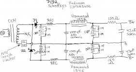
Large 1st filter caps. come with their own set of baggage. Implicit in the tiny conduction angle is a very sharp triangular ripple waveform. Fourier's theorem tells that sharp periodic waveforms contain lots of ripple overtone components. Those overtones extend up well into RF. Immediately following the 1st filter cap. of each rail (B+/B-) is a "hash" filter made from a RF choke and a 1000 pF. NPO ceramic capacitor. A "hash" filter "dulls" the ripple waveform to the point a "classic" LC section can finish things up. The many turns of wire in PSU filter chokes create enough capacitance to short the choke out a high frequencies. It's not a problem if RF energy has been killed off before the "juice" arrives at the high inductance choke.
I'm not so sure what your saying here, is it that if i do the above I might have a problem with the HF noise and should fit a harsh filter and an LC filter, rather than rely on the caps?
Looks good, and a transistor! (I feel safer already) but I could do with a start working out the component values is the design of this circuit covered anywhere? what voltage/tubes did you use?Since it seems you need a unity gain buffer I would recommend the split rail and the front end of the JLTi Gain lone;
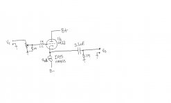
JLTi MK2 is a simplified Schematic Diagram:
This doesn't have component values, but they are fairly easy to work out. It is the best cathode follower because it removes the degenerative feedback. I built a version - but used a MOSFET at the top which simplifies the design slightly.
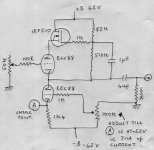
Here is my suggested SLCF unity gain preamp. I have assumed that the rails will pan out at +/-62V (45VAC*1.414).
The Bottom triode works as a CCS, since a triode makes a fairly poor CCS, I have introduced a positive element to the grid bias to allow for a bigger cathode resistor and hence a stiffer CCS. The top Mosfet sample the output and pushes down on the triode such that the plate voltage of the central triode stays constant. This gives the middle triode a Constant Current, Constant Voltage environment which will allow it to sing.
It should work with almost any equal voltage rails, but would benefit from a bit of adjustment if the rails are markedly different.
Shoog
Attachments
So your saying if I remove the ctr tapping from the transformer, the bridge will see two half wave 100v supplies which it will rectify to 100-0-100! Genius.
Negative! Bridge rectifying the entire power trafo winding yields a single rail. You get to recycle the power trafo and the 'lytics. Refer to the schematic I've uploaded. While it is possible to reuse the 1N5402 diodes, I would NOT. Those parts are very noisy, while the Schottkys I suggest are dead quiet. As they are very much in the signal path, metalized polypropylene dielectric in the last filter section is quite important.
I also suggest a comparatively simple signal topology. Constant current sink (CCS) loaded cathode followers are highly competent. While I'm not heaping scorn on the other suggestions, KISS is a good rule to follow, especially in a 1st "hollow state" project.
Attachments
Negative! Bridge rectifying the entire power trafo winding yields a single rail. You get to recycle the power trafo and the 'lytics. Refer to the schematic I've uploaded. While it is possible to reuse the 1N5402 diodes, I would NOT. Those parts are very noisy, while the Schottkys I suggest are dead quiet. As they are very much in the signal path, metalized polypropylene dielectric in the last filter section is quite important.
I also suggest a comparatively simple signal topology. Constant current sink (CCS) loaded cathode followers are highly competent. While I'm not heaping scorn on the other suggestions, KISS is a good rule to follow, especially in a 1st "hollow state" project.
I get the PSU bit now; lots to think about! cheers people!
Here is my suggested SLCF unity gain preamp. I have assumed that the rails will pan out at +/-62V (45VAC*1.414).
The Bottom triode works as a CCS, since a triode makes a fairly poor CCS, I have introduced a positive element to the grid bias to allow for a bigger cathode resistor and hence a stiffer CCS. The top Mosfet sample the output and pushes down on the triode such that the plate voltage of the central triode stays constant. This gives the middle triode a Constant Current, Constant Voltage environment which will allow it to sing.
It should work with almost any equal voltage rails, but would benefit from a bit of adjustment if the rails are markedly different.
Shoog
Hi Shoog
I ws just ordering some bits for this circuit, Is there any need for resistors rated over 1/2Watt in this circuit? I dont think there are; What voltages should I see at the Grids of the valves? and why 7mA CC?
Ta
Half a Watt should be adequate for all resistors.
You can run the buffer at whatever current you like, but I have found that 7mA is a nice compromise between sound weight and tube life. You could adjust it up to about 12mA and the circuit should all just fall into line. Infact this adjustment allows you to tune the circuit to taste.
The voltages as drawn should be about 10V across the top MOSFET, 10V to the bottom tube triode. The grid on the bottom tube will settle to about 1V less than the cathode. All voltages should fall into line as if by magic.
I would get hold of a bit of perferated board for mounting the MOSFETS on, if you try doing them point to point and leave them hanging - chances are that in the future you will smoke them with a short. Buy at least two spare MOSFETs for when you smoke the first (and second), and remember that they are static sensitive so earth yourself before handling. All other connections can and should be made point to point onto the pins. Draw a plan of the pins and sketch out where everything will go before picking up the soldering iron.
I wouldn't go overboard on the power supply - try it fairly much as is before doing any serious modifications. I generally mount a 0.1uf cap across the diodes for snubbering, and also a 0.1uf across the secondaries to damp potential ringing in the transformer. If the last cap is an electro, mount a film cap across it. I generally use better quality rectifiers, but don't feel it is ultimately that critical if attention is payed to damping and snubbering. I also like to put a bit of resistance after the rectifiers(up to 1000R) to slow the inrush current and smooth those rectification spikes.
Shoog
Last edited:
Point to point is the plan!
I might use a nylon bolt to attach the FET to somthing and sleeve the legs (I ordered 5!)
[/I]
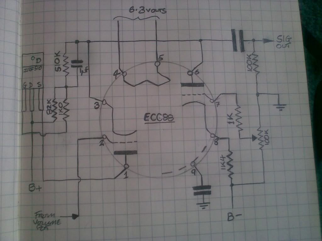
The existing volume/balance arangement is:
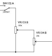
its a bit different to your 50k Pot, Do I need to adjust anything, or should it work as is? I dont think I've ever used a balance pot outside of the car, so loosing that would be no great shakes, but nice to have all the knobs doing somthing if poss.
I might use a nylon bolt to attach the FET to somthing and sleeve the legs (I ordered 5!)
[/I]
The existing volume/balance arangement is:
its a bit different to your 50k Pot, Do I need to adjust anything, or should it work as is? I dont think I've ever used a balance pot outside of the car, so loosing that would be no great shakes, but nice to have all the knobs doing somthing if poss.
One thing to pay attention to is which valve you use for top and bottom. An examination of the datasheet will indicate which one is meant to go on the bottom and which on the top.
Use your center pin as the small signal earth for the valve. The 100k cap should be a trimmer rather than a pot, multi turn is good. Other than that it all looks very good. Try to glue or tie down all the big caps, it will save on trouble when debugging/modifying later.
Your input volume pot should be OK, though probably a point for future upgrade. With this transparency of circuit it will have a very significant impact on the overall result.
Shoog
Guys,
Some points in no particular order.
The OEM power trafo is not 45-0-45. 45-0-45 is the OEM rectified value. The bipolar PSU I drew up puts things just about where the 6922 data sheet shows as "typical".
Schottky diodes are "noiseless" and don't need snubbing. Sadly, the OEM diodes are guano and noisy as the dickens.
I'm not a SLCF "maven", but a triode is a relatively poor current sink that provides a lowish dynamic load. A pentode, say 6AU6, strikes me as being better, but is the negative rail "tall" enough? Perhaps Allen Wright, originator of the SLCF, will comment in this thread.
The ECC88 is not brilliant as a current source, but its adequate, and the one used by Allen Wright himself. He makes it a bit stiffer than mine by giving the cathode 20V, rather than my 10V, but voltage is certainly limited here.
Adding a 6AU6 turns an elegantly simple little design into quite a bit more complex, and I know from experience that Allen would not approve. I say this because my latest version uses the pentode section of an ECF80 for that very purpose - and he did not approve!
The only reason I suggested not changing the rectifiers was that they could be saved with a little bit of remediation. If they are to be changed all the better. I see that I assumed that the transformer was 45VCT, my bad mistake. You can either build El Duttmans modified power supply, or you can stick with the power supply you have and just run with +/-45V rails.This places the ECC88 at the lower limits of operability, but there are designs out there such as the Musical Fidelity X10D which have very successfully run the ECC88 down at 24V. I started out using the ECC88 down at 45V in a simple cathode follower buffer and it worked. The Joe Rasmussen SLCF buffer that I orginally linked to uses the same +/-45V rails as the gainclone. So the principle is sound and proven. Running them as such low voltages eventually can lead to the grids drawing a bit more current than usual, which means they need replacing - but my Musical Fidelity X10D used the same valves for 5yrs of nearly constant on time.
Shoog
Last edited:
Well, I've been thinking I'd build Shoogs simple circuit using the +/-45v rails and when thats running look at modding the PSU to get more voltage. I'm getting the donor amp tomorrow so i'll see what voltage the rails actually are soon.
RE: "One thing to pay attention to is which valve you use for top and bottom"
From the data sheet:
 which dosen't exactly fit with this circuit, but I guess a, g, k should be top and a', g', k' should be bottom, (please let me know if I have this right) which means i have my connection diagram the wrong way around. whats the difference anyway?
I was going to use a 22 turn cermet for the 100k trim on the CSS.
RE: "One thing to pay attention to is which valve you use for top and bottom"
From the data sheet:
I was going to use a 22 turn cermet for the 100k trim on the CSS.
Yes your interpretation of the datasheet is correct. It shouldn't make to much of a difference at these voltages, but if you upgrade the power supply in the future you will want to get it right.
35V is fairly marginal when looking at the datasheet. Expect a bit of grid current. Also getting it to pass 7mA at these voltages will make it worse. Therefore I recommend running it at 4mA initially (5.6V at point A).
If you can drag +/-70V things will improve greatly - so anticipate using a different transformer or migrating to El Duttmans power supply.
Don't sweat it - you have made a decision to build one of the best designs available and it will all be worth it in the end.
Shoog
As the original designer of the SLCF circuit, I must comment:
1/ The use of MOSFETs in the circuit is unacceptable to me - in it's original design, the FVP-5 used MOSFETs for the CCS and the upper bootsrap elements - but once we had redesigned it to all tubes (FVP-5A) it sounded FAR FAR better.
2/ A CF by itself sounds ugly, I call it "Miss Piggy" in the TubePreamp CookBook. A CF with a CCS in the cathode circuit is greatly improved, but still not transparent. Adding the upper bootstrap circuit makes a wonderful sonic improvement - if you use a tube. Using a MOSFET is unpleasant, even if transparent.
3/ The JLTi buffer that uses a bipolar for the y=upper bootstrap sounds far nicer than a MOSFET, but cannot help with values, as Joe Rassmussen designed that particular varient, not me.
4/ The bipolar doesn't need much voltage to operate, so would be my suggestion for a SLCF running on low rails.
5/ But personally, I would be inclined to lift the traffo's CT, earth one end and use a voltage doubler to get a decent single voltage to run the tubes as they are designed to be run. I guess around 250V+ could be found this way, which is pretty much perfect for the full tube SLCF, as the current production SVP-2 uses only a tad more with a 265V B+ rail.
Regards, Allen
Shoog, I was re-reading somthing you said in an earlier response
What did you mean by that? Pin 9 is the screen and the ctr tap of the heater is that the pin your refering to?
Use your center pin as the small signal earth for the valve.
Shoog
What did you mean by that? Pin 9 is the screen and the ctr tap of the heater is that the pin your refering to?
>>>So why would a BJT work so much better than a MOSFET in this application? I've never really understood their relative merits.<<<
I have no theoretical idea. The thought is the non linear gate capacitance of the MOSFET is the problem. I dunno - I just know that MOSFETs no longer have any place in a vacuum State signal path.
Regards, Allen
I have no theoretical idea. The thought is the non linear gate capacitance of the MOSFET is the problem. I dunno - I just know that MOSFETs no longer have any place in a vacuum State signal path.
Regards, Allen
Shoog, I was re-reading somthing you said in an earlier response
What did you mean by that? Pin 9 is the screen and the ctr tap of the heater is that the pin your refering to?
The centre pin is the one which is unused and situated in the middle of the valve socket. It is generally used as a secure earth point for the valve.
Shoog
The centre pin is the one which is unused and situated in the middle of the valve socket. It is generally used as a secure earth point for the valve.
Shoog
I may be been dumb, but what is the "small signal earth"? do you mean what I know as the "clean earth" i.e not chasis dirty earth.
>>>So why would a BJT work so much better than a MOSFET in this application? I've never really understood their relative merits.<<<
I have no theoretical idea. The thought is the non linear gate capacitance of the MOSFET is the problem. I dunno - I just know that MOSFETs no longer have any place in a vacuum State signal path.
Regards, Allen
Ok, I shan't ignore your comments Allen, I think I'll plow on with the MOSFET for now and think about modding it to BJT later; I suppose that way I could also see if I can hear a difference!
- Status
- This old topic is closed. If you want to reopen this topic, contact a moderator using the "Report Post" button.
- Home
- Amplifiers
- Tubes / Valves
- Low Voltage Tube Preamplifier