Comparing both sounds
First. This is not a formal listening session with differents people, etc.. Just my own humble opinion. My listening setup is not that great to start with. It is in my workshop and it is used for testing and casual listening when doing project/computer work... This DAC will go in my still to come listening/home theater room, next door. I will do this room next winter. I wanted also a solid state section so I can compare it to the tube. Take it like a learning exercise as much as pure musical reproduction experiment.
The OpAmp section was also like a first try to produce a OpAmp preamp section. I'm very please with the result. I may try to build a Classe DR6 Preamp Clone in a near futur and I wanted to experiment with cap type, power suplly desing, etc...
But since I'm building for my self, I can do want I want...
I plan to compare them tonight. I was running the OpAmp completly separate to prevent any interference between them. I will run them both side by side tonight.
My first impression tell me that I will probably like them both. The tube section seems more soft, relax. It is great with classic and jazz music. It is maybe lacking solid state accuracy, crispness... It can change with an other tube brand, but I won't spend 200$ a cryo NOS type for now
But for some recording, like most pop, rock, I will probably prefer the OpAmp section.
So on a day to day basis I'm pretty sure I will use both depending on the CD.
My wife confirmed my impressions. We like the music that we hear from both sections. That a good start...
Re: PLL Locked DC voltage
Hi Algar
I am splattered by the amount of work you show us
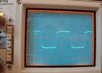
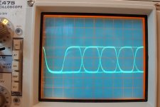
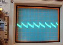
A note: The sound output is an unfiltered version of a phase comperator. The signal driving the VCXO is also derived from a phase comperator (a second one) but heavilly filtered and virtually clean.
Algar, if you listen to the signal shown, what do you hear ? It may stem from the transport jitter, and you may locate the source using the sound output that way
looking forward to your next episode
Guido
Algar_emi said:Here the DC voltage small variation on the PLL DC Signal once the PLL is locked. It is also what is called PLL Sound output on this DAC.
Hi Algar
I am splattered by the amount of work you show us
A note: The sound output is an unfiltered version of a phase comperator. The signal driving the VCXO is also derived from a phase comperator (a second one) but heavilly filtered and virtually clean.
Algar, if you listen to the signal shown, what do you hear ? It may stem from the transport jitter, and you may locate the source using the sound output that way
looking forward to your next episode
Guido
Re: PLL Sound
Hi Algar,
OK, understood. By the way, if you like the opamp based linstage, you may like the Svetlana 6N1P in the tube stage. Give it a try, they are cheap. Change cathode R's to about 100 ohm instead of original 330
regards
Algar_emi said:Still trying to find the time to do it. I plan to use my headphone amp to listen to it. I'll try to do it tonight, ouf...
Hi Algar,
OK, understood. By the way, if you like the opamp based linstage, you may like the Svetlana 6N1P in the tube stage. Give it a try, they are cheap. Change cathode R's to about 100 ohm instead of original 330
regards
hi,
Ah, finally someone did some math on that...
Cheers,
you may like the Svetlana 6N1P in the tube stage. Give it a try, they are cheap. Change cathode R's to about 100 ohm instead of original 330
Ah, finally someone did some math on that...
Cheers,
DIY Good digital cable
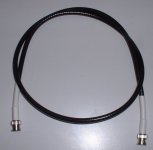
For my DAC, I built a good quality true 75 ohms cable to connect the SPDIF signal.
Description:Cable Belden 9116 RG6 Precision Coax with 2 Connectors Amphenol BNC 75 ohms, 31-70000, for RG6, crimp. RG6 offer lower attenuation compare to RG59 cable.
On the DAC and transport I planned to use real 75 ohms bulkhead connector Amphenol 31-220N-75RFX.
This will insure perfect 75 ohms transmission line between transport and DAC. I will post a picture soon...

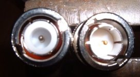
50 to 75 ohms connectors
Some reuqested picture showing the difference between the 50 to the real 75 ohms bnc connector.
On the left the normal 50 ohms, on the right the Amphenol real 75 ohms connector. That is the one I'm using on my cable and the transport/Dac.
Some reuqested picture showing the difference between the 50 to the real 75 ohms bnc connector.
On the left the normal 50 ohms, on the right the Amphenol real 75 ohms connector. That is the one I'm using on my cable and the transport/Dac.
Attachments
Re: OpAmp Back
Hi Algar_emi,
My goodness.....Here it really pays off to learn and use a simple PCB design software program and make a nice and tidy board...
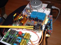
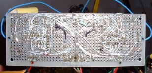
Algar_emi said:As requested, my point to point work...
Hi Algar_emi,
My goodness.....Here it really pays off to learn and use a simple PCB design software program and make a nice and tidy board...
Pcb
Yes I know. But I like doing it. It is like a hobby for me. I did a lot of PCB in the past (RF, digital, analog...) but there is a lot of limitation for prototype like most of my stuff.
For example, a star ground is a lot more demanding to implement on PCB. Second I usually do modifications on original circuit and try thing. PCB get really messy if you start to modifiy them a lot. Point to point are a snap. The circuit you saw look a little bit congested. But most of the connection are parts to parts with no wires. Capacitance are close to nothing. I used OFC copper, silver coated TFE insulated wire, much better than a 1-2oz copper pcb.
Most of the wires are used only for supply and star ground. All supply lines go directly to one point only, the regulator output.
The last reason also is that this board is quite small and would need to be much larger with a PCB. Also don't forget that this PCB purpose is for testing different OpAmp sound. There is two sockets in parallel here per channel for just one OpAmp. Because the opa604 and 627 are DIP and the AD825 (or other) is surface mount. I use a smal daugther board to connect the AD825 to a 8 pins in-line socket. That is explaining half the wires you see there...
One of my first test equipment that I've done is a good multifunction frequency counter with 1.2Ghz prescaler. I desing it completly and it was done entirely using this ptp technic. I did a lot of modif on it and it is still working without a glitch for the las 15 years
N.B. Only the RF prescaler was done using a PCB.
Finally I always do only one circuit, so no need to repeat it which PCB are good at...
Bye...
- Status
- This old topic is closed. If you want to reopen this topic, contact a moderator using the "Report Post" button.
- Home
- Source & Line
- Digital Source
- I started my new Tube DAC