SPDIF and DAC CLOCK signals and news
I measured the SPDIF and the Clock signal of my new DAC using my trusty Tek Scope. The signal are very nice indicating no measurable jitter.
I also check the square wave, 1 kHz and 1K, 20Khz sinus. The square wave is almost perfect with slight ringing on top (typical of CD output). The sinus are perfect!
I will post pictures soon.
I'm working on an op-amp line stage output, so I will have both type of sound on my DAC. I planned to use to renowned AD825 op-amp. I will post the schematic tomorrow.
Re: SPDIF and DAC CLOCK signals and news
Hi
In average, the jitter at the SPDIF is in the ns range. This is only vissible using fast sampling scopes with a low jitter time base. Tektronix series 7000 is suitable, but I wonder if you have one at home (I use these at my work and I'd love to have one at home......)
Let me point you towards our DAC page where we included a section on making jitter audible by mixing it down to zero, see
http://members.chello.nl/~m.heijligers/DAChtml/PLL sound.htm
and the general entrance here
http://members.chello.nl/~m.heijligers/DAChtml/dactop.htm
all the best
Algar_emi said:I measured the SPDIF and the Clock signal of my new DAC using my trusty Tek Scope. The signal are very nice indicating no measurable jitter.
I also check the square wave, 1 kHz and 1K, 20Khz sinus. The square wave is almost perfect with slight ringing on top (typical of CD output). The sinus are perfect!
I will post pictures soon.
I'm working on an op-amp line stage output, so I will have both type of sound on my DAC. I planned to use to renowned AD825 op-amp. I will post the schematic tomorrow.
Hi
In average, the jitter at the SPDIF is in the ns range. This is only vissible using fast sampling scopes with a low jitter time base. Tektronix series 7000 is suitable, but I wonder if you have one at home (I use these at my work and I'd love to have one at home......)
Let me point you towards our DAC page where we included a section on making jitter audible by mixing it down to zero, see
http://members.chello.nl/~m.heijligers/DAChtml/PLL sound.htm
and the general entrance here
http://members.chello.nl/~m.heijligers/DAChtml/dactop.htm
all the best
Schematics and Bill of Material
For any person interrested to build this DAC, entirely or in part, in North America, I will post the complet schematics and Bill of materials, ajusted for the North America market. For example, I found the transfo and choke replacement from Digikey and Victoria Magnetics, all in the US.
I also produced a nice (at least I think) complete interconnect diagram that is missing from Guido Tent web Site.
Bye...
Attachments
Re: SPDIF and DAC CLOCK signals and news
I would be interested in this one")
Algar_emi said:
I'm working on an op-amp line stage output, so I will have both type of sound on my DAC. I planned to use to renowned AD825 op-amp. I will post the schematic tomorrow.
I would be interested in this one
Tube Line Stage
Hi binatang. As requested the tube line stage output schematic.
You can also check:
http://www.diyaudio.com/forums/showthread.php?s=&threadid=13873
for pictures, details and some test results....
Bye.
N.B.:
Listening session among users of this DAC recommended the 6N1P as the best tube to use instead of the ECC88 or the 6922. However to use the 6N1P you need to be sure that the tube filament transfo can supply 700ma instead of the 350ma used by the 6922. Just make sure that the transfo can supply 6.3V, 1A and you're Ok.
You also need to change the cathode resistor. It can be done by adding a 120 ohms resistor in parallel to the existing 330. I added 2 jumpers and two 120R resistors, see diagram, so my PCB can accept both tube types.
I will post the Complete Bill of Materials tomorrow. It will include the parts for the Tube line Stage...
Bye.
Attachments
Re: Schematics and Bill of Material
Hello Algar
Neat work on the system overview !
thanks for sharing
Algar_emi said:For any person interrested to build this DAC, entirely or in part, in North America, I will post the complet schematics and Bill of materials, ajusted for the North America market. For example, I found the transfo and choke replacement from Digikey and Victoria Magnetics, all in the US.
I also produced a nice (at least I think) complete interconnect diagram that is missing from Guido Tent web Site.
Bye...
Hello Algar
Neat work on the system overview !
thanks for sharing
DAC Parts List
Thanks Guido. I'm glad you like it. It's me that thanks you for sharing your great desing with us. Even better were your articles on all the desing choices and tech info on all aspects of the DAC. Great work.
The complete Bill of Materials with the latest modif and small changes...
Thanks Guido. I'm glad you like it. It's me that thanks you for sharing your great desing with us. Even better were your articles on all the desing choices and tech info on all aspects of the DAC. Great work.
The complete Bill of Materials with the latest modif and small changes...
Attachments
DAC Schematics, parts 1 to 3
These schematic covert in details the DAC PCB. You can see a small modification on page 1-3 to the original PCB as recommended by Guido's team. Q11 and R4 are used to reset U2 when there is no SPDIF signal. This prevents any noise. The mute fonction of U2 doesn't seem to be reliable in all cases.
These schematic covert in details the DAC PCB. You can see a small modification on page 1-3 to the original PCB as recommended by Guido's team. Q11 and R4 are used to reset U2 when there is no SPDIF signal. This prevents any noise. The mute fonction of U2 doesn't seem to be reliable in all cases.
Attachments
First Version OpAmp Line Stage
Here my first version of the Op-Amp Line Stage. The actual desing can accept 3 differents Op-Amp the OPA604, the much more expensive OPA637 and the AD825. Just change J1-J2 according to the table to change the offset adjustement.
The OPA serie amp are in DIP format and can plug in the 8pins DIP socket. The AD825 is surface mount and will be installed on a small daughter PCB and plug on a line socket. I will post pictures. I will use this flexibility to change the amps easily and compare their sound...
Any suggestions are welcome.
N.B. This line stage will use the Low Voltage Supply AUX output, see LV_Supply schematic. You can use a good +/-15V supply instead.
Attachments
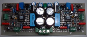
OpAmp Line Stage Completed
Here a picture of my Op-Amp Line Stage completed. I made a few change to my version 1.
Added a 100K input resistor to prevent OpAmp floating input.
Change OpAmp gain to compensate for the attenuation of the emitter follower following stage. Total gain 20.
I made a rather complex little supply running on the +/-26V of the AUX supply of my DAC.
Attachments
Ver 1.1 Schematic
To continu on the circuit description.
Lower noise LM317/LM337 regulators with Visay solid aluminium low ESR caps.
Panasonic FC caps.
Wima and Ero Film polyester and polyprolylene bypass caps.
Can accept OPA604, OPA627, AD825 opamps.
Point to Point assembly.
Star Ground
Central Power supply to reduce connexion lenght
Bourn 10T pot selectable DC offset adjustment
Metal film 1% resistors.
Green led power indicator.
Measurements will follow...
Note: The part numbers are not final...
Attachments
OpAmp Listening Session
I'm really happy with my OpAmp Line Stage. Nice soundstage, high not agressive, good bass, voices are nice also. I listen to Garry Willis, Sting, Flower Kings, Diana Krall, Steely Dan and Stereophile Test CD2. All great!
The AD825 was a real winner over the OPA604. I don't have the OPA627 to compare yet.
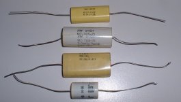
I have to use a coupling cap at the output. The circuit produces -4.45V dc at the output. So I had also the chance to compare 4 coupling caps type that I bought at a surplus store.
They all seems to be film caps from 3uF to 5uF.
Here also, a real winner, the top one on the picture, marked BEC-9613, 4uF +/-10%, 200V. Sound is great with it.
Final schematic will follow...
I'm really happy with my OpAmp Line Stage. Nice soundstage, high not agressive, good bass, voices are nice also. I listen to Garry Willis, Sting, Flower Kings, Diana Krall, Steely Dan and Stereophile Test CD2. All great!
The AD825 was a real winner over the OPA604. I don't have the OPA627 to compare yet.
I have to use a coupling cap at the output. The circuit produces -4.45V dc at the output. So I had also the chance to compare 4 coupling caps type that I bought at a surplus store.
They all seems to be film caps from 3uF to 5uF.
Here also, a real winner, the top one on the picture, marked BEC-9613, 4uF +/-10%, 200V. Sound is great with it.
Final schematic will follow...
Attachments
- Status
- This old topic is closed. If you want to reopen this topic, contact a moderator using the "Report Post" button.
- Home
- Source & Line
- Digital Source
- I started my new Tube DAC