OK.
Power supply is re-laid.
Dimensions are now 176mm x 154mm.
Phew!!!
Caters for 25mm standard and 30mm snap in Caps.
Yes,it does look great! I like the shorter board, leaves room for transformer.
Rush
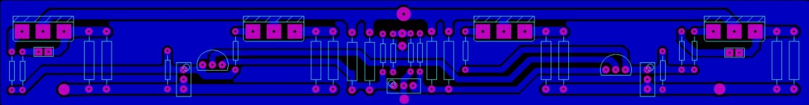
OK Power Supply done (again).
Starting to look quite complex now with the bypass caps on.
Unless there is a glaring ommision (is there?) I'll consider these as final.
Starting to look quite complex now with the bypass caps on.
Unless there is a glaring ommision (is there?) I'll consider these as final.
An externally hosted image should be here but it was not working when we last tested it.


OK Power Supply done (again).
Starting to look quite complex now with the bypass caps on.
Unless there is a glaring ommision (is there?) I'll consider these as final.
I thought one bypass cap per rail was good enough. I've never seen so many laid out like that before. But that's only my observation.
Thanks for all the good work!
... I'll consider these as final.
If you move the C4 to R1-7 track to the top of the resistors, that leaves a clear path to from the bottom of R1-7 to C10.
Another minor change I would make is to sum all the 0V tracks at the output connection.
done (again)
Mind if i ask why the 16 caps ?
Mind if i ask why the 16 caps ?
Jacco,
Have you not read the F5 Turbo pdf?
It was specified by Nelson.
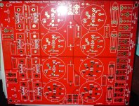
Hi everyone
here is mine pcb for V1
its so simple and clear but need some tweak ı think,ı will so
ı'll appreciate ıf someone will comment
keep in touch to f5 tuRBO
Why not put the diodes in so it can be used as version 1 or 2?
Jacco,
Obviously there are 'many ways to skin a cat'.
More experienced builders like yourself will most likely utilise there own interpretation of the PSU and probably even lay out the boards yourselves.
What I've attempted to do is try and keep as true to Papa's schematics but allow for some additional options that have been requested.
Regards
Andy
read the pdf ?
Me still have my own cerebellum.
A +40in2 power supply board is expensive.
Pap's example is interesting only for the 25mm diameter x 50mm high Panasonic TS-UP 10,000uF/50V.
If the idea is to make the board more general, more efficient would be to go for 8 electrolytics and 35 to 40mm footprint.
Example :
P-A's power supply board, can hold 448,000uF total (8 x 56,000uF) , both in TS-HA (35V) or T-UP (50V).
Few inches longer than your board, but has more gadgets, e.g. dual rectifier bridges (good thing me have huge number of stinkin diodes
 )
)Same story as with the 7 Panasonic 0R47, cost $1.75 per batch (if bought 50 minimum)
A single chassis-mount Bourns PWR221T or Vishay LTO-30 costs a buck more, the 3in2 saved on a board does more than $1.
Attachments
Last edited:
- Status
- This old topic is closed. If you want to reopen this topic, contact a moderator using the "Report Post" button.
- Home
- Amplifiers
- Pass Labs
- F5 Turbo Circuit Boards