I do not understand. There is only 1 star ground and it is not on the pcb.make your only star ground in one place - you can't have two ( as shown - one on each pcb)
let's say - make it on either PSU pcb or on input jack
if needed - put fat wire bridge between two main GND points of two amp pcbs
I think I did not make clear that in the drawing there are 2 wires leaving the star ground, 1 for each PCB.
Last edited:
Hi guys,
I am afraid I need your help again
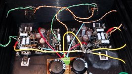
Assuming the hum was caused by a grounding problem, I decided to rewire the amp. See attached photo.
I removed the NYS2203 1/4" jacks and installed NYS216. The NYS216 is isolated (I checked with a DMM to confirm there is no connection between chassis and signal ground on the installed NYS216).
NYS2203 - REAN Connectors
NYS216 - REAN Connectors
I also replaced the input and output wiring, using twisted pairs stripped from Cat6 cable.
I changed the signalground wiring and made a new star point. The star point sits on top of a plastic hex spacer, so there is no unwanted chassis connection.
4 yellow wires meet at the star point. These 4 wires go to (clockwise on photo):
- left PCB at point marked CGND
- PSU 0
- right PCB at point marked CGND
- CL-60 (the other leg of the CL-60 is attached to the chassis)
This setup also gives me a "fat" connection between the two ground points of both pcb's, as suggested earlier by Zen Mod.
I had hoped these changes would have solved the problem, but the hum is still there.
Could the PSU be causing the hum?
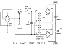
I am using 2 CDE SLPX 10000uF 35V caps and a 0R47 3W Panasonic resistor in a each CRC rail. I used 4 generic 1N4002 diodes to make a bridge rectifier.
SLPX103M035C7P3 Cornell Dubilier - CDE | Mouser
Any suggestions are appreciated.
Thanks,
Albert
I am afraid I need your help again
Assuming the hum was caused by a grounding problem, I decided to rewire the amp. See attached photo.
I removed the NYS2203 1/4" jacks and installed NYS216. The NYS216 is isolated (I checked with a DMM to confirm there is no connection between chassis and signal ground on the installed NYS216).
NYS2203 - REAN Connectors
NYS216 - REAN Connectors
I also replaced the input and output wiring, using twisted pairs stripped from Cat6 cable.
I changed the signalground wiring and made a new star point. The star point sits on top of a plastic hex spacer, so there is no unwanted chassis connection.
4 yellow wires meet at the star point. These 4 wires go to (clockwise on photo):
- left PCB at point marked CGND
- PSU 0
- right PCB at point marked CGND
- CL-60 (the other leg of the CL-60 is attached to the chassis)
This setup also gives me a "fat" connection between the two ground points of both pcb's, as suggested earlier by Zen Mod.
I had hoped these changes would have solved the problem, but the hum is still there.
Could the PSU be causing the hum?
I am using 2 CDE SLPX 10000uF 35V caps and a 0R47 3W Panasonic resistor in a each CRC rail. I used 4 generic 1N4002 diodes to make a bridge rectifier.
SLPX103M035C7P3 Cornell Dubilier - CDE | Mouser
Any suggestions are appreciated.
Thanks,
Albert
Attachments
Last edited:
Hi Zen Mod,
Thanks for your quick reply.
I checked the specs and they should be OK for parallel operation. I used Amplimo 18612:
2x 12V ringkerntransformator 30VA
http://www.amplimo.nl/images/downloads/ds standardrange/18612.pdf
Could the diodes be the cause of the hum?
Or the 40mV DC offset at the output (measured with inputs grounded after 30min warmup)?
Thanks,
Albert
Thanks for your quick reply.
just thinking ..... maybe xformers aren't intended for parallel operation of secondaries ?
I checked the specs and they should be OK for parallel operation. I used Amplimo 18612:
2x 12V ringkerntransformator 30VA
http://www.amplimo.nl/images/downloads/ds standardrange/18612.pdf
I have thought of that, but wanted to get rid of the hum first before deciding. Also I was worried about a possible ground loop because signalground of both channels are connected at the input and output 1/4" jacks.why don't you make proper dual mono PSU/configuration , having 10mF per rail , for each channel ?
in that case , also having one CL60 between each channel's audio gnd and case
Could the diodes be the cause of the hum?
Or the 40mV DC offset at the output (measured with inputs grounded after 30min warmup)?
Thanks,
Albert
If the aforementioned helps, you can then simply disconnect the white wires from the input and output connectors (leave the pcb side attached) and run another yellow wire from the connectors' ground tab to the star ground, which will only then be a proper start ground.
Y'all have no idea how much I hate ground loops...
Y'all have no idea how much I hate ground loops...
Assuming the white cat5 wire is ground, you are forming a formidable ground loop through the inputs, outputs and yellow ground wires.
Disconnect all signal carrying wires from one channel (breaking the loop). Does the remaining channel still have hum?
Hi Rodeodave,
I disconnected the left channel (all wires, i.e. blue V-, red V+, yellow GND, orange + white from input and orange + white from output). Hum is still there.
Tried the same for the other channel (i.e. removed all connections to right channel PCB) bit it also has hum (actually a bit more than the other).
I have been thinking and am wondering if an incorrect match of the input IRF9610's could be the cause. I bought matched fets from a German supplier through ebay, but perhaps they were not so well matched as I had expected.
The chipamp board does not have room for a trimpot, but after studying the Aleph J schematic http://www.diyaudio.com/forums/atta...eph-j-universal-mounting-spec-aj-skema-bw.png I think I need to replace the 392R resistor (R14 in Metalman's schematic; R18 on the PCB) by a trimpot. Any idea if that could help or should I concentrate on the PSU?
Thanks,
Albert
Hi Zen Mod (and others of course),
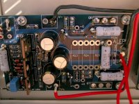
I had a small PSU board that I had made sometime earlier. It is the unregulated PSU as described by Wayne in the Pearl 2 article (see schematic below).
https://www.passdiy.com/project/preamplifiers/pearl-2
Each rail has 4 x 1N400x diodes (as bridge rectifiers), 1 x Nichion 10000uF 35V cap and a 3W 2k2 bleeder resistor. I know it will have a larger ripple than the PSU I had used so far (this Pearl 2 PSU is unregulated; the Pearl 2 regulates the supply on the preamp pcb), but it was interesting to see what it would do in my Aleph H. Would it affect the hum I had been getting?
I hooked it up to the 2 Amplimo toroids and yes, it did affect the hum. The hum got worse!
Note: this was with only 1 channel connected (input shorted) so not due to ground loops due to shared signal ground of both channels.
Can I generalise and say that in a given circuit, all other things being equal, hum or noise is proportional to ripple current?
I am a bit surprised that I am having this much trouble with what I expected to be a straightforward build, so decided to spend a few hours reading older posts. This is after all a great opportunity to learn!
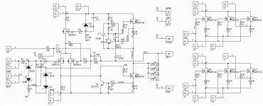
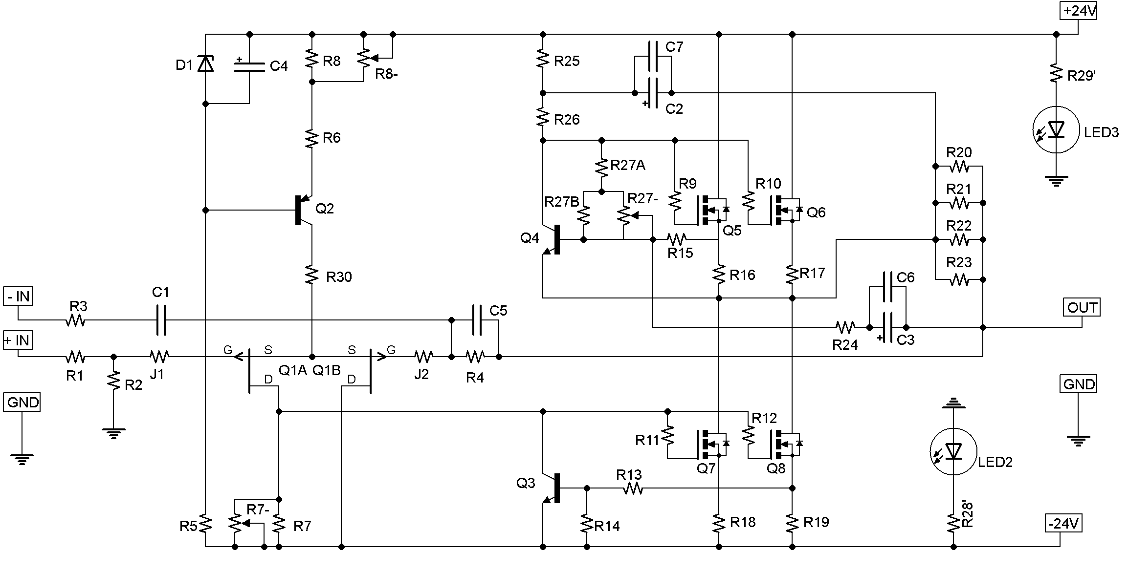
After re-reading the posts and the 6 moons article, there are a few things that I do not understand. Could it be that the schematic that Metalman posted in post#1 is wrong? I will try to explain why I am unsure if the schematic is correct.
But, the schematic does not fit the photo's or what is mentioned in the article!
1.
As Zen Mod mentioned in post #5, the amp discussed in the 6 moons article was unity gain. The schematic has 10V/V gain.
2.
The photo's in the article show a 50VA toroid. Zen Mod explained in post #55 when I asked if a 2x12VAC 30VA toroid was adequate:
But in the article Metalman is quoted saying:
Parts used.
- C4 (chipamp board numbering; across 100k resistor R15 (chipamp numbering)/R7 (Metalman numbering)) and
- C6 (chipamp board numbering; across Z5 zener).
These are not included in the schematic in post #1.
4.
As I mentioned in post #59, the photo's of the 6 moons article show only 1 3W 0R47 installed, but Metalman's schematic shows 2.
(R25/26 Metalman's numbering; R23-26 chipamp numbering).
I have no idea how good the general Aleph design is with regard to ripple rejection or otherwise if it tolerates a PSU that is so-so. I know that my DIY Aleph J (Peter Daniels boards, CRC PSU using 33000uF 50V Nippon Chemi, 4 x 0R47 3W Panasonic, 33000uF 50V Nippon Chemi) is dead quiet.
Could someone who can actually understand the schematic that Metalman posted in post#1 check it for any obvious errors? I am afaid I just "paint by numbers" and do not know how to proceed.
Thanks,
Albert
concentrate on psu and wiring
I had a small PSU board that I had made sometime earlier. It is the unregulated PSU as described by Wayne in the Pearl 2 article (see schematic below).
https://www.passdiy.com/project/preamplifiers/pearl-2
Each rail has 4 x 1N400x diodes (as bridge rectifiers), 1 x Nichion 10000uF 35V cap and a 3W 2k2 bleeder resistor. I know it will have a larger ripple than the PSU I had used so far (this Pearl 2 PSU is unregulated; the Pearl 2 regulates the supply on the preamp pcb), but it was interesting to see what it would do in my Aleph H. Would it affect the hum I had been getting?
I hooked it up to the 2 Amplimo toroids and yes, it did affect the hum. The hum got worse!
Note: this was with only 1 channel connected (input shorted) so not due to ground loops due to shared signal ground of both channels.
Can I generalise and say that in a given circuit, all other things being equal, hum or noise is proportional to ripple current?
I am a bit surprised that I am having this much trouble with what I expected to be a straightforward build, so decided to spend a few hours reading older posts. This is after all a great opportunity to learn!
After re-reading the posts and the 6 moons article, there are a few things that I do not understand. Could it be that the schematic that Metalman posted in post#1 is wrong? I will try to explain why I am unsure if the schematic is correct.
metalman said:Many ... many ... many moons ago, I adapted the Nelson Pass` Aleph circuit topology to build a nifty, but ridiculously overbuild headphone amplifier that I named the Aleph H. I thought it was pretty cool, and circumstances came about that presented the opportunity to have my DIY project reviewed by Srajan Ebaen of 6Moons. Turns out Srajan liked it too and gave it a very positive review.
Somehow, I just never got around to publishing the schematic here for others to use. Periodically through the years I have had pokes from diyAudio members who have read the review and want to build my version, given its reviewed and 6Moons approved status. I have always shared with those that asked, but stupidly never taken the extra few moments to post it here.
That laziness ends here!
I have finally attached the schematic for the ciruit I built.
But, the schematic does not fit the photo's or what is mentioned in the article!
1.
As Zen Mod mentioned in post #5, the amp discussed in the 6 moons article was unity gain. The schematic has 10V/V gain.
2.
The photo's in the article show a 50VA toroid. Zen Mod explained in post #55 when I asked if a 2x12VAC 30VA toroid was adequate:
Zen Mod said:lazy to explain voltage divider in base of upper ZTX , but say that Iq is aroundish 400mA
so , 2x 15Vdc x 0A4 =12VA/channel
45VA xformer minimum
But in the article Metalman is quoted saying:
3.I used a transformer rated at several times the power requirement of the amp.
Parts used.
The photo in the article shows the mica and film caps installed atThe capacitors are Panasonic electrolytic and polypropylene film types with the exception of a single silver-mica cap per channel.
- C4 (chipamp board numbering; across 100k resistor R15 (chipamp numbering)/R7 (Metalman numbering)) and
- C6 (chipamp board numbering; across Z5 zener).
These are not included in the schematic in post #1.
4.
As I mentioned in post #59, the photo's of the 6 moons article show only 1 3W 0R47 installed, but Metalman's schematic shows 2.
(R25/26 Metalman's numbering; R23-26 chipamp numbering).
I have no idea how good the general Aleph design is with regard to ripple rejection or otherwise if it tolerates a PSU that is so-so. I know that my DIY Aleph J (Peter Daniels boards, CRC PSU using 33000uF 50V Nippon Chemi, 4 x 0R47 3W Panasonic, 33000uF 50V Nippon Chemi) is dead quiet.
Could someone who can actually understand the schematic that Metalman posted in post#1 check it for any obvious errors? I am afaid I just "paint by numbers" and do not know how to proceed.
Thanks,
Albert
Attachments
Do your output mosfet bolted to the chassis have a insulating shoulder washer in them? To keep the screw from making an electrical connection from the metal tab to the chassis?
More importantly, detach all the Cat5 ground wires from their current locations on the PCB and attach all to the star. (Yes, it will still work.)
More importantly, detach all the Cat5 ground wires from their current locations on the PCB and attach all to the star. (Yes, it will still work.)
Last edited:
Hi guys,
Thanks for your replies and suggestions. I have rewired the amp and reinstalled the original CRC psu.
wiring as follows:
both pcbs:
Red from V+ to psu+
Blue from V- to psu-
Yellow from GND to stargnd
Single cat6 wire from UIN to input jack
Single cat6 wire from OUT to output jack
ground from input jack to stargnd
ground from output jack to stargnd
Psu 0 to stargnd
stargnd via cl-60 to chassis
I checked the 610's and they are isolated (no continuity between 610 metal and screw).
hum remains ...
It is not so bad that you can't hear the music but is very annoying, specially during soft passages (classical music).
I think I can be reasonably sure that wiring is not the issue. Psu is my next guess. After 10 min or so I had 61mV of ripple (under load as amp was connected).
Perhaps a dial mono using 7812/7912 would be an idea. I think I have some 78xx and 79xx in a drawer somewhere that I bought from a surplus shop but have never used.
I think it would be good to have a decent reference power supply and think I will buy a bench power supply. Any suggestions for a good bench power supply are appreciated.
Would a (relatively cheap) Rigol digital scope help to find the cause of these kind of problems? Any other suggestions?
Thanks,
Albert
C5 can help quelch (suppress) oscillations. Can't hurt to try if you have a 1nF cap around.
Thanks Rodeodave.
I may have a ceramic (have to check a set of cheap chinese I bought but never used). Is it suitable or should it be film or mica?
Is the hum getting any better/different with the wiring changes?
Don't worry about regulators, just add capacitance. Before the resistor.
Would like to see another photo of the new wiring...")
Hi 6L6,
Wiring changes did not really make any difference.
Will try to upload a photo
Albert
- Home
- Amplifiers
- Pass Labs
- Aleph H Schematic - Revealed at Last