Thanks!
Interesting thread! I missed it completely
Are you suggesting using the PCB for the aleph h och going for the Babelfish j? The I had a quick look and I think the PCB needs some small tweaks to mach the aleph h design. I also found some pointers for the Babelfish as a headamp that could be interesting if i could source the parts....
B.R Christian
MiniAleph to Aleph H modification
Hi, my MiniAleph has been sitting on a shelve now for some time collecting dust, so when I came across the Aleph H I immediately thought of doing a conversion. And while I'm at it I might as well do some modifications.
My Mini-A very closely resembles Grey Rollins' original version (see 2nd attachment). The only mods I've made were the addition of protection Zeners, a 10pF cap over the feedback resistor, a pot to set the Aleph CS's gain and a 1nF cap in the Aleph CS.
Now the first circuit I've attached shows the circuit I have in mind, and of course I have some questions. I'm using the same part numbers as in Grey's schematic.
Well, that's all I can think of, for now...
Hi, my MiniAleph has been sitting on a shelve now for some time collecting dust, so when I came across the Aleph H I immediately thought of doing a conversion. And while I'm at it I might as well do some modifications.
My Mini-A very closely resembles Grey Rollins' original version (see 2nd attachment). The only mods I've made were the addition of protection Zeners, a 10pF cap over the feedback resistor, a pot to set the Aleph CS's gain and a 1nF cap in the Aleph CS.
Now the first circuit I've attached shows the circuit I have in mind, and of course I have some questions. I'm using the same part numbers as in Grey's schematic.
- The voltage gain, afaik, is given by V_out=V_in*(1+R8/R6). In the original design the factor is (1+10k/1k)=11 (20.8dB of gain) if I'm not mistaken, and with R6=10k it should come out as 2 (6dB of gain). Will the simple mod of swapping the current 1k resistor (as per Grey's Mini-A schematic) for a 10k resistor do the conversion from Mini-A to Aleph H?
- The original design sets the gate of the CCS-FET of the input differential at V_supply-9.1V (because of the 9.1V Zener), which comes out to about 5.9V. I'd like to switch to a LED&JFET based voltage reference, made up of a 2SK170 and three LEDs. How critical is the voltage here, and how would I go about determining the sweetspot?
- Should I leave the protection Zeners in place?
Well, that's all I can think of, for now...
Attachments

Hi, my MiniAleph has been sitting on a shelve now for some time collecting dust, so when I came across the Aleph H I immediately thought of doing a conversion. And while I'm at it I might as well do some modifications.
Sorry, but I am going to hi-jack this thread for a moment.
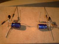
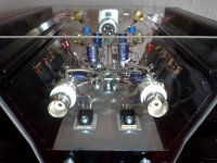
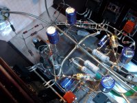
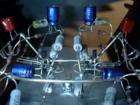
That is your Mini-A?
 Just leave it because that is a piece of art in terms of dead bug construction. I have seen some nice executions, but this is up there in terms of looks and balance.
Hello Rodeodave,
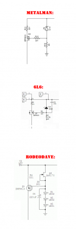
I worry that your schematic diagram may contain a mistake. The current source for the differential amplifier ("Q1" in your schematic), includes a voltage reference generator made from zener diodes. Metalman's schematic (post #1 in this thread) and 6L6's schematic (post #14) also include a voltage reference generator made from zener diodes.
However, their references are connected between the PMOS's gate and positive supply, thereby placing a constant voltage (Vref - V_pmos_threshold) across the source resistor ("R4" in your schematic), thereby achieving a constant current in R4. A constant current source.
On the other hand, your schematic connects the zener diode reference between the PMOS's gate and ground. So the voltage across your R4 equals (Vsupply - V_pmos_threshold - Vref) and that's very bad news, because now the current in R4 fluctuates when Vsupply fluctuates.
Maybe this is just a mistake on the drawings, and not a design error?
Attachments
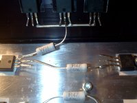
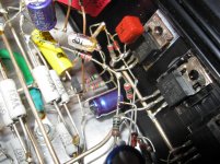
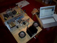
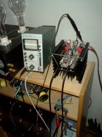
It indeed is my Mini-Aleph I used to power Fostex FE108EZ backloaded horns with it, very sweet sound. I attached some more pics.
And the idea behind the JFET&LED variant is to use the LEDs' band gaps as a voltage reference. To do this you run the JFET as a constant current source by tying the gate to source potential, thereby constantly running it at I_DSS (about 8mA in the present case), and having a fixed and steady voltage develop by pushing that current through a chain of LEDs that will each drop a fixed voltage that's depending on their intrinsic band gap.
I used to power Fostex FE108EZ backloaded horns with it, very sweet sound. I attached some more pics.And the idea behind the JFET&LED variant is to use the LEDs' band gaps as a voltage reference. To do this you run the JFET as a constant current source by tying the gate to source potential, thereby constantly running it at I_DSS (about 8mA in the present case), and having a fixed and steady voltage develop by pushing that current through a chain of LEDs that will each drop a fixed voltage that's depending on their intrinsic band gap.
Attachments
-
 P1390023.JPG535.1 KB · Views: 1,164
 -
 P1390089.JPG530.3 KB · Views: 1,041
 -
 IMG_0253.jpg884.4 KB · Views: 361
 -
 IMG_0247.jpg859.1 KB · Views: 379
 -
 050120101088.jpg641.4 KB · Views: 363
 -
 P1420025.JPG542.5 KB · Views: 367
 -
 P1430034.JPG553.4 KB · Views: 943
 -
 P1420011.JPG533.9 KB · Views: 972
 -
 P1400011.JPG537.6 KB · Views: 1,013
 -
 P1470015.JPG557 KB · Views: 385
These power MOSFETs have quite a large range of gate threshold voltage variation; the IRF644's datasheet says 2.0V to 4.0V (!).
I worry that your schematic (unlike jwb's) does not appear to include any mechanism for setting the DC bias current of your output pulldown transistor Q9. Q9's bias current varies with its gate threshold voltage; since the threshold varies a lot, so does the bias current. Yet you apply a constant, fixed, unadjustable DC bias voltage to the gate of Q9, no matter what its gate threshold voltage happens to be.
I worry that your schematic (unlike jwb's) does not appear to include any mechanism for setting the DC bias current of your output pulldown transistor Q9. Q9's bias current varies with its gate threshold voltage; since the threshold varies a lot, so does the bias current. Yet you apply a constant, fixed, unadjustable DC bias voltage to the gate of Q9, no matter what its gate threshold voltage happens to be.
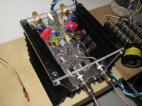
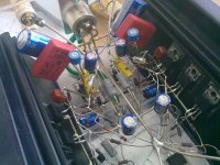
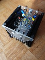
I'm starting an Aleph J-H, I have tons of extra stuff in my bin o' parts, and I've been intrigued by the Aleph headphone amp concept for quite a long time.
Same basic topology, but with the Aleph-J front end. Single FP3N30 in the CCS and as the output device, 15V rails.
A few photos of the beginnings -
The excellent Peter Daniel Aleph J PCB.
The 'big, dumb' approach works for me. If needed I may add a zen-type regulator, but only if the voltage is too high.
This is a transformer salvaged from a subwoofer plate amp, it's 24-0-24, but as it has dual primaries I'll just use them in series to make it 12V.
The little ones next to the amp PCB are Dale RN55, the blue ones on the PSU are some really fancy, 3W, teflon-wrapped 0.1% 100ppm 2.2Kohm that I am using rather un-ceremoniously as bleeders. Both are from my local surplus store.
I'm a bit further along, I need to take some photos and continue. I really need to make a decision as to what chassis I am going to use, but breadboarding will commence soon.
I'm a bit further along, I need to take some photos and continue. I really need to make a decision as to what chassis I am going to use, but breadboarding will commence soon.
Hi!
Very interesting! I'm gathering parts for a very similar 'aleph h-j' project. I have breadboarded one channel of the original circuit and it sounds grate. My main reason to go for adding the jfet input is that i want to connect i directly to my es9018 dac in voltage mode. So i need the impedance to be higher. I just need to figure out the best way to handle the 1.65v offset.
I do have a balanced set of cables to my senns and im toying with the idea to make a X version just to try it out, but I do not see the reasons why it would give me any sonic benefits.
Best Regards Christian

- Home
- Amplifiers
- Pass Labs
- Aleph H Schematic - Revealed at Last