Thanks Zen Mod.
Just one question. I think you misunderstood what I meant in question 4:
I assume that "gnd" in the schematic means signal ground. I know that signal ground and chassis ground are connected via a CL60. That was not what I meant.
In most schematics, the input goes to signal ground via a resistor, but in the chipamp there is another resistor, R0 (3W 3R). I enclose 2 schematics to show the difference. 1 is from Metalman, the other from the chipamp schematic.
What is the function of R0? Is it required?
Thanks,
Albert
Just one question. I think you misunderstood what I meant in question 4:
4.you are around long enough to learn basics - everything is connected to audio gnd , case is connected to safety gnd and there is CL60 in between audio gnd and case
I assume that "gnd" in the schematic means signal ground. I know that signal ground and chassis ground are connected via a CL60. That was not what I meant.
In most schematics, the input goes to signal ground via a resistor, but in the chipamp there is another resistor, R0 (3W 3R). I enclose 2 schematics to show the difference. 1 is from Metalman, the other from the chipamp schematic.
What is the function of R0? Is it required?
Thanks,
Albert
Attachments
those above variations are ..... variations ; my vote is for CL60 instead of R0 (left pic , non existent in right pic)
Ah, now I understand. Thanks Zen Mod.
I made a simple CRC PSU (CDE 10000uF 35V, Panasonic 0R47 3W, CDE 10000uF 35V) using 1N4002 diodes I had in my drawer. Perhaps I will change the diodes in the future as suggested by Zen Mod.
I used PSU Designer and think that with the load I expect that a single 3W 0R47 in the rails should be OK. It's simple to change if required.
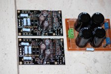
I had already bought Aleph boards from Chipamp. A German ebay seller supplied matched IRF9610 IRF9610 matched quad | eBay (he also supplied the IRF610 I will be using). The single Q3 IRF9610 came from a surplus store.
All other parts from Mouser (Dale RN55D and Panasonic 3W resistors, Silmic II caps, ZTX450).
After renumbering using the schematics provided by Metalman (post #1) and 6L6 (post #14) to fit the Chipamp boards (I hope I got it right) things were easy.
I now have to wait to get mounting holes drilled in the bottom plate before I can assemble and test.
Thanks Zen Mod, Metalman, 6L6 and of course Nelson. Hope to be able to report back in a few days.
I used PSU Designer and think that with the load I expect that a single 3W 0R47 in the rails should be OK. It's simple to change if required.
I had already bought Aleph boards from Chipamp. A German ebay seller supplied matched IRF9610 IRF9610 matched quad | eBay (he also supplied the IRF610 I will be using). The single Q3 IRF9610 came from a surplus store.
All other parts from Mouser (Dale RN55D and Panasonic 3W resistors, Silmic II caps, ZTX450).
After renumbering using the schematics provided by Metalman (post #1) and 6L6 (post #14) to fit the Chipamp boards (I hope I got it right) things were easy.
I now have to wait to get mounting holes drilled in the bottom plate before I can assemble and test.
Thanks Zen Mod, Metalman, 6L6 and of course Nelson. Hope to be able to report back in a few days.
Attachments
Last edited:
For the Aleph H I am building I have bought matched IRF610. These have a metal back and the top part (where the mounting hole is located) is also metal.
I am puzzled how to mount the IRF610 to the bottom plate of the amp (that will be its heatsink) because I assume it must be electrically isolated from the bottom plate.
The Aleph J I built some time ago had transistors with plastic casings. I mounted them to the heat sink using an aluminium bar with M3 screws on either side of the transistor (so there was no screw through the hole in the transistor) and pink kerathem between the transistor and the heatsink. Perfect electrical isolation.
I planned to use the same keratherm between IRF610 and bottom plate, but how to avoid an electrical connection? I do not plan to use a bar but a screw through each transistor. I just realised the screw will touch both bottom plate and transistor!
Should I use a plastic washer between the a screw and transistor?
Or should I use a plastic screw?
Or am I missing something obvious?
Thanks,
Albert
> Or am I missing something obvious?
Yes.
IB 2: Isolierbuchse für TO220, TOP3 bei reichelt elektronik
http://linearaudionet.solide-ict.nl/sites/linearaudio.net/files/Didden LA V3 PK lr.pdf (Photo 1)
No need to use plastic screws.
Patrick
Yes.
IB 2: Isolierbuchse für TO220, TOP3 bei reichelt elektronik
http://linearaudionet.solide-ict.nl/sites/linearaudio.net/files/Didden LA V3 PK lr.pdf (Photo 1)
No need to use plastic screws.
Patrick
Last edited:
There are isolation kits available with a plastic (usually nylon iirc) sleeve/washer for the screw, like this: http://uk.farnell.com/productimages/standard/en_GB/520214-40.jpg Just search for TO220 isolation kit on eBay/Google.
Thanks Patrick and Rodeodave.
After reading your reply I remembered that I had bought some Keystone sets long ago for a friend who was building an amp for me at the time (this was before I started my own DIY experiences). I just checked and they include the "shoulder washer" that I need.
4724 Keystone Electronics | Mouser
I never used the keystone sets, because when I built my Aleph J I used Keratherm and a bar to hold the transistors to the heatsink, so the keystone sets were lying in the drawer, forgotten ... until now.
Thanks again, let's see how far I get tonight.
Albert
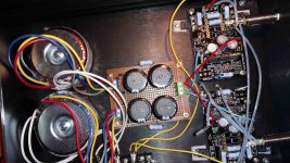
Amp is completed and working. Attached mobile phone photo (inputs grounded).
Measurements:
PSU under load (after ca. 20 min) +12.5V and -12.5V with 59mV ripple.
After 20-30 min top of Mosfet case is 40-45 C according to IR temp sensor, so it seems the bottom plate is an adequate heatsink.
Voltage drop across R29 and R35 1R resistors (Metalman's post#1 schematic) is 472mV and 468mV. I assume that current is aprox. 470mA and power consumed is 2 x 12.5 x 0.470 x 2 = 23.5W.
With inputs grounded and after ca. 30 min switched on the DC offset is about 40mV.
You can hear that it is capable of driving a Beyer DT770 (250R) properly but I can't appreciate the music because of an annoying hum. Turning the (2 x 30VA, 2 x 12VDC secondaries) toroids makes no difference. Is the hum caused by DC on the outputs? If so, how to reduce DC offset?
I have not yet installed an X2 capacitor across the 230V AC. Will figure out a nice (and safe) way of installing it tomorrow to see if that makes a difference.
Always open for suggestions")
Measurements:
PSU under load (after ca. 20 min) +12.5V and -12.5V with 59mV ripple.
After 20-30 min top of Mosfet case is 40-45 C according to IR temp sensor, so it seems the bottom plate is an adequate heatsink.
Voltage drop across R29 and R35 1R resistors (Metalman's post#1 schematic) is 472mV and 468mV. I assume that current is aprox. 470mA and power consumed is 2 x 12.5 x 0.470 x 2 = 23.5W.
With inputs grounded and after ca. 30 min switched on the DC offset is about 40mV.
You can hear that it is capable of driving a Beyer DT770 (250R) properly but I can't appreciate the music because of an annoying hum. Turning the (2 x 30VA, 2 x 12VDC secondaries) toroids makes no difference. Is the hum caused by DC on the outputs? If so, how to reduce DC offset?
I have not yet installed an X2 capacitor across the 230V AC. Will figure out a nice (and safe) way of installing it tomorrow to see if that makes a difference.
Always open for suggestions
Attachments
hum without anything on inputs?
Yes. Inputs shorted as in picture, hum remains.
We'll need more detailed pics showing the complete wiring. What's up with the lose wires/connectors in the pic you posted?
Is everything (inputs, outputs, FETs) isolated from the chassis? Smooth DC offset will generally not cause hum. I'm not sure, but maybe psu filtering capacitance is too low?
Is everything (inputs, outputs, FETs) isolated from the chassis? Smooth DC offset will generally not cause hum. I'm not sure, but maybe psu filtering capacitance is too low?
Thanks for your replies.
Loose wires in pic were inputs that were disconnected in order to ground inputs using short jumper wires.
I just checked and the Neutrik 1/4" jack is not isolated. Had incorrectly assumed it would be. Everything else is isolated from chassis.
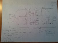
Drawing of xformers and psu attached.
Loose wires in pic were inputs that were disconnected in order to ground inputs using short jumper wires.
I just checked and the Neutrik 1/4" jack is not isolated. Had incorrectly assumed it would be. Everything else is isolated from chassis.
Drawing of xformers and psu attached.
Attachments
Realise the chassis connection of the 1/4" jacks is not ideal. Tried the following to see if I could get rid of the hum:
a.
removed front panel from enclosure and laid on top of enclosure with bubble wrap between panel and enclosure (i.e. electrically isolated).
hum remains
b.
panel as described in a.
signalground of both input and output jacks are connected to chassis, so a possible grond loop. Disconnected input signal ground connection.
hum remains
Moved star ground 3 inches to front, further away from toroids and 230V wiring. No change. Am running out of ideas. Any suggestions would be appreciated.
Wiring of PCB:
2 seperate wires (RED) from V+ PSU to V+ on PCB
2 seperate wires (BLUE) from V- PSU to V- on PCB
single wire (YELLOW) from 0 PSU to star ground and 2 seperate wires (YELLOW) from star ground to CGND on PCB
Input 1/4" jack connected to SG and UIN on both PCB's
Output 1/4" jack connected to GND and OUT on both PCB's
Because of non-isolated 1/4" jacks, front panel removed from enclosure (no longer attached so electrically isolated).
Because of possible ground loop due to shell of input and output jacks sharing the front panel, disconnected input jack wires from SG on PCB.
Thanks,
Albert
- Home
- Amplifiers
- Pass Labs
- Aleph H Schematic - Revealed at Last