pics ")
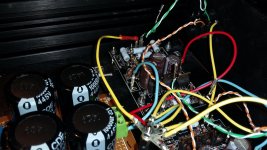
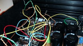
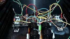
The white cat6 wires are not connected. Both ends are free and touch nothing.
same amp, 3 different views to help see how everything is connected.
The white cat6 wires are not connected. Both ends are free and touch nothing.
same amp, 3 different views to help see how everything is connected.
Attachments
Last edited:
Try the 1nF caps (C5) with what you have on hand. You can always get a nicer fkp2 or mica cap later.
Terminate the white wires at the pcb only (effectively grounding one end).
An oscilloscope may help locate the source of the hum. Since it didn't change much with one channel disconnected completely and also because changing the wiring scheme didn't do much, I would not rule out an oscillation of the circuit. What you are hearing may be a downmodulated, slower oscillation. I ran into something like that with my mini aleph build. The 1nF and local psu decoupling caps cured that. A cheap analog scope is more useful than a digital scope for audio in my opinion.
Edit: Noisy Zener diodes are also not unheard of. This could mean that one input protection Zener diodes is the source of hum. Many variables.
Last edited:
Hum is caused by the psu.
In the 6 moons paper it is mentioned that metalman used 200000uF total capacitance in the psu. I thought 40000uF would be enough but I was wrong.
I had some big (too big to fit chassis) nippon chemi 33000uF 50V caps and added them before the resistor, giving CRC of 43000uF, 0R47, 10000uF per rail. Blew the fuse (I had no cl-60 left for inrush limiting) but got it running with a 1.6A fuse.
With 1 channel connected it is now dead quiet. With both channels there is a slight hum. Ripple is about 17mV.
I have ripped out the cat6 wiring and am back to 0.5mm silver in teflon sleeves for signal. Sounds much better. The big nippon chemi caps are draining and I hope to replace them this week with some ridiculously high capacity 68000uF 16V Panasonic UP I just ordered (together with a couple of cl-60 for inrush limiting). Using 156000uF total capacitance should make this monster dead quiet!
I'll let you know how things go and post a picture of (I hope) a neater amp.
I am curious if anyone else has built the Aleph H. If so, what psu were you using?
Thanks to everyone for your help.
Albert
then it's drek caps , not amount of alleged capacitance
though ...... to be honest , I somehow forgot that you're dealing with cans , not speakers ..........
so , yes - you need either ridiculous amount of capacitance , or series regs ...... but then you need some more voltage in secondaries
though ...... to be honest , I somehow forgot that you're dealing with cans , not speakers ..........
so , yes - you need either ridiculous amount of capacitance , or series regs ...... but then you need some more voltage in secondaries
0R47 and 10000µF makes a first order low pass of 32Hz.
So ripple attenuation at 100Hz is only a factor of 3.
Increasing capacity before the RC will reduce some incoming ripple, but at the expense of much higher pulse current.
Easier to just increase R.
In the DAO, I use 10,000µF-11R-10,000µF. Corner frequency is 1.4Hz.
Total current consumption 500mA.
No hum whatsoever.
In the F5-HA I used 1000µF after standard regulators.
Also dead quiet.
And I would rather use separate CRCs for left and right channels then one big cap for both.
Patrick
Last edited:
0R47 and 10000µF makes a first order low pass of 32Hz.
So ripple attenuation at 100Hz is only a factor of 3.
Increasing capacity before the RC will reduce some incoming ripple, but at the expense of much higher pulse current.
Easier to just increase R.
In the DAO, I use 10,000µF-11R-10,000µF. Corner frequency is 1.4Hz.
Total current consumption 500mA.
No hum whatsoever.
In the F5-HA I used 1000µF after standard regulators.
Also dead quiet.
And I would rather use separate CRCs for left and right channels then one big cap for both.
Patrick
Thanks Patrick. I looked up RC filter and think I now understandwhy the amp was humming. It does help to understand the theoretical side of things
Am I correct to assume that increasing either R or C after R, but not C before R (as I had intended) will have the same effect, i.e. lowering the corner frequency?
I think I will have some nice spare 68000uF 16V caps for a new project!
I leave you a spice file to play with.
LT Spice is free to download, and easy to use.
It is about time to learn, if not already.
Feel free to change any of the component values and see how output voltage, transformer current, etc. changes.
The next thing is to try to understand why the amplifier circuit itself is so sensitive to power supply noise.
Something called Power Supply Rejection Ratio (PSRR).
Patrick
Attachments
As you may recall, my Aleph H sounded great but had an annoying hum that did no want to go away. I had previously found out that it was not caused by wiring or ground loops but rather by the PSU. I had a number of options to try to get rid of the hum:
EUVL suggested increasing the resistance in the RC filter of the CRC psu from 0R47 to 11R as this would lower the corner frequency of the RC filter to 1.4Hz. I modelled the amp as a 12R load (I had previously measured it drawing aprox. 500mA per IRF610 and was expecting about 12V DC) in PSU Designer. PSU Designer simulated about 8V across the 11R resistor, substantially overloading the 3W resistor I had planned to use.
In a dual mono setup (modelled as a 24R load) PSU Designer was still predicting >5V across the 11R resistor. Given my inexperience with the modelling tool, I realised that a small mistake in my assumptions could easily result in overloading the 11R resistor and thought it best to try something else first.
A dual mono setup using 7812/7912 regulators seemed a good idea, but my drawer contained only 7805 and 7812 regulators. No negative regulators at all. Next!
I did not want to take the easy option of using a store-bought psu. I considered a transistor regulated psu but have no experience with these circuits. Perhaps better to learn using LT Spice first before I blow up the Aleph H!
When I had previously connected a large Nippon Chemi 33000uF/50V capacitor in parallel to the first 10000uF capacitor of the 10000/0R47/10000 psu, there was a small hum when the psu was powering both channels but no detectable hum powering a single channel. Perhaps capacitance is the audio equivalent of engine displacement. If so, does "there is no substitute for cubic inches" also hold?
I had already bought a couple of 68000uF/16V capacitors, so spent some time with PSU designer and decided to go for a shared CRC psu with overkill specs: 68000uF/2R2/68000uF!
Using the RC filter equation, this setup gives me a corner frequency of just over 1Hz. With a predicted ripple of only 1.2mV, this amp should now be dead quiet!
I know, 272000uF is ridiculous for a headamp. According to the service manuals, it is more than the original Aleph 3 (8 x 22000 = 176000) used, as well as any other factory Aleph, including the large monoblocks. But this being DIY and having the parts in my drawer, it was worth a try.
Now was also a good time to change the diodes I had in the bridge rectifier from standard 1N4002 to Schottky types, as recommended by Zen Mod.
The PSU I ended up with consists of 2 rails, each made up of:
I realise that there are far better ways to tame the beast, but I did end up with a quiet headamp and a now have a very nice test amp to start experimenting with PSU design. I still do not know why this amp is so susceptible to PSU noise but hope to find out in the future when I start to make sense of the Aleph schematic.
Some figures of the amp (after 30min.) below. As you can see, the ripple is even smaller than predicted:
I can recommend this amp to anyone wanting to learn more about noisy power supplies!
EUVL suggested increasing the resistance in the RC filter of the CRC psu from 0R47 to 11R as this would lower the corner frequency of the RC filter to 1.4Hz. I modelled the amp as a 12R load (I had previously measured it drawing aprox. 500mA per IRF610 and was expecting about 12V DC) in PSU Designer. PSU Designer simulated about 8V across the 11R resistor, substantially overloading the 3W resistor I had planned to use.
In a dual mono setup (modelled as a 24R load) PSU Designer was still predicting >5V across the 11R resistor. Given my inexperience with the modelling tool, I realised that a small mistake in my assumptions could easily result in overloading the 11R resistor and thought it best to try something else first.
A dual mono setup using 7812/7912 regulators seemed a good idea, but my drawer contained only 7805 and 7812 regulators. No negative regulators at all. Next!
I did not want to take the easy option of using a store-bought psu. I considered a transistor regulated psu but have no experience with these circuits. Perhaps better to learn using LT Spice first before I blow up the Aleph H!
When I had previously connected a large Nippon Chemi 33000uF/50V capacitor in parallel to the first 10000uF capacitor of the 10000/0R47/10000 psu, there was a small hum when the psu was powering both channels but no detectable hum powering a single channel. Perhaps capacitance is the audio equivalent of engine displacement. If so, does "there is no substitute for cubic inches" also hold?
I had already bought a couple of 68000uF/16V capacitors, so spent some time with PSU designer and decided to go for a shared CRC psu with overkill specs: 68000uF/2R2/68000uF!
Using the RC filter equation, this setup gives me a corner frequency of just over 1Hz. With a predicted ripple of only 1.2mV, this amp should now be dead quiet!
I know, 272000uF is ridiculous for a headamp. According to the service manuals, it is more than the original Aleph 3 (8 x 22000 = 176000) used, as well as any other factory Aleph, including the large monoblocks. But this being DIY and having the parts in my drawer, it was worth a try.
Now was also a good time to change the diodes I had in the bridge rectifier from standard 1N4002 to Schottky types, as recommended by Zen Mod.
The PSU I ended up with consists of 2 rails, each made up of:
- 4 x SB240 Schottky diode
- 3W 2k2 bleeder
- 68000uF/16V Panasonic UP
- 2R2 3W Panasonic
- 68000uF/16V Panasonic UP + 1000uF Elna Silmic II (thrown in for fun)
I realise that there are far better ways to tame the beast, but I did end up with a quiet headamp and a now have a very nice test amp to start experimenting with PSU design. I still do not know why this amp is so susceptible to PSU noise but hope to find out in the future when I start to make sense of the Aleph schematic.
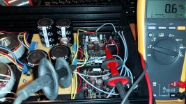
Some figures of the amp (after 30min.) below. As you can see, the ripple is even smaller than predicted:
- V+ 13.25 V DC (0.6 mV AC; see photo)
- V- -13.24 V DC (0.6 mV AC)
- The outputs have 31-35 mV (left) and 36-40 mV DC offset. My Fluke 179 shows 0.4 mV AC at the outputs.
I can recommend this amp to anyone wanting to learn more about noisy power supplies!
Attachments
To be precise, I did not suggest you use 11R.
I merely mentioned what I used for my own design as an example.
"In the DAO, I use 10,000µF-11R-10,000µF. Corner frequency is 1.4Hz.....
.....Feel free to change any of the component values and see how output voltage, transformer current, etc. changes."
Patrick
I merely mentioned what I used for my own design as an example.
"In the DAO, I use 10,000µF-11R-10,000µF. Corner frequency is 1.4Hz.....
.....Feel free to change any of the component values and see how output voltage, transformer current, etc. changes."
Patrick
This thing gets hot!
I used a Hifi2000 Galaxy Maggiorato enclosure Galaxy Maggiorato GX288 230 x 280 mm pannello frontale 10mm NERO (but with a 3 mm instead of 10 mm front panel, total ca. 1.5 kg aluminium) and fixed the 4 output MOSFETs to the 2 mm bottom panel. After 2-3 hours, the bottom plate is about 53 C. The highest temp I can measure on the other panels (side and top) is about 45 C.
Has anyone else built this amp? Just wondering about the heat output because in the 6 moons article Srajan writes:
Not complaining, just wondering.
I hope to have some time later this week to listen to it and will let you know how it sounds.
I used a Hifi2000 Galaxy Maggiorato enclosure Galaxy Maggiorato GX288 230 x 280 mm pannello frontale 10mm NERO (but with a 3 mm instead of 10 mm front panel, total ca. 1.5 kg aluminium) and fixed the 4 output MOSFETs to the 2 mm bottom panel. After 2-3 hours, the bottom plate is about 53 C. The highest temp I can measure on the other panels (side and top) is about 45 C.
Has anyone else built this amp? Just wondering about the heat output because in the 6 moons article Srajan writes:
I also like that the amp can remain on 24/7 and barely gets warm to the touch.
The enclosure in the photo's of the article does not show any heatsinking and I assume "barely gets warm" does not mean > 50 C!
Not complaining, just wondering.
I hope to have some time later this week to listen to it and will let you know how it sounds.
The amp is using quite a bit of power and gets rather hot. I am unsure if this is intentional or due to a mistake in Metalman's schematic (as I mentioned previously there are discrepancies between the description in the 6 moons article + photo's and the published schematic).
Intuitively it feels that 500mA is quite a lot for a rather small IRF610. Compared the standard 200mV mentioned in the F4 thread, which corresponds to 425mA for each much larger IRFP240 or IRFP9240 (albeit that these run at higher rail levels and dissipation depends on V^2), it does seem quite high.
A lower current would also make it much easier on the power supply. Do I really need 500mA going thorough each IRF610?
Althought it is a different design, the F5 headamp EUVL described uses the same IRF610. I assume that if the IRF610 needs 500mA to sound "good" EUVL would bias it to this level. He does not. In the F5 headamp thread, Patrick writes:
With a 50 ohm load, it can output 10V 200mA and still has low distortion (120mA bias min.)
That would be 1W rms.
If you want to use a 30 ohm load, then I suggest increasing bias to 150~180mA.
If you have a 300 ohm load, you can increase voltage to not more than 20V.
But the hungry phones for which this is designed are all 50 ohm or below anyhow.
Based on the above I assume that I do not really need 500mA going through each IRF610.
I use a 250R headphone (Beyerdynamic DT-770 Pro), rated at 100mW max. Using P = V^2/R, max. V is 5V and corresponding I is 20mA.
The 300R Sennheiser HD800 headphone is rated at 500mW max. Using P = V^2/R, max. V is 12.2V and corresponding I is 41mA.
Whatever the actual numbers are going to be, I think it is save to say that 200mA bias should be more than enough. Can I change the schematic to achieve this? If so, how would it sound?
I can of course change the values of parts and measure the results, but this seemed a good time to learn more about LTspice.
Using LTspice I have figured out that I can lower the bias to about 200mA by lowering R19 from 50K to 16K. I then wanted to look at the AC gain (said to sound best at about 50%) but at these bias levels, I wonder if the AC gain is going to make much of a difference.
While playing around with LTspice I ran into trouble. My input is a nice sine wave but my output does not look so nice. What am I doing wrong? Can someone point me in the right direction?
Thanks,
Albert
PS I copied the IRF610 and IRF9610 models from the F5 headamp spice file. The ZTX450 model came from the net, as did the 1N757 I used for the 9.1V zener (I could not find the model for the zener I used but assumed it would be OK).
Attachments
Hi EUVL and ZenMod,
Thanks for your comments.
I had a quick look at the spice files and see EUVL changed the schematic slightly, and that there is a nice sine wave at the output!
I need more time playing with LTspice to see what kind of information I can extract. One thing is certain, the Aleph H is indeed turning out to be a very nice test amp. Due to its size it is easier to work with than any of the bigger/heavier Aleph's (wheelchair user ) and with headphones you notice hum and noise that you would not hear with speakers.
It will take me some time to see what the effects of the changes are and to try to understand why EUVL made these. I can also simulate the changes ZenMod suggested and see what the effects are.
Thanks, and I will keep you updated on my progress.
Albert
Thanks for your comments.
I had a quick look at the spice files and see EUVL changed the schematic slightly, and that there is a nice sine wave at the output!
I need more time playing with LTspice to see what kind of information I can extract. One thing is certain, the Aleph H is indeed turning out to be a very nice test amp. Due to its size it is easier to work with than any of the bigger/heavier Aleph's (wheelchair user
) and with headphones you notice hum and noise that you would not hear with speakers.It will take me some time to see what the effects of the changes are and to try to understand why EUVL made these. I can also simulate the changes ZenMod suggested and see what the effects are.
Thanks, and I will keep you updated on my progress.
Albert
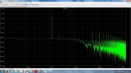
LTspice is a great tool! I have been playing with a number of parameters and have enclosed my latest schematic. Bias is decreased (to about 270mA) by reducing the source resistors to 2R2. Interestingly, THD is very low when R22 and R23 are 2R2. See FFT plot.
Decreasing R22 and R23 to 1 or 0R47 raises THD (and introduces some 2nd harmonics). FFT plot for 0R47 attached.
The same happens when you increase the value of R22 and R23. FFT plot for 4R7 attached.
I have no idea what this amp would sound like, and being new to this have no reference to which I can compare the graphs and numbers I get with. I assume that with experience this should become more intuitive and easy to interpret
Perhaps for now I should rebuild the amp in such a way that it is easy to swap resistors to see what the differences are?
I have plenty of cheap chinese 1/4W metalfilm resistors that I could play around with. When I look at the dissipation that LTspice predicts across R22 and R23, I assume I can use 1/4W resistors?
The LTspice simulation calculates a dissipation of about 135mW across R35 (129mW across R29). Is it OK to use 1/4W resistors here as well?
Thanks,
Albert
Attachments


After some (repeated minor and major) surgery, my Aleph H is up and running and sounds great. Schematic attached.
Reducing the bias has meant that I have higher rail voltage (just over 15V) with one 2x12V 30VA toroid than previously with two (just over 13V). No ripple to speak of (0.5 mV) due to overkill 68k/2R2/68k CRC psu.
The current rail voltage is a bit close to the maximum voltage rating of the psu caps (16V) and the first bank caps will see higher values. I will change the PSU in due course and it will be interesting to see if the sound changes with a psu based on 7812/7912 regulators. Also a good time to learn about cap multiplier circuits.
A few things to note when comparing my version to Metalman's:
1. No XLR input required, so removed R3, C5 + R5 and Z3 + Z4 (LTspice showed reduced noise).
2. Added 47nF ceramic across Z5 (had read it could be beneficial)
3. Added 3pF across R7 (EUVL suggested 3.3pF but I only had 3pF ceramic).
4. Reduced bias by increasing R29 and R35 from 1R to 3R15. Simulation showed about 100mW dissipation, hence used parallel 6R3 1/4W. Also increased R22 and R23 from 0R47 to 1R5 1/4W (simulation showed very small dissipation so no need to parallel; schematic has error in label: R23b instead of R22).
5. Removed Q4, R15 and R16 protection circuit as suggested by EUVL and by Nelson in Aleph Reloaded thread (LTspice showed reduced noise). Did not increase R32 as suggested by EUVL: LTspice showed no difference that I could see. @EUVL: Why did you increase R32? Should I increase it?
6. Tried the amp without R1 (1K) on input but this did not go well with my sources. A lot of distortion with one source, hardly any sound with another.
One mp3 player source still has noise when not playing (no noise as soon as you hit play). This does not happen using an old opamp based headamp. I will try higher values later to see if that solves the problem.
7. I did not use 1N757 for 9.1V Zeners as in schematic, but it was the only spice model I could find.
8. The two 1megaR Rmeasurepoint+/- resistors in schematic were included in order to calculate psu requirements in LTspice. These were not included in build.
9. Had read that a high R resistor could reduce DC offset. Simulation in LTspice suggested 3.9 megaR would reduce DC offset to zero. Tried it but this resulted in high negative DC offset so removed it again. Shows that simulation is not real world
DC offset in small, so no problem.
Next step is to get some hours on the amp and do some serious listening!
Thanks to everyone for your help.
Albert
PS Forgot to mention that the amp is much cooler. After 30min 35 C on transistors. A cool amp is much better for summer
Attachments
Last edited:
If you have too much voltage, you can add 2R power resistors between rectifiers and first C's.
47n is way too little for 9V zener. I would use at least 220µ Elna // 0.1µ MKP.
3.3p wants to be mica or polystyrol. Ceramic is the worst you can choose (they are piezoelectric).
R32 at 470R gives you a smoother frequency response drop. You need to look at frequency response to 10MHz.
Patrick
47n is way too little for 9V zener. I would use at least 220µ Elna // 0.1µ MKP.
3.3p wants to be mica or polystyrol. Ceramic is the worst you can choose (they are piezoelectric).
R32 at 470R gives you a smoother frequency response drop. You need to look at frequency response to 10MHz.
Patrick
Thanks Patrick.
The 2R resistors are a good tip and something I should have thought of (you included resistors before the first C in the psu spice file you uploaded).
Before I order any caps (besides a set of ceramics, I only have Elna Silmic II's in 2 or 3 values and some 4.7uF axial MKP) it is probably a good time to start reading more about how zener diodes work so I understand why a cap is required and how to calculate a sensible value (range).
After a quick change of R32 from 221R to 470R in LTspice, I did not notice any obvious difference on the FFT graph. Will check that out in more detail now I know what I am looking for.
It will be interesting to see how actual measurements of the amp compare to the simulations. Having read positive reviews (for this price range), I bought a Rigol DS1054Z (which I understand has FFT analysis built-in). Cannot do anything with it yet as I first need to figure out how the thing works (never used a scope before) and need to decide which function generator to buy. The Owon AG1012 is relatively cheap but I have no idea if it would be suitable.
Albert
- Home
- Amplifiers
- Pass Labs
- Aleph H Schematic - Revealed at Last