It's not exactly nonsense, if one tunes the crossover to have a high and peaky Q it will add in a hump to the response at the expense of a lower input impedance.
I think we can probably assume that the crossover for mid to tweeter in the GS20 is going to be similar to the GS10s response, where we can see that this isn't a problem.
Well, I think perhaps I mis-poke a little, it was more for the idea that an incorrect component will make a driver louder than "if it had no crossover at all" where I can't see any possible way that adding anything to a crossover somehow makes a driver louder than if it was naked.
Well, if the owner of the speakers only tested my solution...
5th element, you too are wrong.
I never said the driver Q, I was referring to the filter Q. A filter with a Q of 0.707 or a Butterworth type filter is 'maximally flat' and shows absolutely no peaking. Once you go beyond this point, with a higher Q you end up creating a small hump in the response that deviates above the nominally flat portion of the pass band. THe further up you go with the filter Q the larger the deviation becomes and at high Qs you end up with large peaking.
Most likely what is going on with these speakers. 6 uF with such a small inductor? Disaster.
We can see that that isn't what's going on with these loudspeakers. The Stereophile review shows that in the GS10s, the two way version of these two and a half way speakers, that there is no peaking around the xover frequency like this whatsoever. It is unlikely to be causing the issue with these speakers too, although granted, it's not 100% certain.
The inductor isn't that small either. The series pass inductor of the upper mid/bass is most likely the smaller of the two cored inductors, so is likely to be at least 1mH in value.
It depends on the drivers Le and Re about how much of a disaster that actually would become. With a low Le driver, which this could quite easily be, it's not really a problem. We can see that it isn't a problem though because the GS10 is clearly designed by a competent person.
I think the inductor is about 1mH.
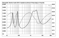
Here is a measurement of the GS20 done by stereophile. It is the top trace.
It looks almost identical to the GS10 throughout the xover frequency and we can see from the GS10s measurements that the xover shows no peaking whatsoever throughout the transition band of the mid/bass.
I think the inductor is about 1mH.
Here is a measurement of the GS20 done by stereophile. It is the top trace.
An externally hosted image should be here but it was not working when we last tested it.
It looks almost identical to the GS10 throughout the xover frequency and we can see from the GS10s measurements that the xover shows no peaking whatsoever throughout the transition band of the mid/bass.
DrDyna, you are wrong. Accept it. Study up on the subject.
Help me understand how having a filter component present versus having no crossover at all somehow makes a driver louder please, because I'm sure there are several laws of physics that would beg to differ.
If adding components makes drivers louder, than why don't we all just empty our parts bins into our crossovers and enjoy free power?
DrDyna, I'll tell you when I please. Meanwhile, be aware of that I have the fundamentals of crossover design in the clear, and you do not. And neither does you friend in nastiness, sreten. Perhaps you two can help each other out to an understanding? You two are so above the rest of us.
Help me understand how having a filter component present versus having no crossover at all somehow makes a driver louder please, because I'm sure there are several laws of physics that would beg to differ.
If adding components makes drivers louder, than why don't we all just empty our parts bins into our crossovers and enjoy free power?
It's to do with impedance being interrelated to frequency response. For a High Q filter setup like a chebysheff, you peak output at a low impedance. By contrast, Linkwitz_riley has a rise in impedance corresponding to a less peaky output at a lower Q. The power calculation is modified by the load impedance so you're not breaking the laws of energy conservation. Butterworth falls between the two, being overall flat impedance with a slight SPL rise due to having two drivers reinforcing each other.
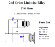
In this case we seem to be looking at Linkwitz-Riley filters by the impedance signature at 2700Hz, which is the crossover frequency I reckon. As strawberry has picked up, the filter rolloffs seem slightly staggered, hence the untidy double hump at crossover.
Attachments
Last edited:
No!
The SEAS tweeter you've already got is most likely, more then capable.
If you want to spend some money on this then my advice to you is to buy a microphone and mic preamp, then use some freeware, such as ARTA to take measurements of the loudspeakers. This doesn't have to be too expensive, the Behringer ECM8000 should be fine as a mic, as should any cheap mic pre with phantom power and without a rumble filter, be fine too. I know you're experienced in electronics design so you could perhaps even build your own mic pre
If you can take meaningful measurements of the drive units, without a crossover, in your loudspeakers, then there will be plenty of people here (myself included) who would be more then happy to assist you in designing a new crossover. I have written a short guide on making useful loudspeaker measurements when using ARTA too if you're interested.
I wanna take your advice and do some measuring on drivers.
This is what I found as a combo at a very good price (80eur):
Preamplificator microfon Behringer MIC100 (147,26RON) Partysound
Microfon Omnidirectional de masura Behringer ECM8000 (202,78RON) Partysound
Can I get your short guide on making useful loudspeaker measurements when using ARTA, please?
Thanks,
Mihai
Frd/Zma's of the drivers would not be bad, for simulation.I wanna take your advice and do some measuring on drivers.
This is what I found as a combo at a very good price (80eur):
Preamplificator microfon Behringer MIC100 (147,26RON) Partysound
Microfon Omnidirectional de masura Behringer ECM8000 (202,78RON) Partysound
Can I get your short guide on making useful loudspeaker measurements when using ARTA, please?
Thanks,
Mihai
Measuring inductors, another nice idea, for simulation.
This is an approxim. simulation of the crossover electrical response.
Attachments
Last edited:
It's to do with impedance being interrelated to frequency response. For a High Q filter setup like a chebysheff, you peak output at a low impedance. By contrast, Linkwitz_riley has a rise in impedance corresponding to a less peaky output at a lower Q. The power calculation is modified by the load impedance so you're not breaking the laws of energy conservation. Butterworth falls between the two, being overall flat impedance with a slight SPL rise due to having two drivers reinforcing each other.
In this case we seem to be looking at Linkwitz-Riley filters by the impedance signature at 2700Hz, which is the crossover frequency I reckon. As strawberry has picked up, the filter rolloffs seem slightly staggered, hence the untidy double hump at crossover.
Right, but in any of the crossover alignments, would removing the filter entirely make any one driver louder? I understand what you're saying, but that's not what he said.
if you put a too big capacitor in it makes the high end of the driver, near the crossover frequency, play far too loud, louder than if no crossover had been present at all.
What's more is, while we might be able to deduce from the impedance profile that the MA filter circuit might be a little off, should we try and figure out what should be changed using a simulation and suggest alternate values to address it? Maybe even post that simulation? or should we just say "meh, flip the capacitors around and add this arbitrary value that I can't explain how I came up with." and then when people invariably say "What are you talking about?" have a two paragraph tantrum that still doesn't address anything relevant unless you consider butthurt raving about our psychological health to be germane to the discussion.
Frd/Zma's of the drivers would not be bad, for simulation.
Measuring inductors, another nice idea, for simulation.
This is an approxim. simulation of the crossover electrical response.
This is an example of helpful information, now I've got my listening ears on, hopefully we can see where this goes without anymore conjecture and tourette's.
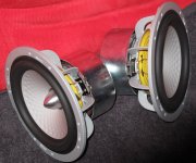
I don't know if it helps but the midrange driver has 5.5 ohms DC resistance and 1867grams weight ") Bass driver has 11.2 ohms DC resistance and 1788 grams weight
Bass driver has 11.2 ohms DC resistance and 1788 grams weight
When I'll get from a friend of mine a properly calibrated L-meter I will measure all the inductances including drivers voice coils.
Bass driver has 11.2 ohms DC resistance and 1788 grams weightWhen I'll get from a friend of mine a properly calibrated L-meter I will measure all the inductances including drivers voice coils.
Attachments
I would hope tempers have cooled now, and we've all got our thinking caps focussed on a solution, if one exists...
Here's what we know at the moment aside from the fact that these are tricky metal drivers with all sorts of unpleasant resonances:
Tanks (aka Traps) and notches (of which MA have fitted one on the midbass) have an unpleasant effect on impedance. IMO, it's gonna be more doable to modify the crossover to third order and attenuate the ringing beyond crossover point. The impedance plot also showed a resonance at 27 kHz and an unfortunate rise in impedance beyond, which will affect some amplifiers more than others, which is why an L-pad on the tweeter might help. The bass unit could perhaps go to second order.
As Troels has often noted, metal cones always sound like metal cones, and polys like polys, so I'm not expecting miracles here however good the fix!
Here's what we know at the moment aside from the fact that these are tricky metal drivers with all sorts of unpleasant resonances:
An externally hosted image should be here but it was not working when we last tested it.
Tanks (aka Traps) and notches (of which MA have fitted one on the midbass) have an unpleasant effect on impedance. IMO, it's gonna be more doable to modify the crossover to third order and attenuate the ringing beyond crossover point. The impedance plot also showed a resonance at 27 kHz and an unfortunate rise in impedance beyond, which will affect some amplifiers more than others, which is why an L-pad on the tweeter might help. The bass unit could perhaps go to second order.
As Troels has often noted, metal cones always sound like metal cones, and polys like polys, so I'm not expecting miracles here however good the fix!
Also as you said on post #16, soft domes are a much better standard choice for common loudspeakers (than 40kHz buzzing tweeters)....which is why an L-pad on the tweeter might help. The bass unit could perhaps go to second order.
As Troels has often noted, metal cones always sound like metal cones, and polys like polys, so I'm not expecting miracles here however good the fix!
I wonder if an easy check/test with a resistor between the bi-wire bi-amp connector posts is an easy go, for the high frequencies only attenuation.
Guys,
A look at the tweeter+filter response in post nr 31 is quite revealing.
It can been seen that at approx. 7 kHz the tweeter plot steeply rises tot +7 db at 12kHz.
This very sudden, not gradual, rise in response might well be the reason for the somewhat bright sound of this system, in my experience at least.
My suggestion would be to, instead of changing drivers or upgrading to boutique components, redesign the high pass section with an LCR trap. This will not be trivial, since a suck-out LCR trap at approx 11 kHz will be needed to flatten out the tweeter on axis.
Measure and import your .FRD and .ZMA files into BoxSim.
Be prepared with BoxSim, however, you will have quite a job to simulate such a suck-out plus hi-pass.
After such an optimization, a little experimenting with tweeter levels through a series plus parallel resistor can work miracles in the overall presentation of a multi-way loudspeaker.
Furthermore, it seems to me the LCR trap in the low-pass section is also sub-optimal.
Have fun and experiment before you start buying new drivers.
Eelco
Hi,
Measuring the drivers is a good idea, but it is not a trivial task to
do accurately, and something of a minefield for the inexperienced.
rgds, sreten.
Trying to fix alleged apparent "problems" in the impedance curve,
(of a speaker that may or may not be similar), is the cart before
the horse, you can't derive the acoustic response or acoustic
filter functions of a loudspeaker from the impedance curve.
(Except in the bass for simple boxes.)
It doesn't look like 0.5 mH and 6 uF will be the disaster I spoke of. The capacitor is still too small to create the hump in output that is possible otherwise. From the second order crossover it looks like the mid driver is following its raw output up to about 3 kHz, and then it rolls off. But the trap around 7 kHz should cut out the unwanted peaks. A swap of the 4 uF and 6 uF is still a good idea and should be tested. 20 uF on the woofer. And it's just a test, and a fair guess, so no, the world will not go under, and there is no need to get nasty.
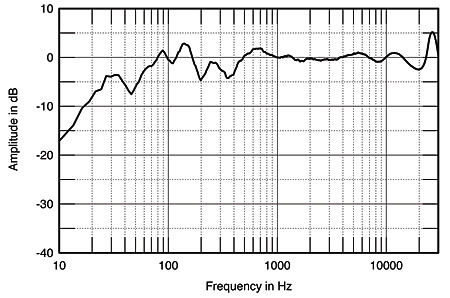
Fig.7 Monitor Audio GS10, spatially averaged, 1/6-octave response in JA's listening room.
Hi,
Given the debate regarding the GS10 x/o you can't really argue
with the above. There is no sign of any real issues at the x/o point.
It does look somewhat hot at the top in general, a more HT like
flat power response in the treble than the more old school hifi
flat on axis response with an inevitably drooping top end power
response.
Personally I think this thread has wandered way off what can
be sensibly and simply done to adjust the voicing of the
speaker without messing up MA's basic engineering.
rgds, sreten.
Clearly both you and the original designer shares the same poor taste or ignorance.
Hi,
Clearly most commercial loudspeaker companies employ people to
design their speakers who are mindless muppets like me who don't
have clue what that they are doing and keep screwing it up. If only
they had someone like you, who shown a x/o schematic can tell
whats wrong with it and how it can be improved.
Sprinkle your magic on this :

Its a TMM allegedly 2nd order L/R at 3KHz.
Assume for some reason not adequately nailed down,
the owner thinks the crossover can be improved.
rgds, sreten.
Last edited:
- Status
- This old topic is closed. If you want to reopen this topic, contact a moderator using the "Report Post" button.
- Home
- Loudspeakers
- Multi-Way
- Please help for Monitor Audio GS20 crossover tuning