A couple of extra quirks I have noticed during usage:
Sometimes (maybe 5% of the time) the upload to the board goes a little 'wrong'. This can be seen by strange oscillations in measured response and generally a far lower gain (-20dB?) on the outputs. Disconnecting and reuploading identical settings seems to fix.
The bluetooth volume control seems to only increase gain in the first 20% of my phones volume, after that it has no effect. It is fully updated Android and works fine with everything else.
When connecting my laptop to the unit via 3.5mm and USB for programming, it seems to always set the battery LED to red. Really doesn't matter, but didn't expect that behaviour.
Otherwise, it's rocking!")
Sometimes (maybe 5% of the time) the upload to the board goes a little 'wrong'. This can be seen by strange oscillations in measured response and generally a far lower gain (-20dB?) on the outputs. Disconnecting and reuploading identical settings seems to fix.
The bluetooth volume control seems to only increase gain in the first 20% of my phones volume, after that it has no effect. It is fully updated Android and works fine with everything else.
When connecting my laptop to the unit via 3.5mm and USB for programming, it seems to always set the battery LED to red. Really doesn't matter, but didn't expect that behaviour.
Otherwise, it's rocking!
There's something wrong with the latest version programmer and my amp -
I of course wanted to try the new V1.1.3 with its nice graphs. I set it up with the EQ and crossover points as needed, left and right input, dual outputs - pretty much a copy of the V1.1.2 setup. Audio balance is definitely skewed to the left channel, but plays in stereo.
Back to programming with V1.1.2 and it again plays normally. Back to V1.1.3 (am I crazy / hearing things?) and it again definitely plays left channel louder. Back to V1.1.2 and it plays normally - perfectly balanced.
How can that possibly be? I use V1.1.3 to look at the graphs, V1.1.2 to setup the amp -
I notice the "firmware update" button is missing from the V1.1.3 panel; is my (Feb 2020) amp in need of a firmware update to work properly with V1.1.3? I'm at 1.1.1
Here's the V1.1.3 log.
UPLOAD STARTED
OUTPUT: ECHO
INPUT: ECHO
OUTPUT: MODEL
INPUT: AIO4CH
OUTPUT: FIRMWARE
INPUT: 1.1.1
OUTPUT: EEPROM BEGIN
OUTPUT: VOLSTART -30
OUTPUT: VOLMAX 0
OUTPUT: POWERLOW 0
OUTPUT: POWERSHUTDOWN 0
OUTPUT: I2C AMP1 0X8C 0X0B 0X14 0X0 0X80 0X0 0X0 0X0 0X80 0X0 0X0
OUTPUT: I2C AMP2 0X8C 0X0B 0X14 0X0 0X0 0X0 0X0 0X0 0X80 0X0 0X0
OUTPUT: I2C DUAL 0XAA 0X01 0X30 0X8 0X0 0X0 0X0 0X0 0X0 0X0 0X0 0X0 0X0 0X0 0X0 0X0 0X0 0X0 0X0 0X0 0X0 0X0 0X0
OUTPUT: I2C DUAL 0XAA 0X01 0X44 0X8 0X0 0X0 0X0 0X0 0X0 0X0 0X0 0X0 0X0 0X0 0X0 0X0 0X0 0X0 0X0 0X0 0X0 0X0 0X0
OUTPUT: I2C DUAL 0XAA 0X01 0X58 0X8 0X0 0X0 0X0 0X0 0X0 0X0 0X0 0X0 0X0 0X0 0X0 0X0 0X0 0X0 0X0 0X0 0X0 0X0 0X0
OUTPUT: I2C DUAL 0XAA 0X01 0X6C 0X8 0X0 0X0 0X0 0X0 0X0 0X0 0X0 0X0 0X0 0X0 0X0 0X0 0X0 0X0 0X0 0X0 0X0 0X0 0X0
OUTPUT: I2C DUAL 0XAA 0X02 0X08 0X8 0X0 0X0 0X0 0X0 0X0 0X0 0X0 0X0 0X0 0X0 0X0 0X0 0X0 0X0 0X0 0X0 0X0 0X0 0X0
OUTPUT: I2C DUAL 0XAA 0X02 0X1C 0X8 0X0 0X0 0X0 0X0 0X0 0X0 0X0 0X0 0X0 0X0 0X0 0X0 0X0 0X0 0X0 0X0 0X0 0X0 0X0
OUTPUT: I2C DUAL 0XAA 0X02 0X30 0X8 0X0 0X0 0X0 0X0 0X0 0X0 0X0 0X0 0X0 0X0 0X0 0X0 0X0 0X0 0X0 0X0 0X0 0X0 0X0
OUTPUT: I2C DUAL 0XAA 0X02 0X44 0X8 0X0 0X0 0X0 0X0 0X0 0X0 0X0 0X0 0X0 0X0 0X0 0X0 0X0 0X0 0X0 0X0 0X0 0X0 0X0
OUTPUT: I2C DUAL 0XAA 0X02 0X58 0X8 0X0 0X0 0X0 0X0 0X0 0X0 0X0 0X0 0X0 0X0 0X0 0X0 0X0 0X0 0X0 0X0 0X0 0X0 0X0
OUTPUT: I2C DUAL 0XAA 0X02 0X6C 0X8 0X0 0X0 0X0 0X0 0X0 0X0 0X0 0X0 0X0 0X0 0X0 0X0 0X0 0X0 0X0 0X0 0X0 0X0 0X0
OUTPUT: I2C DUAL 0XAA 0X03 0X08 0X8 0X0 0X0 0X0 0X0 0X0 0X0 0X0 0X0 0X0 0X0 0X0 0X0 0X0 0X0 0X0 0X0 0X0 0X0 0X0
OUTPUT: I2C DUAL 0XAA 0X03 0X1C 0X8 0X0 0X0 0X0 0X0 0X0 0X0 0X0 0X0 0X0 0X0 0X0 0X0 0X0 0X0 0X0 0X0 0X0 0X0 0X0
OUTPUT: I2C DUAL 0XAA 0X03 0X30 0X8 0X0 0X0 0X0 0X0 0X0 0X0 0X0 0X0 0X0 0X0 0X0 0X0 0X0 0X0 0X0 0X0 0X0 0X0 0X0
OUTPUT: I2C_EQ DUAL 0XAA 0X03 0X44 0X8 0X0 0X0 0X0 0X0 0X0 0X0 0X0 0X0 0X0 0X0 0X0 0X0 0X0 0X0 0X0 0X0 0X0 0X0 0X0
OUTPUT: I2C_EQ DUAL 0XAA 0X03 0X58 0X8 0X0 0X0 0X0 0X0 0X0 0X0 0X0 0X0 0X0 0X0 0X0 0X0 0X0 0X0 0X0 0X0 0X0 0X0 0X0
OUTPUT: I2C DUAL 0XAA 0X15 0X34 0X8 0X0 0X0 0X0 0X0 0X0 0X0 0X0 0X0 0X0 0X0 0X0 0X0 0X0 0X0 0X0 0X0 0X0 0X0 0X0
OUTPUT: I2C DUAL 0XAA 0X15 0X48 0X8 0X0 0X0 0X0 0X0 0X0 0X0 0X0 0X0 0X0 0X0 0X0 0X0 0X0 0X0 0X0 0X0 0X0 0X0 0X0
OUTPUT: I2C DUAL 0XAA 0X15 0X5C 0X8 0X0 0X0 0X0 0X0 0X0 0X0 0X0 0X0 0X0 0X0 0X0 0X0 0X0 0X0 0X0 0X0 0X0 0X0 0X0
OUTPUT: I2C DUAL 0XAA 0X15 0X70 0X8 0X0 0X0 0X0 0X0 0X0 0X0 0X0 0X0 0X0 0X0 0X0 0X0 0X0 0X0 0X0
OUTPUT: I2C DUAL 0XAA 0X16 0X08 0X0 0X0 0X0 0X0
OUTPUT: I2C AMP1 0XAA 0X0F 0X10 0X8 0X0 0X0 0X0 0X0 0X0 0X0 0X0 0X0 0X0 0X0 0X0 0X0 0X0 0X0 0X0 0X0 0X0 0X0 0X0
OUTPUT: I2C AMP1 0XAA 0X0F 0X24 0X8 0X0 0X0 0X0 0X0 0X0 0X0 0X0 0X0 0X0 0X0 0X0 0X0 0X0 0X0 0X0 0X0 0X0 0X0 0X0
OUTPUT: I2C AMP1 0XAA 0X0F 0X38 0X8 0X0 0X0 0X0 0X0 0X0 0X0 0X0 0X0 0X0 0X0 0X0 0X0 0X0 0X0 0X0 0X0 0X0 0X0 0X0
OUTPUT: I2C AMP1 0XAA 0X0F 0X4C 0X8 0X0 0X0 0X0 0X0 0X0 0X0 0X0 0X0 0X0 0X0 0X0 0X0 0X0 0X0 0X0 0X0 0X0 0X0 0X0
OUTPUT: I2C AMP1 0XAA 0X0F 0X60 0X8 0X0 0X0 0X0 0X0 0X0 0X0 0X0 0X0 0X0 0X0 0X0 0X0 0X0 0X0 0X0 0X0 0X0 0X0 0X0
OUTPUT: I2C AMP1 0XAA 0X0F 0X74 0X8 0X0 0X0 0X0 0X0 0X0 0X0 0X0 0X0 0X0 0X0 0X0
OUTPUT: I2C AMP1 0XAA 0X10 0X08 0X0 0X0 0X0 0X0 0X0 0X0 0X0 0X0
OUTPUT: I2C AMP1 0XAA 0X10 0X10 0X8 0X0 0X0 0X0 0X0 0X0 0X0 0X0 0X0 0X0 0X0 0X0 0X0 0X0 0X0 0X0 0X0 0X0 0X0 0X0
OUTPUT: I2C AMP1 0XAA 0X10 0X24 0X8 0X0 0X0 0X0 0X0 0X0 0X0 0X0 0X0 0X0 0X0 0X0 0X0 0X0 0X0 0X0 0X0 0X0 0X0 0X0
OUTPUT: I2C AMP1 0XAA 0X10 0X38 0X8 0X0 0X0 0X0 0X0 0X0 0X0 0X0 0X0 0X0 0X0 0X0 0X0 0X0 0X0 0X0 0X0 0X0 0X0 0X0
OUTPUT: I2C AMP1 0XAA 0X10 0X4C 0X8 0X0 0X0 0X0 0X0 0X0 0X0 0X0 0X0 0X0 0X0 0X0 0X0 0X0 0X0 0X0 0X0 0X0 0X0 0X0
OUTPUT: I2C AMP2 0XAA 0X0F 0X10 0X8 0X0 0X0 0X0 0X0 0X0 0X0 0X0 0X0 0X0 0X0 0X0 0X0 0X0 0X0 0X0 0X0 0X0 0X0 0X0
OUTPUT: I2C AMP2 0XAA 0X0F 0X24 0X8 0X0 0X0 0X0 0X0 0X0 0X0 0X0 0X0 0X0 0X0 0X0 0X0 0X0 0X0 0X0 0X0 0X0 0X0 0X0
OUTPUT: I2C AMP2 0XAA 0X0F 0X38 0X8 0X0 0X0 0X0 0X0 0X0 0X0 0X0 0X0 0X0 0X0 0X0 0X0 0X0 0X0 0X0 0X0 0X0 0X0 0X0
OUTPUT: I2C AMP2 0XAA 0X0F 0X4C 0X8 0X0 0X0 0X0 0X0 0X0 0X0 0X0 0X0 0X0 0X0 0X0 0X0 0X0 0X0 0X0 0X0 0X0 0X0 0X0
OUTPUT: I2C AMP2 0XAA 0X0F 0X60 0X8 0X0 0X0 0X0 0X0 0X0 0X0 0X0 0X0 0X0 0X0 0X0 0X0 0X0 0X0 0X0 0X0 0X0 0X0 0X0
OUTPUT: I2C AMP2 0XAA 0X0F 0X74 0X8 0X0 0X0 0X0 0X0 0X0 0X0 0X0 0X0 0X0 0X0 0X0
OUTPUT: I2C AMP2 0XAA 0X10 0X08 0X0 0X0 0X0 0X0 0X0 0X0 0X0 0X0
OUTPUT: I2C AMP2 0XAA 0X10 0X10 0X8 0X0 0X0 0X0 0X0 0X0 0X0 0X0 0X0 0X0 0X0 0X0 0X0 0X0 0X0 0X0 0X0 0X0 0X0 0X0
OUTPUT: I2C AMP2 0XAA 0X10 0X24 0X8 0X0 0X0 0X0 0X0 0X0 0X0 0X0 0X0 0X0 0X0 0X0 0X0 0X0 0X0 0X0 0X0 0X0 0X0 0X0
OUTPUT: I2C AMP2 0XAA 0X10 0X38 0X8 0X0 0X0 0X0 0X0 0X0 0X0 0X0 0X0 0X0 0X0 0X0 0X0 0X0 0X0 0X0 0X0 0X0 0X0 0X0
OUTPUT: I2C AMP2 0XAA 0X10 0X4C 0X8 0X0 0X0 0X0 0X0 0X0 0X0 0X0 0X0 0X0 0X0 0X0 0X0 0X0 0X0 0X0 0X0 0X0 0X0 0X0
OUTPUT: I2C AMP1 0X8C 0X0E 0X7C 0X0 0X0 0X0 0X0
OUTPUT: I2C AMP1 0X8C 0X0F 0X0C 0X0 0X0 0X0 0X0
OUTPUT: I2C AMP2 0X8C 0X0E 0X7C 0X0 0X0 0X0 0X0
OUTPUT: I2C AMP2 0X8C 0X0F 0X0C 0X0 0X0 0X0 0X0
OUTPUT: I2C AMP1 0X0 0X0 0X02 0X41
OUTPUT: I2C AMP2 0X0 0X0 0X02 0X41
OUTPUT: EEPROM END ZOUDIO AIO CONFIGURATION TOOL V1.1.3
SETTINGS UPLOADED TO AIO4CH (FIRMWARE VERSION: 1.1.1)
DISCONNECTED
I already see the issue. The configuration values when setting to 'left' are not okay. I will push an update as soon as possible. If you send me a DM I can send you a temporary fix if needed.
All other settings are not affected.
The firmware update feature has now been placed in the drop-down menu on the upload button under 'upload new firmware'. However, its backwards compatible. A firmware update is not needed.
All other settings are not affected.
The firmware update feature has now been placed in the drop-down menu on the upload button under 'upload new firmware'. However, its backwards compatible. A firmware update is not needed.
Last edited:
Hi lutkeveld - thanks, take your time. I'm good for the time being; system is working and sounds how I want, hopefully doesnt effect other users yet.
Same issue on my end also. Running two boards in TWS. But not a big issue, just turn the left channel down on the rotary switch.
Latest version is released with the input problem fixed.
@zerokelvin
1) Maybe a problem during writing... I will write a memory check into the tool soon. After setting up a link with the board it just assumes writing goes well.
2) I had that too recently. Flashing the BT firmware again with exactly the same firmware (requires a special programmer) fixed it. Maybe has something to do with improper power cycling... Will look into it.
3) Do you have your low power voltage set (not 0)?
You can request the voltage the board measures by sending "VOLTAGE". If you have no power supply connected it will respond with about 2.5V (backfeed via the buckconverter).
THD +N over frequency looks best at 24V with a 1W output for the usual speaker impedances, according to measurements in the TAS5825 spec sheet. I wonder if this follows for even less power out?
Right next to the Zoudio thread is another fellow selling DAC output transformers. 4:1. Not too far a stretch to imagine with resistor padding, connecting such transformers to the AIO4CH output and provide an isolated balanced signal to another amplifier.
A "waste" of an output? Maybe. Or, who cares if it sounds good and can also do things such as the integrated DSP filtering that's hard to find at this price point otherwise. Plenty of drive available to follow with a power tube stage output, that would swamp the distortion values I see for this amp in the spec sheet - with their own "good" distortion. Single ended or push-pull.
Of course, there's a lot cheaper ways to do that using an RC network, but it's not the first time I've read about the "magic box" attributes of line level transformer coupling.
I bought a PCM2706 USB to I2S board off fleabay for $11. There's other such boards that appear to be at least on the same order of size as the BT module. Perhaps a future spin of the mainboard could accommodate both, for a USB connected amplifier option - simply by building it with this module instead of that one.
Attachments
Last edited:
Great looking board!
I was actually wondering what kind of inductors are being used?
For about 100W @ 2ohm continues (RMS, full-time), they seem very small.
They also look a little bit like powdered iron cores? Although it's very hard to see on the pictures.
The issue with these kind of inductors, is that they have a very soft saturation curve, which results in an overall higher distortion. Especially with amplifiers without post-feedback filtering.
For this amount of claimed power, I normally would expect something like a Coilcraft MSS1278 or equivalent (from other brand)
Also, the way to cool this thing is a little confusing.
Seen from the picture elsewhere in this thread, it seems like you totally rely on the cooling capabilities of the PCB?
Or is it also possible to install a thermal pad on the bottom side and screw it to a aluminum plate?
(which is finally a good cooling solution, compared to all the other amplifiers that are available)
At 100 RMS, you will still dissipate about 10W of heat (90% efficiency).
In practice this will be a little lower with music, although that also highly depends on the type of music.
Last edited:
I believe lutkeveld is in the process of designing a plate for his product, which turns it into a "plate amp" which I'm sure will go a long way regarding thermal dissipation. He'll have to enlighten with the details.
>In practice this will be a little lower with music, although that also highly depends on the type of music.
Yes, some of the material I hear emminating from automobiles these days sounds like a full-on synth bass that just switches back and forth between two notes. 10 minutes of that at 100W into 2 would get this little guy cookin I imagine.
Although I've never tested it myself (I only own one and would like to keep it, as it's my sole source these days) from what I read about the TAS chip, it's pretty well thermally protected. So failure should be the music simply cuts-off, versus the amp being destroyed.
The chip is even capable of automatically reducing output as it senses temperature rise into the danger zone, although I'm not certain that feature is captured in the "process flow" being used. The amplifier spec is easily downloadable from TI and it speaks to stuff like how the thermal and cone excusion protection works - and covers output inductor selection criteria.
Last edited:
@Larxxor
Its the built-in ADC from the CSRA64215 bt chip, its 12 bits.
@joe
The CSR has a USB DAC built in, but I have not tried it out yet. Who knows in a future version...
The plate amp option is indeed being worked on, but has no effect on cooling. Its only meant for easy mounting. Adding cooling is possible by attaching a heatsink to the back of the PCB using thermal pads. Have not tried any options myself yet.
@b_force
The chip is thermally limited. It has a similar output stage as the TPA311x, but not the same dissipation options. With music the output is similar to the TPA311x series, but if you play sine waves the output will automatically decrease and return to its original when its possible again.
The inductors are Murata 1274AS-H-100M=P3, the type TI recommends and that are used on the EVM.
@Larxxor
Its the built-in ADC from the CSRA64215 bt chip, its 12 bits.
@joe
The CSR has a USB DAC built in, but I have not tried it out yet. Who knows in a future version...
The plate amp option is indeed being worked on, but has no effect on cooling. Its only meant for easy mounting. Adding cooling is possible by attaching a heatsink to the back of the PCB using thermal pads. Have not tried any options myself yet.
@b_force
The chip is thermally limited. It has a similar output stage as the TPA311x, but not the same dissipation options. With music the output is similar to the TPA311x series, but if you play sine waves the output will automatically decrease and return to its original when its possible again.
I assume that the CSRA64215 Bluetooth firmware can easily be changed by some kind of usb programmer?
The inductors are Murata 1274AS-H-100M=P3, the type TI recommends and that are used on the EVM.
Thanks for clarification.
So, yeah when the amplifier is cooled on a better way, it will also perform much better eventually.
Looking at the Murrata datasheet, and I also think that there is definitely room for improvement for the same footprint.
I assume that the CSRA64215 firmware can easily be changed by some kind of USB programmer?
Last edited:
Thanks for clarification.
So, yeah when the amplifier is cooled on a better way, it will also perform much better eventually.
Looking at the Murrata datasheet, and I also think that there is definitely room for improvement for the same footprint.
@lutkeveld
I assume that the CSRA64215 firmware can easily be changed by some kind of USB programmer?
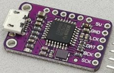
Thanks for building this board which is definitely unique. I have not tried to confirm but the csr chip on the board has an 8 pin plug next to it. Is this available for programming? I have some experience with CSRA64215 and would like to change some settings.

This is a soft warning. It can be pushed quite a bit harder before it starts limiting.
Register 0x73 of the chip contains the temperature:
1 (0b0001) = 112*C
3 (0b0011) = 122*C
7 (0b0111) = 134 *C
15 (0b1111) = 146 *C
If it reads 7 or 15 it decrease the volume temporarily with 1dB/sec. If the output is being reduced, it will tell you how much dB its currently reduced by.
Once the temperature register is 0/1/3 again, it will try to recover to the original volume. This is to prevent that if you push your speaker very hard, you have to walk over to your speaker every once in a while to turn it up again
Same problem with iPhone, iPad and MacBook. Only fixed volume from BT, still adjustable by rotational switch. Our LG television how ever works fine with BT volume.
With 2 modules in TWS volume over BT works with iPhone, iPad etc.
I have informed Jesse in separate mail about the issue.
With 2 modules in TWS volume over BT works with iPhone, iPad etc.
I have informed Jesse in separate mail about the issue.
Last edited:
Its related to a certain setting in the BT firmware. It was set to 'external' instead of digital, which seems not to scale correctly on most devices.
You can update it using a CSR USB SPI programmer or sending it back. You can contact me on info@zoudio.com if you need help.
You can update it using a CSR USB SPI programmer or sending it back. You can contact me on info@zoudio.com if you need help.
LXMini clone with AIO4CH
Lots of spare time in C-19, so time to show an example of what can be made with the Zoudio AIO4CH board.
I am planning to build a pair of clone LXMINI+2, and startet with purchasing the original SEAS drivers FU10RB and L16RN-SL just for the LXMINI itself. For those unfamiliar with the LXMini you might want to check www.linkwitzlab.com. Kits or even finished speakers can be purchased from www.magiclx521.com
The Zoudio board with 4x50w and dsp is a great match for the LXmini. A higher output would be great, but I am not listening at very high volumes anyway.
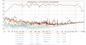
I measured the response using REW and UMIK-1, and adjusted dsp settings from that. Naturally the FU10RB takes a bit of adjustment. I got quite a bit of tips from a LXMini clone builder LXC LXC - cdenneler
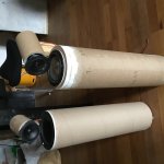
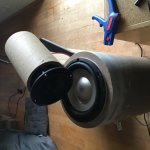
For convenience I used heavy duty cardboard tubes for the cabinets. I will probably wrap them in wool textile for finish. The speaker on the left side is a low cost version using a 6.5” Jamo 21330 woofer that I salvaged from a pair of Jamo 8 classics, glued directly onto the cardboard tube and a VIFA TC9FD18-08. The Jamo is too hard for this small cabinet of 12 l, so not a good match.
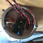
I placed the Zoudio board in the base of the right speaker, and connected the other speaker with a threaded 4 wire cable. Not ideal when it comes to heat, but it works fine so far, and makes for a very compact system. I use a Meanwell 24V 120W external power supply, can probably be a lot smaller.
I am generally listening to levels below 95 dB and it sounds amazing, everything that is written about the LXmini is very true. I tribute the very transparent sound to the Zoudio board.
I had to limit the equalising of the woofer to +8dB, otherwise I got a strange respond where the board would reduce sound levels immediately if low frequency bass was present. I also had to move some of the equalising around to get enough taps. The analog input gives off noise, but only if bluetooth is not connected, once connected the unit is dead silent. Sometimes the BT connection will produce clicks while playing, but a quick disconnect reconnect will fix it. Lutkeveld (Jesse) has been very helpful with support to my questions.
Next step is to build two sub-woofers and switch to two Zoudio boards in TWS. Each board is then running 2.1. I tried already using a set of SEAS 303 speakers as a sub, and it worked great. There is a nice design of an alternative LXMini sub on the LXMini user group ORION/PLUTO/LX... Users Group • View topic - LXmini subwoofer add-on (a.k.a. LXmini+)
"Have fun, create memories!" (Siegfried Linkwitz)
Needless to say, I had a lot of fun making these speakers.
Lots of spare time in C-19, so time to show an example of what can be made with the Zoudio AIO4CH board.
I am planning to build a pair of clone LXMINI+2, and startet with purchasing the original SEAS drivers FU10RB and L16RN-SL just for the LXMINI itself. For those unfamiliar with the LXMini you might want to check www.linkwitzlab.com. Kits or even finished speakers can be purchased from www.magiclx521.com
The Zoudio board with 4x50w and dsp is a great match for the LXmini. A higher output would be great, but I am not listening at very high volumes anyway.
I measured the response using REW and UMIK-1, and adjusted dsp settings from that. Naturally the FU10RB takes a bit of adjustment. I got quite a bit of tips from a LXMini clone builder LXC LXC - cdenneler
For convenience I used heavy duty cardboard tubes for the cabinets. I will probably wrap them in wool textile for finish. The speaker on the left side is a low cost version using a 6.5” Jamo 21330 woofer that I salvaged from a pair of Jamo 8 classics, glued directly onto the cardboard tube and a VIFA TC9FD18-08. The Jamo is too hard for this small cabinet of 12 l, so not a good match.
I placed the Zoudio board in the base of the right speaker, and connected the other speaker with a threaded 4 wire cable. Not ideal when it comes to heat, but it works fine so far, and makes for a very compact system. I use a Meanwell 24V 120W external power supply, can probably be a lot smaller.
I am generally listening to levels below 95 dB and it sounds amazing, everything that is written about the LXmini is very true. I tribute the very transparent sound to the Zoudio board.
I had to limit the equalising of the woofer to +8dB, otherwise I got a strange respond where the board would reduce sound levels immediately if low frequency bass was present. I also had to move some of the equalising around to get enough taps. The analog input gives off noise, but only if bluetooth is not connected, once connected the unit is dead silent. Sometimes the BT connection will produce clicks while playing, but a quick disconnect reconnect will fix it. Lutkeveld (Jesse) has been very helpful with support to my questions.
Next step is to build two sub-woofers and switch to two Zoudio boards in TWS. Each board is then running 2.1. I tried already using a set of SEAS 303 speakers as a sub, and it worked great. There is a nice design of an alternative LXMini sub on the LXMini user group ORION/PLUTO/LX... Users Group • View topic - LXmini subwoofer add-on (a.k.a. LXmini+)
"Have fun, create memories!" (Siegfried Linkwitz)
Needless to say, I had a lot of fun making these speakers.
Attachments
- Home
- Vendor's Bazaar
- ZOUDIO AIO4CH: 4-channel amplifier with DSP and Bluetooth