From TAS5825M "Advanced Features" spec; PVDD Sensing
The PVDD sensing applies smooth compression to maintain consistent dynamic range when the supply voltage (PVDD) varies. This feature is quite useful in the following two scenarios.
1. Customers have the volume turned up too high.
2. PVDD voltage drops due to battery discharging but the input signal still stays same amplitude.
An 8-bit PVDD supply voltage ADC enables the PVDD sensing circuit. Its output provides the necessary inputs to calculate the amount of compression that needs to be applied to signal peaks. In addition, the PVDD ADC results can be read back via I2C through the PVDD_ADC Register located at 0x5E.
The PVDD sensing has two functional modes, depending on the measured value of supply voltage (PVDD).
Mode 1: If PVDD voltage is greater than maximum peak output voltage (MPOV), no action will be taken by the PVDD sensing circuit since there is still sufficient headroom for the amplifier to reproduce the audio signals up to 0 dBFS;
Mode 2: If PVDD voltage is less than MPOV, the PVDD sensing circuit will reduce gain to ensure that signals can fit within the available PVDD voltage to avoid clipping.
They go on about it in a FAQ section of the spec - PVDD Sensing
4.2.1 Is the PVDD sensing feature available in all process flows?
No. It is only available in a few process flows. At the time of writing, the following process flows can support the PVDD sensing:
• FIR (2.0, 48 kHz)
• Base/Pro (2.0, 48 kHz)
• Housekeeping (2.0)
• Base/Pro Hybrid (2.0, 48 kHz)
(I dont know which "process flow" the Zoudio amp is using, nor do I recognize the names given to them by TI)
How to enable/disable the PVDD sensing feature?
They describe a way to do so using the TI software interface. I assume it's ultimately a register write that enables/disables this feature.
In Figure 9 of this spec, labeled "Comparisons of THD+N vs Output Power in BD, 1SPW and Hybrid Modes (PVDD = 18V, Load = 8Ω)" they show a distortion plot. The interesting choice to me is PVDD = 18V. Is that the "sweet spot" I was anticipating in my previous post? Why would TI not use PVDD = 24V for the distortion plot?
Currently, thanks to lutkeveld showing me how, I'm running BD - and my PVDD is something like 19.5V. When I get the linear (tomorrow) I'll be running 25V; we'll see if anything happens that I can hear due to this voltage change.
The AIO4CH runs flow 9 (1.1 setup) by default, which does not support PVDD sensing. However, the microcontroller measures the PVDD via a voltage divider and adjust analog gain accordingly.
Same with thermal foldback, its not run by the DSP, but the microcontroller requests the chip temperature and adjust volume temporarily if the temperature is too high.
Reducing gain if peak output voltage is too high is similar to what a compressor/limiter does. This can not currently be set with the config tool, but will be available in the near future.
More elaborate distortion plots can be found in the 5825M datasheet. With the same flow, distortion is pretty consitent across different PVDD's. Distortion wise the best configuration seems to be BD modulation, 768K switching frequency, 21V or so power supply.
PSU
Hi all,
I've just purchased one of these as part of a home project. I'm well versed with building large PA rigs but not this scale.
My question is what do I need to purchase with regard to power supply?
Do I need something like this?
RS-100-24 | Mean Well, 108W Embedded Switch Mode Power Supply SMPS, 24V dc, Enclosed | RS Components
Do I need to buy separate wires or plugs?
Appreciate I sound very naïve!
Many thanks
Ross: Minimum recommendation for 24v psu is 7a.
Lutkeveld: Is there some command I can send to change the BT name?
And I just want to say: I've been just very quickly testing PSU voltages and power, there is most certainly a very big difference between a very good lots-of-amps 18v PSU and an equally very good lots-of-amps 24v psu.
I might try to use it to run a reggae party in the garden with my 6x15" setup... We'll see.
A Winner
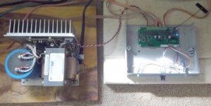
UPS was running late, as I've read their very busy during the pandemic - I got the quite massive linear power supply late last night.
I connected it up on my bench and did a quick regulation test. Initially set to 22V (adjustment from 21.5 to 29V) output dropped 100 mV with a 5.5A load. A pair for 2n3055s mounted to a large heatsink got hot quickly, from dissipating 100W at that load. The 33,000uf bulk cap was sitting at ~39V...
Ripple on the 22V output as measured with my DMM - I assume zero high frequency content - was better than 5mV at that load. So I connected it up to the amp - see photo.
In use at my casual listening level, the cases of the previously blistering hot 2n3055s are at room temperature. Ripple as measured with another DMM still better than 5 mV...
It sure isnt pretty nor elegant - more like ancient, well used and beat up - but does what I want sound wise. I assume this (analog regulated) is the electrically ideal AC input voltage source for this amp. $30 shipped is quite a bargain for US customers. The clarity of the sound I'm getting I assume is the best this amp is going to give. Cant wait for the opportunity to crank it to "show off the stereo" listening levels!
Attachments
Last edited:
I've tried it at 18.00v and also gave it a bit of a pounding while adjusting slowly up towards 25.5v 😀
At 18v I could clearly hear it when it ran out of "oomph", like hitting a wall. Much better at over 24v IMO.
Have not tried any higher than 25.5v, feel safer with just a tiny bit of safety margin there.
Looking forward to testing this thing properly.
At 18v I could clearly hear it when it ran out of "oomph", like hitting a wall. Much better at over 24v IMO.
Have not tried any higher than 25.5v, feel safer with just a tiny bit of safety margin there.
Looking forward to testing this thing properly.
Much better at over 24v IMO.
It's just a screwdriver away from moving the output up 3V to 25! I like some margin to absolute maximum ratings also...
When I worked at Intel, they had all these ridiculous voltages and tolerances just to run a processor - explicit, different rails sometimes just 50 mV apart! Maybe that's how these pure silicon things work best

Last edited:
My last Intel CPU was the Pentium 75! 😀
Those where the days, just a small passive black anodized heatsink. I could just up the numbers a bit in the bios to get it around P 90 performance I think it was, a bit unstable because of too much heat if I tried more than that.
Right now I am looking for some reasonably priced toslink to i2s interface, any and all tips are welcome.
BT is working well and the audio quality is quite good. And I do not think this would be a problem at all on smaller speakers, but my setup is quite sensitive, and when I turn the volume up on the AIO4CH, there is some noise when stopping and starting playback.
The unit has enough power for my needs, nice to have it all in a small convenient package. 🙂
lutkeveld, what about changing BT names on this thing? I need to know, because I am considering getting some more of these things for my daughters.
The noise has been fixed in the latest revision. The pop happened when playback is paused, the amp now mutes for 1 second during transition.
If you leave a note on your order I can change the BT name before shipping. Currently it is not possible to do it yourself.
If you leave a note on your order I can change the BT name before shipping. Currently it is not possible to do it yourself.
2 borads for stereo 2.1 pair?
Hi,
I just received my 2 AIO4CH boards and it looks very nice. PCBs, packaging, really great.
What I want to do with this setup is a stereo par of digital loudspeaker running from digital source (Raspberry Pi) over I2S. Two questions:
1. Is there any chance to use input I2S signal up to 96 / 192 kHz? What is limiting it to 48 / 44.1 kHz?
2. I have 2 AIO4CH boards and want to use them in 2x 2.1 setup (3 way stereo pair of speakers, each left and right channel with dedicated AIO4CH board in it). I don't plan to use AIO4CH volume control so I will "program" the crossover frequencies and EQ for each speaker separately (L, R). Now the question is how to "connect" left and right speaker - should I provide I2S input signal to both of them (some splitter from Raspberry to Left speaker I2S and right speaker I2S) or rather use eg Left speaker as a "master" and send data to right speaker ("slave") from it? (wired - I2S or wireless - Bluetooth TWS?)
Good to hear that you received your boards!
1) The DSP programs it runs limits the input to 48KHz sampling
2) In your situation I would recommend disabling the BT module (I have sent you a mail with instructions) and splitting the I2S input (data/wordselect/clock) from the Pi to the two modules. Use high quality cables and twist them for good data integrity.
Once you have verified it to work, you turn the amps on and leave them on max volume so that you can use your Pi to control the overal volume.
I see more people using I2S than I expected. I will try to make a more comprehensive guide soon on how to disable the BT module, how to hook up I2S and the commands you can use in the tool to check the amplifier status.
little advice: try to keep cables for I2S signals short. if you have a scope, check the quality of the signals on the AIO4CH boards after connection are done.
You can use one of the generic dt-overlays to generate I2S signals from RPi, for example
dtoverlay=hifiberry-dac
Just add this line to your config.txt file
If you wan to disable jack/HDMI audio output, comment the line
dtparam=audio=on -> #dtparam=audio=on
You can use one of the generic dt-overlays to generate I2S signals from RPi, for example
dtoverlay=hifiberry-dac
Just add this line to your config.txt file
If you wan to disable jack/HDMI audio output, comment the line
dtparam=audio=on -> #dtparam=audio=on
Good to hear that you received your boards!
1) The DSP programs it runs limits the input to 48KHz sampling
2) In your situation I would recommend disabling the BT module (I have sent you a mail with instructions) and splitting the I2S input (data/wordselect/clock) from the Pi to the two modules. Use high quality cables and twist them for good data integrity.
Once you have verified it to work, you turn the amps on and leave them on max volume so that you can use your Pi to control the overal volume.
I see more people using I2S than I expected. I will try to make a more comprehensive guide soon on how to disable the BT module, how to hook up I2S and the commands you can use in the tool to check the amplifier status.
Thanks for your quick feedback.
1) It seems that this TI chip supports up to 192 kHz. What is driving this 48 kHz please? I would like to use it for hi res audio up to 96 or 192 kHz. Any chance to enable this please?
2) my plan is to enable one speaker with Pi as a network streamer and I2S audio output to Zoudio (either directly Pi to I2S or Pi with SPDIF / USB to I2S convertor to Zoudio. As I2S is mainly for on the PCB interface between chip it will be ok for one this one speaker where Pi will be integrated. However for the second speaker the “distance” between Pi and Zoudio will be 2-3 meters which is probably not the best thing with I2S bus.
Does anyone uses 2x Zoudios for for left / right multiway speaker configuration? If sl how is the connection between them done?
1) The amplifier runs a 1.1 48K flow with parameters that can be modified by the configuration tool. Running at 192k requires custom software and makes it incompatible with the tool
2) If you want to use I2S, there are not much more options. I suspect that if you try to reduce the distance as much as possible and twist the cables, it will work fine. But its always good, as Darmur says, to check the signal quality at the other end if you have the tools to do so.
If you use BT as a source, you could use the TrueWirelessStereo function. If you use the analog input, you can split it.
Yes it does! (SBC/AAC/APT-X)
Other news:
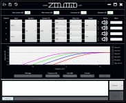
A new version of the configuration tool will be released next week.
The main improvement is a complete graphical overview of the filters.
A complete list of improvements will be published alongside the release of the software.

Other news:
A new version of the configuration tool will be released next week.
The main improvement is a complete graphical overview of the filters.
A complete list of improvements will be published alongside the release of the software.
Attachments
Last edited:
Could this psu work?
The 24v, 10a version:
https://powernet.fi/wp-content/uploads/2018/11/ADC50001.pdf
The 24v, 10a version:
https://powernet.fi/wp-content/uploads/2018/11/ADC50001.pdf
Could this psu work?
The 24v, 10a version:
https://powernet.fi/wp-content/uploads/2018/11/ADC50001.pdf
Well, yeah - it looks like someone wrote up a nice engineering spec for it, so there's some quality attributable to it. Trust but verify!
One thing they didnt mention was transient behavior; i.e. what happens when you put a current step on it. That's ~0A to, say, 3A in some number of A/us at some frequency.
I've no idea what Zoudio does input current wise when the music is going from silent to 1812 Overture levels with the volume up 80% of max; that would have to be measured. Perhaps the slugs of current it needs are nothing relative to what the switching power supply can provide.
I havent even had the chance to put an oscilloscope on the output of the PSU I'm using, while cranking up this amp. It certainly would be interesting to see if there's any voltage movement at all, or if it's jumping around by a few volts - enough to change my own PSU strategy.
Ever notice how PSU crazy some DIYAudio folks are, with the group buys on all sorts of designs? I assume there's a reason for that. Transient behavior, output impedance, stability, noise, AC line effects, efficiency / heat... Batteries start looking pretty good, unless you want continuous operation.
I've yet to try my amp with a 24V battery source. Beautifully galvanic isolated from everything! No stinkin' groundloops, nothing from the AC line / house wiring system to possibly interfere. I recall folks doing battery 30 years ago to achieve that, when the high end portable CD players came out.
It;s hard to say, w/o further investigation as to what's going on when you pair this amp with power supply X. The on board capacitors limit the transient input current to something reasonable, I'm sure. But that's about all you can say w/o an explicit, empirical look into it.
Thank you your thoughts on the PSU, I'll be picking one up today for ~40$, 2nd hand but allegedly never used, apparently they are quite pricy from new, around 175$.
I'm planning on building a workshop 2.1 stereo with two dayton exciter panels and a tang band T-line sub.
It'll be a while before I get it put together with the pandemic thing, but I'll post how the psu and amp part goes once I get all the parts.
I'm planning on building a workshop 2.1 stereo with two dayton exciter panels and a tang band T-line sub.
It'll be a while before I get it put together with the pandemic thing, but I'll post how the psu and amp part goes once I get all the parts.
Last edited:
- Home
- Vendor's Bazaar
- ZOUDIO AIO4CH: 4-channel amplifier with DSP and Bluetooth