Hi Tom,
Do you know what the input capacitance is of your board?
Reason I ask is I'm thinking of using it as a flat pre-amp to my "digital" RIAA preamp (using a PCM4222evm for A/D and a miniDSP-DI for the RIAA and rumble filters, digital out).
48K would be pretty much spot on loading my MM cartridge.
For now I have a AD8221 inamp board for that purpose, but going all differential could be a nice option.
Your boards come fully assembled (and tested I presume) which I really like, not much spare time, 3 small kids running around taking up a lot of time.
Also, maybe I missed it, but is there a formula for calculating the gain of the board with the gain set resistors (I need 17.3dB)?
And by any chance, are there measurements available with very small signals (55mV RMS @20KHz differential is about the theoretical maximum I expect from my cart) I will be feeding it.
Many thanks!
Do you know what the input capacitance is of your board?
Not precisely. A few pF probably. For use in a phono stage, I'd add 10 pF for a moving magnet setup.
Also, maybe I missed it, but is there a formula for calculating the gain of the board with the gain set resistors (I need 17.3dB)?
Yeah. I provide the equation in the design doc along with a bunch of resistor values for common gains.
And by any chance, are there measurements available with very small signals (55mV RMS @20KHz differential is about the theoretical maximum I expect from my cart) I will be feeding it.
I don't have such a measurement available at the moment, but can certainly add it to the list. I should be able to make some progress on improving my THD measurement capabilities this week as my other projects are waiting for boards and parts to arrive.
Tom
Hi Tom,
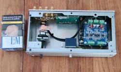
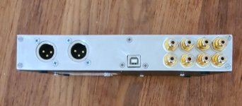
I've finished my preamp build and so far so good. Works great with absolutely no noticeable impact on sound/distortion etc.. I already had a dual TPS7A4700/A3301 power supply which is a perfect match at +-15V....
A wire with gain it is! Now starts the process of deciding on a nice enclosure...
I want to use another couple of UB's to improve the output of an existing ess9038pro dac which has a couple of electrolytic output caps. Does the UB eliminate any DC offset? Or what kind of DC offset is to be expected at the output of the UB?
Thanks!
Sander
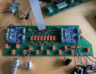
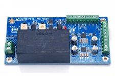
Here’s mine in testing.
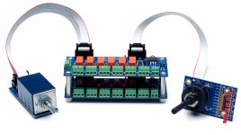
The basic setup is UB1 is used as the input buffer, six inputs with switching of the UB between balanced and SE depending on the input. UB1 drives the relay controlled volume circuit (in SE mode) before UB2 acts as the output buffer proving both SE and balanced outputs.
The basic setup is UB1 is used as the input buffer, six inputs with switching of the UB between balanced and SE depending on the input. UB1 drives the relay controlled volume circuit (in SE mode) before UB2 acts as the output buffer proving both SE and balanced outputs.
Attachments
Last edited:
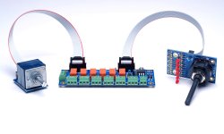
Very cool! Thank you for sharing. Meanwhile I'm working on this li'l project. I'll spin it into a fully differential preamp as well. I'll start a separate thread for that once the differential volume control is ready.
Meanwhile, you can find the input selector here: Input Selector – Neurochrome
and the rotary switch and volume control here: Selector Switch & Volume Control – Neurochrome
Tom
Meanwhile, you can find the input selector here: Input Selector – Neurochrome
and the rotary switch and volume control here: Selector Switch & Volume Control – Neurochrome
Tom
Attachments
...once the differential volume control is ready.
Can't say I have not thought "what if?"
I look forward to that one
Getting closer to a full preamp day by day. ")
The Preamp Power Supply will be in stock in about two weeks. Until then I'm running a preorder sale. ±12 V @ 650 mA.
Read all about it and buy yours here: Preamp Power Supply – Neurochrome
Tom
The Preamp Power Supply will be in stock in about two weeks. Until then I'm running a preorder sale. ±12 V @ 650 mA.
Read all about it and buy yours here: Preamp Power Supply – Neurochrome
Tom
Attachments
Tom, I've been playing with your buffer in my system and I notice that earlier in the thread you said that gain can be adjusted on-the-fly and I am wondering if also switching between inverted and non-inverted output is also feasible on-the-fly? All my inputs are single-ended. Perhaps it would work to wire the RCA Centre to both pin2 and pin3 on the inputs and use a switch to flick between the two relevant positions on the J3/J7 jumpers.
Now fully differential
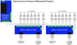
I added a Differential Volume Control board to my portfolio. It supports the 4-gang Alps "Blue Velvet" (RK271-series) volume pot. When combined with two Input Selector boards and one Selector Switch, you get a fully differential passive preamp. The two Input Selector boards are daisy chained in their connections to the Selector Switch.
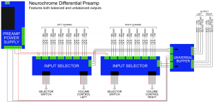
You can add a Universal Buffer if you'd like a buffered output. You then get both a differential and a single-ended output. You can use both at the same time if you wish.
I've shown my Preamp Power Supply in the wiring diagram for the passive balanced preamp. It may be a bit overkill in that application. After all, the only things that require power in the passive pre are relays and LEDs, so the power supply could be a 12 V wall wart. I would argue that a good power supply is needed if you wish to make the preamp buffered as shown in the second wiring diagram. The Preamp Power Supply is appropriate here.
Tom
I added a Differential Volume Control board to my portfolio. It supports the 4-gang Alps "Blue Velvet" (RK271-series) volume pot. When combined with two Input Selector boards and one Selector Switch, you get a fully differential passive preamp. The two Input Selector boards are daisy chained in their connections to the Selector Switch.
You can add a Universal Buffer if you'd like a buffered output. You then get both a differential and a single-ended output. You can use both at the same time if you wish.
I've shown my Preamp Power Supply in the wiring diagram for the passive balanced preamp. It may be a bit overkill in that application. After all, the only things that require power in the passive pre are relays and LEDs, so the power supply could be a 12 V wall wart. I would argue that a good power supply is needed if you wish to make the preamp buffered as shown in the second wiring diagram. The Preamp Power Supply is appropriate here.
Tom
Attachments
Last edited:
As I read the circuit this would not work as either pin2 or pin3 are grounded when used for SE input. I.e. if the RCA centre pit is connected to both it will always be connected to GND, whichever phase you choose on the header.Perhaps it would work to wire the RCA Centre to both pin2 and pin3 on the inputs and use a switch to flick between the two relevant positions on the J3/J7 jumpers.
Could of course be done with a DPDT switch (per channel).
I might well be wrong
Tom,
Can you power the input selector boards with 5V and then not populate your regulator and PS stuff on the board?
I was going to put the input selector in my DAC. Turntable is on the other side of the room. So I was putting a THAT driver board in the phono pre and running XLR to my DAC. The DAC is single ended so I was going to run the DAC through a THAT driver board, then connect it and the phono to a pair of input selector boards. I need two XLR outputs. Can I parallel the one outlet XLR connection to get two?
Hi Tom,
When using the UB at the output of the differential preamp, if we want to connect an unbalanced source, should we simply use IN+ and ground with IN- connected to ground or with a lowish ohm resistor to ground? Or the best scenario is another UB at the input?
Thanks
Do
When using the UB at the output of the differential preamp, if we want to connect an unbalanced source, should we simply use IN+ and ground with IN- connected to ground or with a lowish ohm resistor to ground? Or the best scenario is another UB at the input?
Thanks
Do
Can you power the input selector boards with 5V and then not populate your regulator and PS stuff on the board?
Sure.
I need two XLR outputs. Can I parallel the one outlet XLR connection to get two?
If you want two XLR outputs, you have two options:
- Use one UB and connect the balanced output to two XLR connectors.
- Use two UBs.
The drawback of option 2) is cost, though it does get you closer to my bulk discount thresholds...
Tom
- Home
- Vendor's Bazaar
- Universal Buffer achieving -140 dBc (0.00001 %) THD