Jean-Paul, IMHO you generalize strongly. :-(
At least as much -poorly designed- SS device has "coloration", irritating tone as tube ones.
BTW where are -in this case- noise and "coloration"?
https://www.diyaudio.com/forums/att...-dac-module-26-preamp-majestic-1-spectrum-jpg
Noise floor is high and distortion is high compared to good DS DACs - even
compared to PCM1704 it's pretty inferior.
TCD
I think you misunderstood my conversation with Jean-Paul.
This spectrogram is only the preamp (after the 1941).
Yes, my apologies, I thought it was pretty abysmal for a DAC.
TCD
Digital gain is about math. -2 or +2 dB is "the same thing". In the case of minus you are throwing away LSB "bits" and on plus, your have to suck in (LSB) bits - 1 bit for every 6 dB.
You do the math
I would say like this - even if you put it at 0 and think you have a bit clean conversion - think again as the filters are also math so everything is recalculated anyways before conversion compared to the CD record. If you like the sound then you are OK - no?
So + is no info loss but minus (attenuation) really is. Then you have the rounding errors for both directions in the math...
//
Last edited:
Well, I looked at it with an Oscilloscope while playing a sinus 1000hz 0db...full signal. With 0db you have a clean sinus, the more you add like +4 the more it does not look like a sinus anymore, becomes more a non symetrical triangle.
Different question:
I am reading always about transients in a music signal like the strike of a drummer etc can create impulses which are like 16db bigger than the musical signal...well what does mean in terms of Vpp-Envelope really ? What I mean: When I play a sinus digital 0db, so full digital signal: And I measure this with an osci: Is this the biggested technical possible analog signal the DAC can send to whatever comes next ? Or can those transients become even bigger than that ?
I apologize in advance for the dumb question.
I have a dam1941 that is built up with the Soekris power supply, user display and output buffer. It is working fine.
I want to add a headphone amp. I have the headphone amp but am not sure where to connect it so that it is controlled by the output switch on the user display board (S4) and the volume is controlled by the rotary encoder. I have looked through the manual and this thread but can't seem to find the answer.
Thanks for assisting me.
I apologize in advance for the dumb question.
I have a dam1941 that is built up with the Soekris power supply, user display and output buffer. It is working fine.
I want to add a headphone amp. I have the headphone amp but am not sure where to connect it so that it is controlled by the output switch on the user display board (S4) and the volume is controlled by the rotary encoder. I have looked through the manual and this thread but can't seem to find the answer.
Thanks for assisting me.
First you need an amplifier to drive the headphones.
Phones are then active when EN_PHO, J13 pin 4 is active high, Line then active when EN_LIN, J13 pin 3 is active high. It's designed to use CMOS relays for switching, just like a dac1541/dac2541, but you can also use mechanical relays with a relay driver.
J13 pin 1 & 2 is then used to control the amplifier gain, to optimize S/N.
is there a CAD drawing for the 1941 that I can give to water jet cutting service for a case for this board?
There are this one, sorry, no fancy 3D drawing.
Attachments
First you need an amplifier to drive the headphones.
Phones are then active when EN_PHO, J13 pin 4 is active high, Line then active when EN_LIN, J13 pin 3 is active high. It's designed to use CMOS relays for switching, just like a dac1541/dac2541, but you can also use mechanical relays with a relay driver.
J13 pin 1 & 2 is then used to control the amplifier gain, to optimize S/N.
Thanks, that's helpful. I understand about using J13 pin 4 to control the headphone amp but don't quite follow the use of J13 1 & 2 to control amp gain. Some experimentation required...
connection display board via cable
thanks for showing your project, very nice build!
may I ask you regarding your realisation of the connection between DSP- and display board? which cable did you use ? do you have a parts number?
I have also the plan to connect the display board via a cable but was not able to find it at mouser, digi etc.
Many thanks and Regards
Werner
Hello pecci,And this is my just finished dam1941, with Salas triplet too and display board (short version, w/o headphone and volume section).
thanks for showing your project, very nice build!
may I ask you regarding your realisation of the connection between DSP- and display board? which cable did you use ? do you have a parts number?
I have also the plan to connect the display board via a cable but was not able to find it at mouser, digi etc.
Many thanks and Regards
Werner
may I ask you regarding your realisation of the connection between DSP- and display board? which cable did you use ? do you have a parts number?
I have also the plan to connect the display board via a cable but was not able to find it at mouser, digi etc.
I think any 20 pin Flat Ribbon Cable like this will do
Many thanks for the help!I think any 20 pin Flat Ribbon Cable like this will do
with the info you provided I found a fitting cable also at digi.
Hi,
That cable and connectors are ok, but in that case you must first solder 2x10 male pins header (straight but better angled) on DSP board.
Actually on that side I use connector from attached photo, mount flat ribbon cable by press fit and solder them from underside (watch out for correct pinout)
I find them at local store and sorry haven’t any Mouser or DigiKey ref no.
Br
Attachments
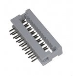
You can find that connector on:
RS PRO 20-Way IDC Connector Plug for Cable Mount, 2-Row | RS Components
2 Row IDC Transistion Plug/Socket for Ribbon Cable - Various Pins/QTYs UK Seller | eBay
Use bench vice for firm press fit on ribbon cale but on one side add some spacers to protect header soldering pins
Best regards
RS PRO 20-Way IDC Connector Plug for Cable Mount, 2-Row | RS Components
2 Row IDC Transistion Plug/Socket for Ribbon Cable - Various Pins/QTYs UK Seller | eBay
Use bench vice for firm press fit on ribbon cale but on one side add some spacers to protect header soldering pins
Best regards
Be extremely cautious with the resistance of the strip cable! I also tried with a piece of cable from the drawer. It did not work, the display was half bright and all segment lit. I thougth I burnt the ICs when soldered but after many attempts of resoldering, troubleshooting I was unsuccesful. But i connected the control panel to the main board and then everything was OK. Then I decided to prepare a strip cable from individual wires with appr. 0,8mm diameter and voila it started to work properly. My distance is appr 20cm between the 2 panels.
- Home
- Vendor's Bazaar
- dam1941 - Next Gen Discrete R-2R Sign Magnitude 24 bit 384 Khz DAC module