I'm absolutely not doubting the necessity for headroom in a system. Nor am I arguing that the OPA1622 will drive every headphone ever made to reference levels. Rather, I am saying that the OPA1622 can drive most headphones, including low sensitivity planar types such as the HE-6, HE-500, and HE-560 to extremely loud levels. And at very low distortion (no 1% THD caveats in these calcs), attached is an FFT of the OPA1622 output at 150mW into a 32 ohm load, still below its onset of clipping, and no bridging or parallel amplifiers required. This same amount of current would drive the HE-560s on my desk to 113.2 dB, and that's good enough for me ")
Attachments
understanding the real implications of most "sounds good to me" examples benefits from dissection, comparison with EE, Psychoacoustics, recorded music signal properties all together
rare clips of transient peaks are hard to hear without AB/X immediate reference, clipping tones generates audibly obnoxious distortion
of course you can find some audiophile critics claiming minutes of a performance was spoiled for them after a single clipping event in the recording/playback
much dynamic range compressed music, hit with the "loudness war" ugly stick looks like its nearly continuously clipping as source - many speculate this further desensitizes modern listeners to clipping
severe dynamic range compressed shouldn't be played at over 80 dB for all day long listening - and you may not need even 10 dB of headroom above the average
but some live acoustic music does produce "high" SPL dynamic peak levels at the listening position
another question - do we ever see waveforms of current clipping - nice that things recover politely from hitting the V rails - but what about output protection/current limit/starvation?
Last edited:
confused here, can you confirm what you mean. THX calls for 85dB at -20dBFS for mains and 10dB more for subs (at listening position). So do you mean that the combined blart of all 6 or 7 or 9 or whatever speakers can peak at over 115dB?Home Theater THX calls for 85 + 20 = 105 dB for mains, + 10 dB more for sub-bass LFE
with all channels blasting, peaks over 115dB SPL are Standard in a THX calibrated Home Theater setup
THX reference level explained - Acoustic Frontiers
individual mains speakers are calibrated for digital full scale = 105 dB SPL at the listening position
85 dB SPL is the "0 dB" volume control setting, you can dial it up, dynamic peaks are expected to be above
the LFE channel is supposed to have an additional +10 dB max capability
the LFE 115 dB SPL certainly dominates, 5x 10⁵ db mains does add to 112 dB if linearly summed, adding less than 2 dB to the 115 dB of the LFE
Last edited:
So I'm not sure how you determined that the OPA1622 could not drive them above 90dB?
You are right, I should have said "going significantly over 90dB SPL..." - my quick spreadsheet plug-in was 120dB SPL for both, attached below. I've used 120dB as a design target for so long it is just sort of second nature.
Good to hear that the chip stays out of thermal trouble for the higher voltage rails/swings with the larger loads.
Hey I have one more OPA1622 question about wiring two or more 1622's up in parallel for more current output, similar to what NwAvGuy did with his O2 headamp. He used 1R balancing resistors on the outputs of the two parallel op-amps (0.5R total Z looking back into the amp). I know the DC balancing currents flowing between the chips can/will affect the class AB bias in the output stage to some degree. Is there a recommendation on an output balancing resistor value for 2 (or 4) OPA1622's in parallel that would cause minimal problems with the chips? If I could parallel two OPA1622s to double the output currrent and spread the chip dissipation I think the chip would start getting interesting to me. Thank you!
Attachments
Last edited:
I agree a series output resistor wrecks the damping factor and often introduces additional distortion due to the non-linear current drawn by the headphones. I wrote an article on an alternate compensation method for headphone amplifiers in diff amp configurations to avoid this: http://www.ti.com/lit/an/slyt630/slyt630.pdf
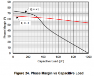
For this exact reason, we designed the OPA1622 to be very stable into capacitive loads without a series resistor. This is shown in Figure 24 in the datasheet, which plots phase margin vs. capacitive load for G = +1 and -1 configurations (reposted here for convenience). In a gain of -1 the OPA1622 has 54 degrees of phase margin with a 1nF capacitive load and no series isolation resistor.
I'm not a big fan of overshoot vs cap load graphs. They make a lot of assumptions about the op amp's compensation in order to correlate overshoot to stability. I would rather cut to the chase and see the phase margin of the system to know if it's stable.
Series balancing resistors are really limited by the amount of DC circulating current between the outputs that is acceptable. The maximum input offset of this part is +/-500uV. So if we had two parts in gains of +1, the maximum output offset that is theoretically possible would be 500uV x 2 = 1mV (500uV is a 6 sigma number btw, so the odds of getting two at the max in opposite directions is like winning the lotto). If you had 1mV offset divided by 2 ohms of balancing resistance that's 500uA of DC circulating current. Probably no big deal.
I haven't played with putting OPA1622's in parallel yet to see how far I can push those balance resistors down.
Attachments
Thanks for the quick reply!
You saw my post before I edited out the capacitive load stuff. I had that written up, then went back through the datasheet and saw the ">600pF drive" at the top and deleted that section. For folks that didn't see the before-edit on my post, I was asking about Cload capability. I hadn't seen the usual section on the OPA1622 datasheet about driving capacitive loads and (usually) adding series output resistor for isolation. Which is of course an audio problem because the resistor messes with the damping factor. I usually add 1 to 2.2nF these days on my output test loads to simulate cable and driver capacitance. I also hadn't found the typical graphs of step resposnse peaking for various output Cloads.
Your article looks very interesting! I will give that a read tonight. I was impressed to find that Cload was mentioned right at the top of the sheet and that the typical application circuits shown didn't include any output series resistor. You guys clearly understood the market requirements for the chip.
Ah so the Cload is on a phase margin graph. That is a clever way to do it! And useful. So margin hits the magic 30 degrees left at 600pF, but this is with non-inverting. One of the headamp projects I have posted on the forum here is inverting in both stages, the gain and the (-unity) buffer stage. With the OPA1622 in an inverting buffer config it is good to go way on out there, past my 1nF typical load. Sweet!
Thanks for the balance resistor guidance! In one amp project here I have 6 NJM4556A sections (3 dual op-amps) in parallel. While designing it I tested a pile of 40 of the things and found, interestingly enough, that not only were the offsets well grouped in the 2.5 - 3.5mV range, they were all positive! Every one. With that information I wasn't too concerned about balancing so many. Like you say, the odds of getting a -3.5mV after that large of a sample size would be like winning the lotto. Hmmm.... I may whip up a board for fun with some parallel OPA1622s.
Thank you again for the help and information!
You saw my post before I edited out the capacitive load stuff.
I had that written up, then went back through the datasheet and saw the ">600pF drive" at the top and deleted that section. For folks that didn't see the before-edit on my post, I was asking about Cload capability. I hadn't seen the usual section on the OPA1622 datasheet about driving capacitive loads and (usually) adding series output resistor for isolation. Which is of course an audio problem because the resistor messes with the damping factor. I usually add 1 to 2.2nF these days on my output test loads to simulate cable and driver capacitance. I also hadn't found the typical graphs of step resposnse peaking for various output Cloads.Your article looks very interesting! I will give that a read tonight. I was impressed to find that Cload was mentioned right at the top of the sheet and that the typical application circuits shown didn't include any output series resistor. You guys clearly understood the market requirements for the chip.
Ah so the Cload is on a phase margin graph. That is a clever way to do it! And useful. So margin hits the magic 30 degrees left at 600pF, but this is with non-inverting. One of the headamp projects I have posted on the forum here is inverting in both stages, the gain and the (-unity) buffer stage. With the OPA1622 in an inverting buffer config it is good to go way on out there, past my 1nF typical load. Sweet!
Thanks for the balance resistor guidance! In one amp project here I have 6 NJM4556A sections (3 dual op-amps) in parallel. While designing it I tested a pile of 40 of the things and found, interestingly enough, that not only were the offsets well grouped in the 2.5 - 3.5mV range, they were all positive! Every one. With that information I wasn't too concerned about balancing so many. Like you say, the odds of getting a -3.5mV after that large of a sample size would be like winning the lotto.
Hmmm.... I may whip up a board for fun with some parallel OPA1622s. Thank you again for the help and information!
Thanks for the kind words, we really looked closely at headphones as an amplifier load during the development process. At one time my entire desk was covered in headphones that were either about to have their impedance measured, or had already been measured. When we wrote this blog we included a just few of the curves: Amp up your cans: Is your op amp stable? (Part 2) - Precision Hub - Blogs - TI E2E Community
From those measurements, I built a passive component model of a headphone for the IC designers to use for all simulations. I also looked very closely at switching power supplies and made an output impedance model of those for the IC designers to use in distortion simulations. They got pretty annoyed by that Anyone can hit great numbers in simulation with ideal power supplies, but add some impedance to those rails and it can all fall apart!
Also, since it was mentioned before, I thought I would point at that the OPA1622 is rated for a continuous short circuit at the output. As was pointed out by JCX, shorts are very common when plugging/unplugging a TRS jack so robust short circuit current protection and thermal shutdown was a must-have.
I look forward to seeing your project! Parallel OPA1622s could make a beast of an amplifier. Last night after typing out that response I started to think about a headphone amp with both sections of an OPA1622 in parallel, and inside the feedback loop of an OPA827 In fact, I believe there is a TI employee in Dallas putting A LOT of OPA1622s in parallel in a similar approach to Douglas Self's massively paralleled NE5532 amplifier.
A balanced headphone output with the OPA1622 could be really interesting because if you look closely at the FFTs of the OPA1622 outputs at lower power levels, the even harmonics are dominant and might cancel in a balanced configuration.
It's been very exciting for me see people use this chip in their projects even though the package isn't the most DIY friendly.
From those measurements, I built a passive component model of a headphone for the IC designers to use for all simulations. I also looked very closely at switching power supplies and made an output impedance model of those for the IC designers to use in distortion simulations. They got pretty annoyed by that
Anyone can hit great numbers in simulation with ideal power supplies, but add some impedance to those rails and it can all fall apart!Also, since it was mentioned before, I thought I would point at that the OPA1622 is rated for a continuous short circuit at the output. As was pointed out by JCX, shorts are very common when plugging/unplugging a TRS jack so robust short circuit current protection and thermal shutdown was a must-have.
I look forward to seeing your project! Parallel OPA1622s could make a beast of an amplifier. Last night after typing out that response I started to think about a headphone amp with both sections of an OPA1622 in parallel, and inside the feedback loop of an OPA827
In fact, I believe there is a TI employee in Dallas putting A LOT of OPA1622s in parallel in a similar approach to Douglas Self's massively paralleled NE5532 amplifier. A balanced headphone output with the OPA1622 could be really interesting because if you look closely at the FFTs of the OPA1622 outputs at lower power levels, the even harmonics are dominant and might cancel in a balanced configuration.
It's been very exciting for me see people use this chip in their projects even though the package isn't the most DIY friendly.
In fact, I believe there is a TI employee in Dallas putting A LOT of OPA1622s in parallel in a similar approach to Douglas Self's massively paralleled NE5532 amplifier.
Like this?
http://www.diyaudio.com/forums/headphone-systems/237041-massively-parallel-lme49990-headamp.html
The idea was 8 LME49990's per channel in parallel. I never made it to finishing & fabricating that one. Too much soldering! By the end of the thread some folks were suggesting the toaster oven and paste method.
In looking at the open loop gain/phase plot in your blog article I can see that you guys really tinkered with the chip to maximize it for the audio band. Looks fantastic!
Last night after typing out that response I started to think about a headphone amp with both sections of an OPA1622 in parallel, and inside the feedback loop of an OPA827.
I like it! This one of mine uses an 827 looped around a LME49600 on each channel:
http://www.diyaudio.com/forums/headphone-systems/244473-o2-headamp-output-booster-pcb.html
Looping the 827 around the paralleled 1622 would result in the same maximum output current, but should be lower THD.
Yeah it is amazing how well things work with ideal voltage sources as the power supply! Good for you in insisting on consideration of real-world power supply output Z. I've avoided switchers like a sore foot, always use linear, but there probably is no good reason for that anymore with switching frequencies up near/over a MHz.
Last edited:
when paralleling another opportunity is to bias the outputs against each other - giving a region of push-pull Class A operation
even if not strictly needed given the performance of the OPA1622 - Class A operation makes power supply and return path currents Linear, instead of AB where they look half wave rectified
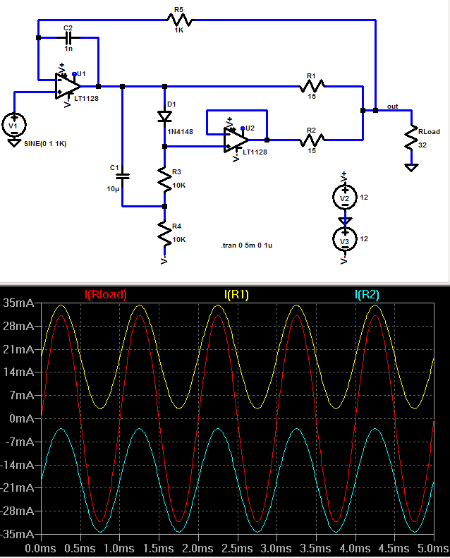
just a sim, but I have done similar with the TPA6120, lower Vos, lower current summing R, still can use a good FET input op amp giving feedback around the output to reduce the R effects on output Z
even if not strictly needed given the performance of the OPA1622 - Class A operation makes power supply and return path currents Linear, instead of AB where they look half wave rectified
just a sim, but I have done similar with the TPA6120, lower Vos, lower current summing R, still can use a good FET input op amp giving feedback around the output to reduce the R effects on output Z
Last edited:
It's not apparent how/why wrapping an OPA827 around the OPA1622 would improve matters.
I like using the OPA164x or OPA827 after a volume control pot because they're basically devoid of common-mode distortion effects. And if I have to throw another op amp in the signal path, I might as well wrap the OPA1622 into the feedback loop and take advantage of the additional loop gain. It would require a careful look at stability of course.
when paralleling another opportunity is to bias the outputs against each other - giving a region of push-pull Class A operation
even if not strictly needed given the performance of the OPA1622 - Class A operation makes power supply and return path currents Linear, instead of AB where they look half wave rectified
just a sim, but I have done similar with the TPA6120, lower Vos, lower current summing R, still can use a good FET input op amp giving feedback around the output to reduce the R effects on output Z
That's really interesting idea, I might have to play around with this in the lab a bit.
I like using the OPA164x or OPA827 after a volume control pot because they're basically devoid of common-mode distortion effects.
That is exactly why I used the (FET input) OPA827 in the project linked. The amp it plugs into as an alternate output buffer board in a pot-in-the-middle headamp design with a coupling cap on the wiper. I wanted FET-input after the pot to minimize the input bias current induced ground-return resistor IR offset voltage. Plus the specs on the chip did sound like it would be good to minimize CM (non-inverting design in that one). The 827 also has very low output offset. I was shooting for an output offset voltage less than 200uV from the buffers. The 827 delivered with a typical measured of around 80uV. In fact, if the OPA1622's offset is 500uV, the looped 827 would improve on that too.
Yeah it would be interesting to see what happens with the phase margin for OPA827 + 2x OPA1622.
Last edited:
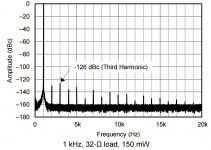
I'm absolutely not doubting the necessity for headroom in a system. Nor am I arguing that the OPA1622 will drive every headphone ever made to reference levels. Rather, I am saying that the OPA1622 can drive most headphones, including low sensitivity planar types such as the HE-6, HE-500, and HE-560 to extremely loud levels. And at very low distortion (no 1% THD caveats in these calcs), attached is an FFT of the OPA1622 output at 150mW into a 32 ohm load, still below its onset of clipping, and no bridging or parallel amplifiers required. This same amount of current would drive the HE-560s on my desk to 113.2 dB, and that's good enough for me
John
I understand that the THD is very low, but does the large number of harmonics in the graph concern you (I could see up to the 19th)? Is that crossover distortion? Would an amp with somewhat higher distortion but far fewer harmonics sound any better?
Last edited:
John
I understand that the THD is very low, but does the large number of harmonics in the graph concern you (I could see up to the 19th)? Is that crossover distortion? Would an amp with somewhat higher distortion but far fewer harmonics sound any better?
Huh they are at around or better than 140dB below the fundamental... the noise from the source would probably dominate.
John
I understand that the THD is very low, but does the large number of harmonics in the graph concern you (I could see up to the 19th)? Is that crossover distortion? Would an amp with somewhat higher distortion but far fewer harmonics sound any better?
Consider the scale and noise floor of the FFT though. Most of those harmonics are under -140 dBc! If I had done the standard 32768 pt FFT on a SYS-2722, we'd probably only see up to the 5th harmonic. We tend to assume that if harmonics are below the noise floor of the FFT, then they don't exist. But I can make the noise floor of an FFT whatever I want, just by changing the bandwidth, number of points/bins, and averaging. Fourier series are infinite summations, so although an amplifier's 2nd or 3rd harmonic may dominate, there are still likely higher ordered harmonics present.
As for the exact source of the harmonics, there's always multiple sources. The design of the output stage of the OPA1622 really minimizes crossover distortion, but being a class-AB output stage it's never completely eliminated. Also, the beta of the output transistors is dependent upon current density (IC) and VCE, so their transfer functions are constant changing with output current and output voltage. We actually plotted the gain of the output stage vs. output voltage of the OPA1622 in this blog post: Amp up your cans: Distortion in headphone amplifiers (part 4) - Precision Hub - Blogs - TI E2E Community
John
Do you think the OPA1622 is as good as we'll ever need for driving headphones? Can you see any way of improving it further, maybe going Class A output stage in a larger package that could be heat sinked?
It better not be "as good as we'll ever need" or I'm out of a job! I think we made a good product, but I'm not going to quit now
I do see us making additions to the OPA162x product family in the future. We'll definitely look at higher output current versions, which may also require other package options. Frankly, a Class-A output version is probably not in the cards since the customer base for such a product would be pretty limited. But you could always bias the output into class-A if you wanted.
- Home
- Vendor's Bazaar
- New Audio Op Amp - OPA1622