Scott, thanks very much! That sounds like a simple and fun way to get the job done. Amazon sells some temperature controlled hot plates for about USD 250 and upward. But I decided to put together my own rig-of-the-merde instead, using
this $15 hotplate
and
this $39 temperature controller.
I hope they work together sufficiently well to approximate a purpose built temperature controlled hot plate, and to solder EPAD devices. If so, big money has been saved. DIY tinkering enjoyment has also occurred!
Amazon talked me into purchasing an optional accessory, not because it is needed, but instead because it looks like FUN: a $14 non-contact (laser) thermometer
I have a preheat plate and use a blower once preheated. The preheat plate is simply a slab of 10mm aluminium with some high-watt resistors attached - actually it was going to be a hot bed for a 3D printer but something better took its place.
You will find the thermal mass of the plate will be quite large that you can even control the temperature manually quite easily. I just flick the supply on, wait for it to come up to the soak temperature, start working the hot air, switch off the supply and continue working.
Well I ordered a bunch of these from TI and have implemented a headphone amp using one. The source is a ES9018 going into a CS3318 in configuration using 4 channels of the CS3318. This then feeds into a differentially configured OPA1622 driving HD650s.
My previous set up was exactly the same except a TPA6120 filled the role of the OPA1622. All I can say is that the OPA1622 sounds sublime and measures like a champ.
Aural memory is rubbish but do I think this sounds better? Yes. Noise performance is better (in part due to the OPA being more tolerant of resistor values), distortion measures slightly lower but we're talking about vanishing vs vanishing levels anyway, the OPA1622 has vastly superior PSRR and no need for output isolating resistor. There are technical reasons for it to sound better.
Either way use with confidence 🙂
Well I ordered a bunch of these from TI and have implemented a headphone amp using one. The source is a ES9018 going into a CS3318 in configuration using 4 channels of the CS3318. This then feeds into a differentially configured OPA1622 driving HD650s.
My previous set up was exactly the same except a TPA6120 filled the role of the OPA1622. All I can say is that the OPA1622 sounds sublime and measures like a champ.
Aural memory is rubbish but do I think this sounds better? Yes. Noise performance is better (in part due to the OPA being more tolerant of resistor values), distortion measures slightly lower but we're talking about vanishing vs vanishing levels anyway, the OPA1622 has vastly superior PSRR and no need for output isolating resistor. There are technical reasons for it to sound better.
Either way use with confidence 🙂
Wow, it's really great to hear such positive feedback on the OPA1622.
Considering the amount of time I spent working with the designers (and staring at my ceiling at night wondering if we had made all the right decisions) it's very humbling to know that there are finally people enjoying music through it.
Thanks John. For over a decade the TPA6120 had been my go to device for either driving headphones or as an indestructible line driver. It's price was always attractive too which was a nice plus but it wasn't without it's limitations. The OPA1622 basically does the same thing but better, is far more flexible, requires less board space and fewer supporting components.
The enable feature is very nice too especially the attention to its pop free nature but in my application the device does produce a rather noticeable pop into the 600ohm phones upon power down and a very faint one on power up. This might be entirely normal but I worry that when working as a line driver into a power amps (with appreciable gain) that loudspeakers might not be too fond of it. Still I might be worrying over nothing.
The pop on power down is surprising to me, unless your power supplies have very different slopes when powering down. Are you controlling the enable pin with some external logic or does it just have a pull-up resistor? If possible try to bring the enable pin low (VEN < 0.7V ish) before the supplies drop to the minimum supply voltage of the op amp (+/-2V). One way to hold the pin low on power up and down is by using a voltage divider. I talk about this on page 18 of the datasheet.
The pop on power down is surprising to me, unless your power supplies have very different slopes when powering down. Are you controlling the enable pin with some external logic or does it just have a pull-up resistor? If possible try to bring the enable pin low (VEN < 0.7V ish) before the supplies drop to the minimum supply voltage of the op amp (+/-2V). One way to hold the pin low on power up and down is by using a voltage divider. I talk about this on page 18 of the datasheet.
I am actually talking about powering the chip down with the enable pin, sorry I wasn't clear there. I am controlling it with a micro but when turning the device on and off, with it driving headphones directly there is a larger than expected pop.
Does the mode of operation matter or power supply rails? I'm using a standard 3.3v micro, 8 volt power rails with the device configured differentially. 1k resistors are in the inverting input feedback path and non inverting path to ground with 1.8k used on the inputs from the signal source giving a gain of ~0.5 is the device comfortable operating at gains lower than unity?
Last edited:
There's nothing wrong with that implementation. Signal gain's lower than unity are still greater than unity from a stability standpoint as it is determined by the noise gain (1+ RF/RG).
This is a bit of a head-scratcher for me. I would be really interested to see an oscilloscope screenshot of the enable pin voltage and the output voltage when the enable pin transistions low, if you have that ability. Are you also doing anything to the DAC when you power down the OPA1622? Any clicks or pops from the DAC will travel around the feedback network of the OPA1622 when the device is powered down.
This is a bit of a head-scratcher for me. I would be really interested to see an oscilloscope screenshot of the enable pin voltage and the output voltage when the enable pin transistions low, if you have that ability. Are you also doing anything to the DAC when you power down the OPA1622? Any clicks or pops from the DAC will travel around the feedback network of the OPA1622 when the device is powered down.
Okay so I've had a bit more of a play with this. First of all I get a 2.5V voltage spike when the opamp is turned off and a 1V voltage spike when it is turned on.
I also managed to get my 16 channel board build, with 8 OPA1622s so now I have a much bigger sample size with which to experiment with.
7 of those 8 display absolutely spec sheet performance with very little pop on the output. The 16 channel board uses the opamps in a single ended unity gain configuration with the inverting input tied to the output. What a useful feature on the pinout having the inverting input next to the output pin!
The last device however exhibits a much larger transient, just like the one used in the headphone amplifier section.
Both exhibit another unusual property though in that they start to show an increase in distortion beyond around 0.6Volts on the output and the single ended configured device shows some DC offset when powered down. The level of DC offset is dependent on the load resistance it is connected to.
The odd thing is that apart from the described issues above they actually measure just as well as the others with extremely low distortion and very low noise.
Is it possible that I've damaged them during the soldering process? This is the only thing that I can think of and at least it would explain why I'm having issues. Maybe some of the transistors have been damaged and are leaking a bit of current or something?
The other possibility I could think of is an assembly issue, for example the thermal pad on the IC not having a good connection to the negative supply. It's interesting to me that it's always both amplifiers in the package rather than just 1 of the 2 channels with the issue.
The other possibility I could think of is an assembly issue, for example the thermal pad on the IC not having a good connection to the negative supply. It's interesting to me that it's always both amplifiers in the package rather than just 1 of the 2 channels with the issue.
Thanks for that Jon that is definitely something I can look into and yes with my small sample size it's always both doing exactly the same thing at the same break points as it were. It would be odd if something internal failed identically in each channel unless some common circuitry is shared between the channels, or if the same thing in each channel had been completely destroyed ie went open circuit or became a short.
Yes, problem solved!
It seems like it was a bad connection to one pin or another. The VSON package is quite hard to handle and even with a magnifier it's hard to sometimes verify if continuity is present. I much prefer thermally enhanced 10 pin MSOP packages where a more compact solution is wanted.
I doubt it was the pad as this is the first thing I soldered to align and mount the chip to the PCB. It could have been the -ve voltage pin or ground pin but I'd figure that all kinds of things would function incorrectly if the ground pin was left unsoldered. Either way, success and now the turn on and off pops are completely inaudible.
Awesome op amp! I too have implemented a rough amp design with this guy and it sounds amazing!
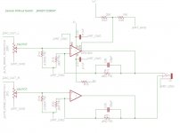
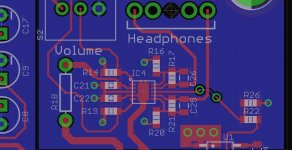
Just about to send out a next revision, John - could I get some feedback and your thoughts on this schematic/layout? In your opinion do I need a separate input and gain stage here or is it OK to use the OPA1622 as both gain (gain of +2 in this case) and output stage? Currently I've got +-5V power supply rails, and it is being fed by a PCM5102A DAC (2.1VRMS output) with a 10k pot in between the DAC and the OPA1622.
Thanks,
Connor
Attachments
Awesome op amp! I too have implemented a rough amp design with this guy and it sounds amazing!
Just about to send out a next revision, John - could I get some feedback and your thoughts on this schematic/layout? In your opinion do I need a separate input and gain stage here or is it OK to use the OPA1622 as both gain (gain of +2 in this case) and output stage? Currently I've got +-5V power supply rails, and it is being fed by a PCM5102A DAC (2.1VRMS output) with a 10k pot in between the DAC and the OPA1622.
Thanks,
Connor
It's really up to you, from a distortion and stability standpoint gain of 2 is fine for the OPA1622. And bonus points for matching source impedances at the op amp inputs when the potentiometer wiper is at 50%! However, you are making a bit of a sacrifice in terms of total system noise. The large value resistors will contribute some thermal noise to the system, although the DAC noise may dominate here. And at different pot settings (not 50%) your DC offset at the output will vary. You might want to consider AC coupling between your pot and the 3.32k resistor.
Personally, I would put an OPA1642 (or OPA2140 for lower offsets: less click/pop) after the volume control because it doesn't exhibit common-mode distortion effects with high source impedances and configure it in a gain of two and then use the OPA1622 in a gain of 1 for the output. The OPA1688 and OPA1652 are also alternatives to the OPA1642. But that does mean adding another op amp, and I understand the less is more approach 🙂
5th Element: I'm so glad you got it figured out! Your issue had been on my mind the last few days wondering if there was something in your application that I had missed! I hope it gives you lots of enjoyable listening time now!
It's really up to you, from a distortion and stability standpoint gain of 2 is fine for the OPA1622. And bonus points for matching source impedances at the op amp inputs when the potentiometer wiper is at 50%! However, you are making a bit of a sacrifice in terms of total system noise. The large value resistors will contribute some thermal noise to the system, although the DAC noise may dominate here. And at different pot settings (not 50%) your DC offset at the output will vary. You might want to consider AC coupling between your pot and the 3.32k resistor.
Personally, I would put an OPA1642 (or OPA2140 for lower offsets: less click/pop) after the volume control because it doesn't exhibit common-mode distortion effects with high source impedances and configure it in a gain of two and then use the OPA1622 in a gain of 1 for the output. The OPA1688 and OPA1652 are also alternatives to the OPA1642. But that does mean adding another op amp, and I understand the less is more approach 🙂
Thanks for the quick response John. I was planning on going with a pair of 1k resistors to get the needed gain of +2 with a lower thermal noise, but I was worried about the load this would put on the PCM5102A with the bias resistor being lower than 1k (around 550 ohm pulldown on the non inverting input as 550||5000 gets pretty close to canceling out the DC offset effects of the 1k gain resistors). Trying to avoid having to AC couple the inputs, I like not having to stick expensive capacitors in the signal path 🙂 Do you think a 550ohm pulldown would be a bit too stiff for the DAC to drive? Couldn't find any current output specs for the PCM5102A DAC...
They specify a minimum load impedance of 1kOhm in the PCM5102 datasheet, so best to keep it above that.
Ordered some boards
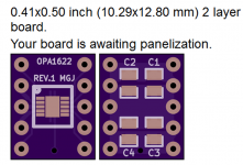
I sent off my rev.1 PCB design to OSH Park today. It's intended to be hand assembled, and applies a rude and unholy strategy of maximum complexity: SMD parts on both top side and bottom side, plus through hole attachment of the I/O pins.
Same pinout ordering as the SMD OP1622 except expanded to a 10 pin, 300 mil, Dual Inline Package. It mates with a standard 10 pin DIP socket like this one.
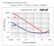
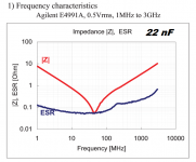
On the little daughter card, each supply has two 0805, X7R, 100V bypass capacitor: 100nF and 22nF. Impedance plots attached below. Why 100V? Because its dC/dV is lower.
I have no idea how many revisions will be required to get it working and make the soldering task easier. One revision? Doubtful.
_
I sent off my rev.1 PCB design to OSH Park today. It's intended to be hand assembled, and applies a rude and unholy strategy of maximum complexity: SMD parts on both top side and bottom side, plus through hole attachment of the I/O pins.
Same pinout ordering as the SMD OP1622 except expanded to a 10 pin, 300 mil, Dual Inline Package. It mates with a standard 10 pin DIP socket like this one.
On the little daughter card, each supply has two 0805, X7R, 100V bypass capacitor: 100nF and 22nF. Impedance plots attached below. Why 100V? Because its dC/dV is lower.
I have no idea how many revisions will be required to get it working and make the soldering task easier. One revision? Doubtful.
_
Attachments
Last edited:
John, could you comment on how the OPA1622 compares with the LME49600 ?
The OPA1622 dataheet specs. look very impressive!
regards,
Rick
The OPA1622 dataheet specs. look very impressive!
regards,
Rick
John, could you comment on how the OPA1622 compares with the LME49600 ?
The OPA1622 dataheet specs. look very impressive!
regards,
Rick
It's really an apples to oranges comparison. The LME49600 and BUF634 are essentially just the output stage of an amplifier. They are able to deliver very large amounts of current but also require fairly large packages to dissipate heat. Intrinsically, they have not-insignificant distortion, which is why all all of the distortion measurements in the LME49600 datasheet are with the part inside the feedback loop of an LME49720. In my own experiments the BUF634 and LME49600 in composite amplifiers still show greater distortion than the OPA1622 unless you bias them into the higher bandwidth modes. In low bandwidth configurations, the OPA1622 wins hands-down on distortion, although the LME49600/BUF634 might be able to deliver more power before clipping.
It really comes down to what the application requires. The OPA1622 comes in a 3mm x 3mm package, consumes 2.6mA/ch and can deliver 150 mW into 32 ohm headphones at extremely low distortion which makes it well suited for a lot of applications. But if its raw output power that you want and don't care about solution size or power consumption then a composite amplifier with the LME49600 or BUF634 might be better. And don't kid yourself, the LME49600/BUF634 win on engineering coolness factor. I love seeing those big TO-263 packages with the slug soldered to the PCB and some giant filter capacitors next to it.
I actually have both sitting on my desk at work. I have a TEAC UD-H01 DAC modified with an OPA1622 for the headphone output, and I have a composite amplifier using the OPA1642 and a BUF634 sitting right beside it. Even on my Hi-fi Man HE560s, I've never found the OPA1622 lacking in power but sometimes its fun to do comparisons.
Hi John,
Do you have any experience with passive filter design?
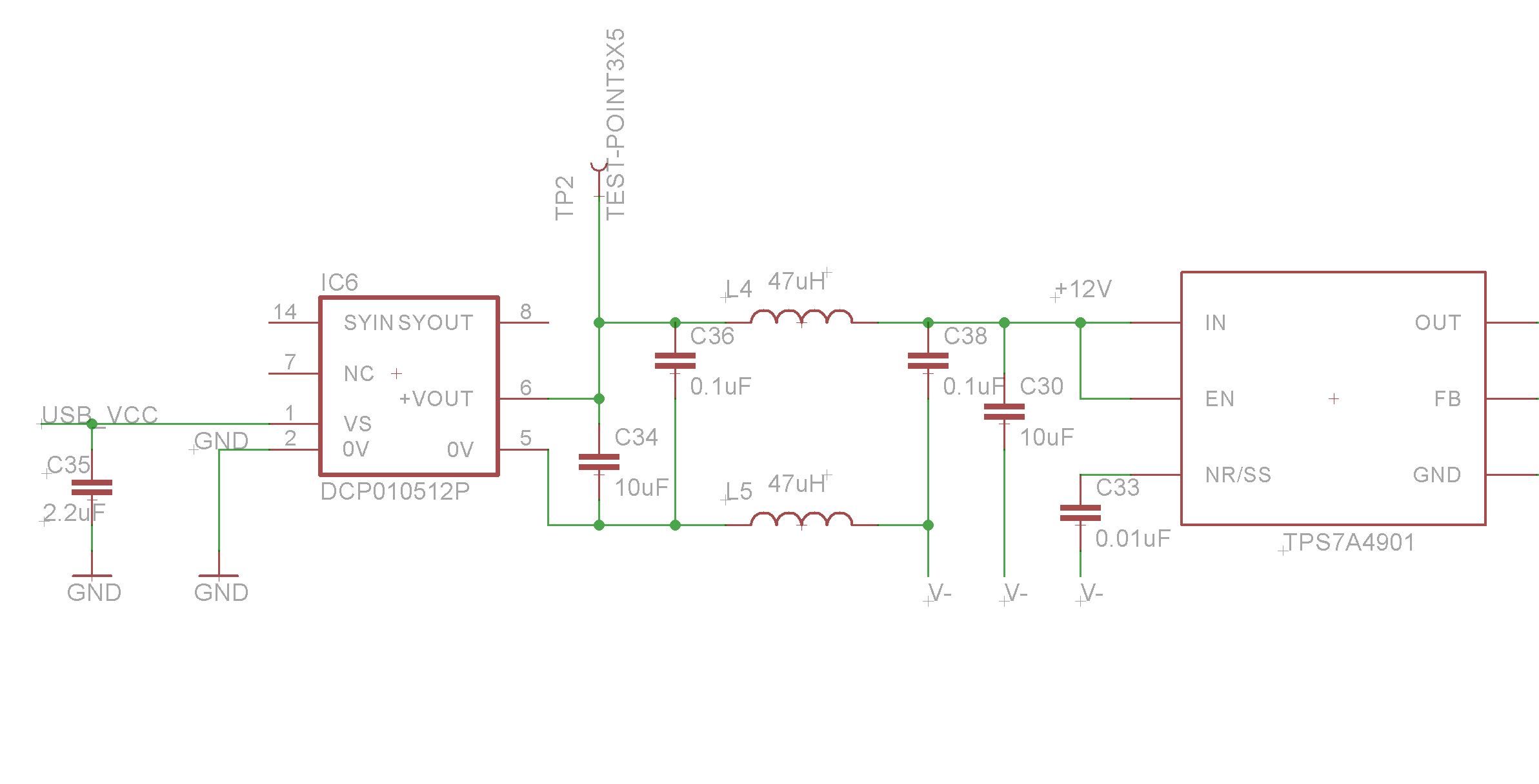
I am planning on using TI's DCP010512BP isolated DC-DC converter to enable use of USB power (5V -> 12V) but would like to design a filter of some sort to cut down on voltage rail noise as this is a switching regulator. Granted it will be regulated with an LDO down to 10V to give a nice +-5V rail before it makes its way to the OPA1622, but a CLC filter or something similar in between would be nice.
The switcher has a switching frequency of 800khz, thus leading me to want to design an LC filter with a resonance frequency of around 80khz to keep the resonant point well out of the expected noise. Maybe a 47uH inductor with 0.1uF caps? As far as the proper impedance of the filter, I have no idea... 50 ohms?
Here's what I've got right now:
Thanks
Do you have any experience with passive filter design?
I am planning on using TI's DCP010512BP isolated DC-DC converter to enable use of USB power (5V -> 12V) but would like to design a filter of some sort to cut down on voltage rail noise as this is a switching regulator. Granted it will be regulated with an LDO down to 10V to give a nice +-5V rail before it makes its way to the OPA1622, but a CLC filter or something similar in between would be nice.
The switcher has a switching frequency of 800khz, thus leading me to want to design an LC filter with a resonance frequency of around 80khz to keep the resonant point well out of the expected noise. Maybe a 47uH inductor with 0.1uF caps? As far as the proper impedance of the filter, I have no idea... 50 ohms?
Here's what I've got right now:
Thanks
Attachments
- Home
- Vendor's Bazaar
- New Audio Op Amp - OPA1622