this has been somewhat explored, Scott Wurcer, Walt Jung, Jerald Graeme all wrote about multiloop composite op amps - as well as Class A output (though mostly as discrete buffers)
Walt Jung "Op Amp Audio" series was mildy famous in headwise, other diy headphone amp forums for the "Jung Multiloop", "Diamond Buffer"
Walt's encyclopedic "Op Amp Applications" book is free online and has several sections showing composite op amps
Burr Brown/TI's Jerald Graeme has several books showing composite op amp techniques - some chapters were 1st published as company app notes
I couldn't figure out the TI website search or else it just doesn't find the old app notes by author - maybe johnc124 could look into that
google does a little better once you look in your files to see Burr Brown called them "application bulletins" https://www.google.com/#q=jerald+graeme+application+bulletin
Last edited:
maybe the voltage or impedance on enable pin could select between several bias settings similar to gain setting selection on tpa3116d2 allowing power saving or performance optimization in future design
Graeme had examples in his book "optimizing op amp performance" and some of those appear in this app note: http://www.ti.com/lit/an/sboa015/sboa015.pdf
10 PCS SOT23 MSOP10 SMD to DIP10 Adapter PCB Board Convertor Double Sides DT | eBay
Would this adapter make the OPA1622 DIY friendly?
As the soldering pads are quite long and extend beyond the chip, would the heat from a soldering iron on the pad transfer enough to properly solder each connection individually?
Would this adapter make the OPA1622 DIY friendly?
As the soldering pads are quite long and extend beyond the chip, would the heat from a soldering iron on the pad transfer enough to properly solder each connection individually?
10 PCS SOT23 MSOP10 SMD to DIP10 Adapter PCB Board Convertor Double Sides DT | eBay
Would this adapter make the OPA1622 DIY friendly?
As the soldering pads are quite long and extend beyond the chip, would the heat from a soldering iron on the pad transfer enough to properly solder each connection individually?
I don't see a pad to connect to the thermal pad on the bottom of the OPA1622. The thermal pad must be connected to V- for proper function of the op amp.
John
What standing current would you suggest for the OPA1622 to bias it into Class A? Would you recommend tying the CCS to the +ve rail or the -ve rail? Perhaps you could include class A biasing, optimising PSU decoupling, regulation etc. as an addendum to your excellent blog series to help users get the most out of the amp?
What standing current would you suggest for the OPA1622 to bias it into Class A? Would you recommend tying the CCS to the +ve rail or the -ve rail? Perhaps you could include class A biasing, optimising PSU decoupling, regulation etc. as an addendum to your excellent blog series to help users get the most out of the amp?
Last edited:
https://web.archive.org/web/20101203210751/http://www.analogzone.com/tmt_1002.pdf
I find the interesting part starting ~ p15 - the ever popular external Class A bias of an op amp output - but with actual measurements
Routputsum = 15 ohms and Vfwd = 0.6V (at 12V/20K of diode bias) gives (0.6/30) = 20mA of standing bias current. Experimenting with different values of standing bias current might be difficult, because you don't want to make Routputsum too large (excess Zout) or too small (opamps fighting). Thus you'll need to change Vfwd, either with Schottkies, Germanium diodes, diode connected transistors, precision bias networks, or a combination of these.
Great article by Xavier who still works on our High Speed Amplifier team here. I really miss EN-Genius as a publication space. We loved it. No word limits and almost immediate publication of content.
As for biasing the OPA1622 into class A:
1. Standing current is really going to be determined by the desired load current and acceptable power dissipation in the chip, which will greatly depend on the supply voltages.
2. I wouldn't expect which rail you connect the current source to to really matter. It was probably a bigger deal in older op amps with quasi-complementary output stages. But the output stage of the OPA1622 is so symmetrical I would predict essentially identical performance in either configuration.
I like the blog suggestion but they get a bit limited by the word count restrictions. Maybe an app note with a bunch of different OPA1622 circuits would be better.
John
The app note sounds good. If you do produce one, can I ask that, as well as applications for the OPA1622, you give specific advice on power rail regulation and local decoupling for optimum sound, including reg types, and the size and types of caps etc. The world and his wife have their own ideas on this but I'd like to hear from the team that designed and trialled the OPA1622.
Just looking again at the chip - 3 mm by 3 mm? Why so small and difficult for amateurs to use?
Last edited:
If a square hole was cut into this adapter, and a copper tab was soldered to the bottom of the OPA1622, and connected to the V-, would this make it DIY friendly?
10Pcs SO-10 / SOP-10 to DIP-10 IC Test Adapter Plate Converter Board | eBay
10Pcs SO-10 / SOP-10 to DIP-10 IC Test Adapter Plate Converter Board | eBay
John
The app note sounds good. If you do produce one, can I ask that, as well as applications for the OPA1622, you give specific advice on power rail regulation and local decoupling for optimum sound, including reg types, and the size and types of caps etc. The world and his wife have their own ideas on this but I'd like to hear from the team that designed and trialled the OPA1622.
Just looking again at the chip - 3 mm by 3 mm? Why so small and difficult for amateurs to use?
Will do. We prefer each OPA1622 have its own 1kVA torroid and a minimum of 10,000 uF per rail per 10mW of output power 😉
We didn't pick the package to purposefully make it difficult for amateurs. Rather we picked it so that companies that manufacture portable electronics could fit high quality components into very space constrained PCBs.
A number of hobbyists, some on this thread, are working on adapters for this part. I suspect there will be adapters sold on ebay by someone soon.
Bah humbug. My soldering skills are way past SON-10. Can I haz the wafer version please?
John
Please don't joke about that!! Someone will do it and say it sounds much better that way. I guarantee it.
Please don't joke about that!! Someone will do it and say it sounds much better that way. I guarantee it.
Bah humbug. My soldering skills are way past SON-10. Can I haz the wafer version please?
If you have wire bonding capability at home, could I get you to bond out a few thousand of these into 14-pin DIP packages for the folks here? 😀
John
Please don't joke about that!! Someone will do it and say it sounds much better that way. I guarantee it.
Datasheet results were obtained on a PCB with super-conducting ground and power planes cooled by liquid helium 😉 😉
If you have wire bonding capability at home, could I get you to bond out a few thousand of these into 14-pin DIP packages for the folks here? 😀
Ah but that will affect signal purity.... an additional metal to metal interface... noise and Seebeck effect... very bad...
It works best with the power supplies you mentioned and with gold wires bonded directly from the wafer to the supporting components. Hybrid ICs on ceramic substrate is the way to go with this one. The most crystalline yet fully bodied sound ever.

I think with regards to the OPA1622 you'd have to be careful what you do to it without turning it into something else. I suppose you could say give it more output current and possibly the ability to operate from higher power rails and you'd be making a lower power speaker amplifier 😀
For sure there are some difficult headphones to drive out there but they probably only represent 0.001% or something of the market.
This is a premium-ish opamp but that doesn't exclude it from somewhat affordable products. Lots of sound cards these days and some on board sound cards include headphone drivers. Some use the TPA6120, some use output buffers like the LME49600, but the point is they actually take the time and money to implement a headphone specific driver IC.
The OPA6122 is exciting for me because of its tiny form factor. The world is shrinking and I for one would be delighted to see it used in portable devices such as premium tablets. Some devices already have a push on good sound quality so this would fit in nicely.
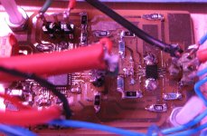
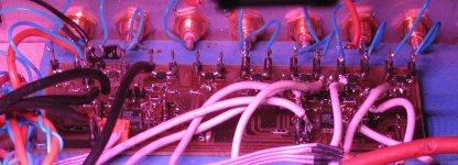
Attached are a couple of pics of my implementations.
One is the headphone board and the other is the 16 channel output board of which 12 channels are used. As it stands I didn't have the thermal pad connected to the reverse side of the PCB for power dissipation, but have 'wings' coming out of each side of the chip that enhances conduction away from the device. Of course the pad is connected to the -ve rail.
For sure there are some difficult headphones to drive out there but they probably only represent 0.001% or something of the market.
This is a premium-ish opamp but that doesn't exclude it from somewhat affordable products. Lots of sound cards these days and some on board sound cards include headphone drivers. Some use the TPA6120, some use output buffers like the LME49600, but the point is they actually take the time and money to implement a headphone specific driver IC.
The OPA6122 is exciting for me because of its tiny form factor. The world is shrinking and I for one would be delighted to see it used in portable devices such as premium tablets. Some devices already have a push on good sound quality so this would fit in nicely.
Attached are a couple of pics of my implementations.
One is the headphone board and the other is the 16 channel output board of which 12 channels are used. As it stands I didn't have the thermal pad connected to the reverse side of the PCB for power dissipation, but have 'wings' coming out of each side of the chip that enhances conduction away from the device. Of course the pad is connected to the -ve rail.
Attachments
- Home
- Vendor's Bazaar
- New Audio Op Amp - OPA1622