More and more posts in the forum deal with pseudo theories and unsupported claims about mysterious small signal distortions in circuits with negative feedback. I would like to post some of my measurements that prove that opposite is true in case of 'normal' design. I would like to encourage the others as well to post their results.
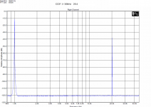
I am starting with a link-level preamplifier based on OPA627 and DRV134 and measurements related to 0dB = 146mV. I will appreciate your comments on 'small signal distortions'.
I am starting with a link-level preamplifier based on OPA627 and DRV134 and measurements related to 0dB = 146mV. I will appreciate your comments on 'small signal distortions'.
Attachments
Pavel, would it be possible to do some IMD measurements on that component, where the level of the 2nd signal is down -20, -40, -60, etc, compared to the 1st - to satisfy my curiosity ...
Thanks,
Thanks,
https://web.archive.org/web/20101203210751/http://www.analogzone.com/tmt_1002.pdf
I find the intersting part starting ~ p15 - the ever popular external Class A bias of an op amp output - but with actual measurements
I find the intersting part starting ~ p15 - the ever popular external Class A bias of an op amp output - but with actual measurements
Pavel, would it be possible to do some IMD measurements on that component, where the level of the 2nd signal is down -20, -40, -60, etc, compared to the 1st - to satisfy my curiosity ...
Thanks,
Frank, I appreciate your curiosity. Reducing amplitude of the 2nd signal only makes things easier for the amplifier.
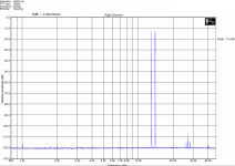
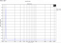
1) 19+20kHz. All intermodualation products disappear and the only product you can see is the 2nd harmonic of 19kHz, i.e. 38kHz, about 96dB below 19kHz line level. Further reducing of 2nd signal amplitude brings no change so please allow me not to post images.
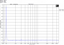
2) 1+20kHz. No intermodulation products available.
The conclusion is that smaller the signal components less work for the amplifier, in this circuit under test.
Attachments
https://web.archive.org/web/20101203210751/http://www.analogzone.com/tmt_1002.pdf
I find the intersting part starting ~ p15 - the ever popular external Class A bias of an op amp output - but with actual measurements
Thanks for the link, this is a good and interesting publication.
We may also replace rail resistor by self-biased JFET.
My question - in case of 1mA output stage idle current and 10k load the output pp stage would remain in class A up to 20Vp output voltage (never used in a link stage). Does it make any sense to use output stage supply resistor then? I understand it may make sense for 600 ohm load, but then I would go for a BUF634 or discrete buffer.
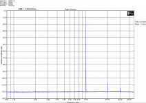
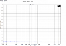
Also interesting is no big influence of heavy load in case of small signals. Output impedance is 50 ohm, please compare effect of 10k and 50 ohm load. We can see the plot shifted down by 6 dB (50R : 50R divider). 0dB = 150mVrms approx., as shown in 1st post of the thread.
Attachments

would like to post some of my measurements that prove that opposite is true in case of 'normal' design.
Test using sine waves?
dave
I would prefer real music. The tests with easy to reproduce periodic signals can really only prove something about periodic signals.
dave
dave
I would prefer real music. The tests with easy to reproduce periodic signals can really only prove something about periodic signals.
dave
Good, you can participate in my ABX tests.
http://www.diyaudio.com/forums/everything-else/246687-ultimate-listening-test-trial-no-3-a.html
Good, you can participate in my ABX tests.
I'd like too, even downloaded some of the files.
I do have my reservations over ABX. And i'd need native software for OSX.
dave
+1 (to planet10 that is 😀) - music is multitone stimulus, high crest factor.
Multitone is one of the easiest.
Attachments
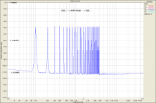
Yes - but 30 tones (I didn't count, just eyeballed) isn't really music-like enough, unless the music is staple 'audiophile' fare. Why not 300+?
You know guys I like the recommendations. But I do not like unsupported claims and pseudo-theories that are often offered by 'gurus' that in fact try to support their design philosophy and commercial success at first place. I am in both camps, objective and subjective. IMO, good parameters are necessary to get good sound, i.e. I cannot tolerate 'mask and hide' approach. And that's what you really often get, no names. If you read in other threads, you will see that my key target is the fight with EMI interference and its influence to audio signal. This is the second must, together with perfect audio band parameters.
And aperiodic.
dave
Makes no difference in a well designed circuit.
Makes no difference in a well designed circuit.
Is there any proof of that?
dave
Is there any proof of that?
dave
Yes, nothing significant measured. Look, these measurements are time consuming. So it makes much sense to save results that show problems rather than those that are perfect.
- Status
- Not open for further replies.
- Home
- General Interest
- Everything Else
- Small signal myths and real measurements