0V ?
I think there's some varnish in the vias that isolates it.
See if you can measure ground there.
I think there's some varnish in the vias that isolates it.
See if you can measure ground there.
0V ?
I think there's some varnish in the vias that isolates it.
See if you can measure ground there.
yeah, I already found it, added 2000u polymer
Sara K. from Chesky Records sounds even better... after an hour or so I touched the cap, it was warm.
Dear Soeren, could you give any estimates about a new boards batch availability? Personally I would happily buy previous generation if it is still available while the new generation is far away.
dam 1021 rev7
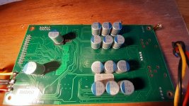
So, the dam1021 rev7 is about to ship.... I have put a picture of the rev7 up on my website, and as people as usually are going to ask question, let me try to answers them up from:
1) it use the same FPGA and same uC as usual, so should be able to use same firmware, there are some differences, so new firmware are needed and will autodetect board.
2) The shift registers are now also in the smaller qfn packaging as used on other boards, so I don't need to stock the tssop types anymore....
3) Output shift registers now running at 1.4M/1.5M sample rate, making FIR2 filter different. Will require new filter file, but plan to use same filter file for both old and new boards, firmware will load filters as needed.
4) The R-2R network is now 24+3+1, ie 24 bit classic R-2R network, 3 bit thermometer network, plus the sign, total 28 bits.
5) Yes, still same Si514 clock, but now in a small package (like I use on other boards), and it drives the shift registers directly, no added jitter by going though the FPGA. People who want to bitch about the Si514, please go elsewhere, we have heard you multiple times....
6) The clock Power supply is separate and use a LP2907 low noise regulator.
7) New vref supplies, like used on the dac2541. For those who want details, yes it use a opamp with transistor buffer, with a polymer output capacitor. Lower vref impedance from DC to Megahertz.
8) Those are powered at +-5.4V from LM317/LM337 pre regulators.
9) Output opamps are opa1678.
10) Power in are now DC only, optimal is +- 9V.
11) The board is mechanical and almost electrical compatible with previous version of the dam1021.
12) J9 is 4 bits user i/o, planning to use it for additional SPDIF inputs.
13) The non isolated serial management port is now TTL levels, not real RS232 levels. So get the right USB to serial adapter....
I know people want to experiment anyway, but there is nothing to gain by vref or power supply modifications....
To simplyfying stock keeping I will probably only make dam1021-12.
Last edited:
5) Yes, still same Si514 clock, but now in a small package (like I use on other boards), and it drives the shift registers directly, no added jitter by going though the FPGA. People who want to bitch about the Si514, please go elsewhere, we have heard you multiple times....
I didn't think you have the exclusive property of this thread, I thought it was a public thread.
And it's really curious that you get your hands ahead about the Si514, the Si570 was too expensive?
Looks great. So J10 is gone?
I will try this one, but probably not replace the 16 DAM1021 boards in my multichannel converter...
Soeren, could you please also give us an estimate regarding the overhaul of the clocking software? Thanks!
I will try this one, but probably not replace the 16 DAM1021 boards in my multichannel converter...
Soeren, could you please also give us an estimate regarding the overhaul of the clocking software? Thanks!
I didn't think you have the exclusive property of this thread, I thought it was a public thread.
Holy sh*t andrea, it's literally the guy behind all soekris products. You're going to run it in his place, maybe? Move on, plenty of other threads to continue your usual discussions.
@soekris, thanks for the info about rev7.

Holy sh*t andrea, it's literally the guy behind all soekris products. You're going to run it in his place, maybe? Move on, plenty of other threads to continue your usual discussions.
@soekris, thanks for the info about rev7.
This thread is public and even I'm a customer so ...
... so I believe I don't need your permission to post my comments.
yup, thank you for your help Danny. Not sure if NOS filter will bring some improvements? As I said earlier, I'm not worried about HF noise 🙂Now after the mods, you have a very good DAC 🙂
😱
So what was it before the mods?
It was a pretty cool dac 😉
Got the 1000uf 16V polymer caps today and implimented one decoupling the 3.3V regulator input. Obvious improvement, sounds more real, detailed and clearer bass punch. Cheap and easy ugprade. This and a 1500uf 6.3V regulator output decoupling cap are mandatory IMO.
Not sure if NOS filter will bring some improvements?
I didnt like NOS filter with dam1121, but I have preferred NOS (or at least not disliked it) with other true NOS DACs.
It may be that some or most of the NOS charm comes from the lower clock frequencies (and potentially lower jitter), which the soekris NOS filter will not have since the input is still oversampled to the same rate only with duplicated samples.
'NOS filter' is a bit of an oxymoron.
Got the 1000uf 16V polymer caps today and implimented one decoupling the 3.3V regulator input. Obvious improvement, sounds more real, detailed and clearer bass punch. Cheap and easy ugprade. This and a 1500uf 6.3V regulator output decoupling cap are mandatory IMO.
I looked at the data sheet of the 17L33 regulator, I suppose it is the NCP1117 from ON. You see page 6 fig. 12 that there is indeed a risk for instability with the way it was used in the DAM. Data sheet advices 10uF at input and output and care for the minimum impedance... increasing the Cout above 100uF should deal with that issue once and for all. Personally I would also increas the Cin at approximately the same value. I don't understand Rev7 does not include some more capacitance around that regulator (there was space to do it), but the oscillation issue seems to be dealt with by increasing the trace-length between Vout and Cout by a little loop 🙂 I have myself 680uF and 1000uF directly on the regulator and it is indeed solving all issues and decreasing noiselevel on the 3.3v powerplane. In the end I have 3 x 680uF on the 3.3V powerplane with very good results.
Last edited:
But rev7 uses AZ1117E, marked GH27G.I don't understand Rev7 does not include some more capacitance around that regulator
Another interesting change I see on rev7 is the increase in pre-regulator voltage for Vref. It was 5V and now increased to 5.4V... important changes to get 'only' 0.4V more. Does the DAM2541 use the same Vref opamp? Anybody an idea why that additional .4V would be necessary or does it just give the opamp some more headroom & performance?
I looked at the data sheet of the 17L33 regulator, I suppose it is the NCP1117 from ON. You see page 6 fig. 12 that there is indeed a risk for instability with the way it was used in the DAM. Data sheet advices 10uF at input and output and care for the minimum impedance... increasing the Cout above 100uF should deal with that issue once and for all. Personally I would also increas the Cin at approximately the same value. I don't understand Rev7 does not include some more capacitance around that regulator (there was space to do it), but the oscillation issue seems to be dealt with by increasing the trace-length between Vout and Cout by a little loop 🙂 I have myself 680uF and 1000uF directly on the regulator and it is indeed solving all issues and decreasing noiselevel on the 3.3v powerplane. In the end I have 3 x 680uF on the 3.3V powerplane with very good results.
Low end sounds quite different with the VIn cap added (Vout cap had been added long before). There was always a little bit bass missing with the DAM1021, but this rectified it.
Where did you place the other 3 680uf caps?
Last edited:
It may be that some or most of the NOS charm comes from the lower clock frequencies (and potentially lower jitter), [...]
Thought so, too.
Low end sounds quite different with the VIn cap added (Vout cap had been added long before). There was always a little bit bass missing with the DAM1021, but this rectified it.
Where did you place the other 3 680uf caps?
I implemented both, Cin&out at the same time, but I mixed-up the high and low voltage caps between Vin en Vout.. so I have the 6.3V polymer on Vin at 8.5V for now.. 🙄 not a long term solution..
I inserted the other two caps on the bottom of the board, as close to the board as possible (with an smd-cap plastic spacer to avoid shorts) on J9 and J2. I'm rather confident, these connect directly to the right powerplanes for 3.3V without too much trace in between.
Attachments
But rev7 uses AZ1117E, marked GH27G.
Didn't saw that, good point.
- Home
- Vendor's Bazaar
- Reference DAC Module - Discrete R-2R Sign Magnitude 24 bit 384 KHz