D
Deleted member 148505
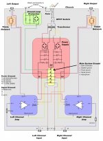
- You can use the grounding scheme attached (not mine, credits to the rightful owner)Hi lester, how are you ?
I try to find a buffer suitable to improve the JLE/JLA... whichever source I plug-in I have noise ... and without source no noise...
I want to test a simple circuit....:
...before order somme discrete input buffer:
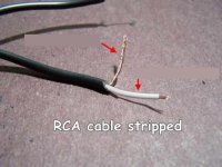
- Use shielded wire for all input signal wire connections (you can use spliced RCA cable if you don't have access to shielded wire)
- Do not put a volume control on the JLE/JLA module's input. It requires low impedance input drive.
- Put the Volume control on the input of the buffer or preamp. (I do see some preamp designs which put the potentiometer at their very output with no follower which is not good for JLE/JLA modules, buffer is still needed if that is the case)
- You might have lots of gain on your system. You can lower the gain of JLE/JLA module by changing input resistor value.
It depends on your taste.Witch one are better ?
Need input cap on JLA for the JFET cascode and OP-AMP 5534 board ?
The Diamond are already an output cap...
You should put the potentiometer / volume control on the buffer's input.
Yes it needs input cap if the buffer's output doesn't have it, use nichicon muse 22uf electrolytic.
Regards,
Lester
Attachments

I make some test this week-end with a DIY NE5532 buffer (a simple voltage follower), no difference...
With no source = no noise
With the buffer (or other source connected) = noise
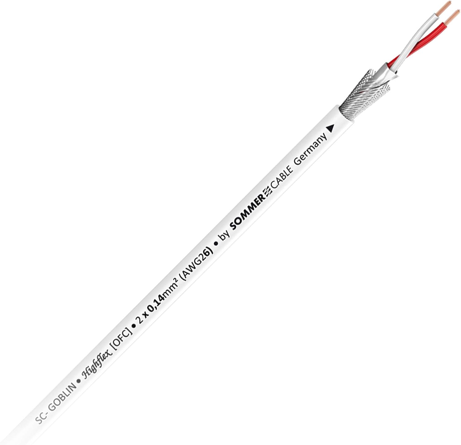
I use shielded wire (Sommercable Onyx) already...
I know this schema Lester... i already do this... and other configuration... no change.
I haven't ground loop protection... you know where I can find a good ground loop protection board ?
You think a screened cable is better for my problem ?
With no source = no noise
With the buffer (or other source connected) = noise
I use shielded wire (Sommercable Onyx) already...
An externally hosted image should be here but it was not working when we last tested it.
I know this schema Lester... i already do this... and other configuration... no change.
I haven't ground loop protection... you know where I can find a good ground loop protection board ?
You think a screened cable is better for my problem ?
Last edited:
D
Deleted member 148505
I make some test this week-end with a DIY NE5532 buffer (a simple voltage follower), no difference...
With no source = no noise
With the buffer (or other source connected) = noise
I use shielded wire (Sommercable Onyx) already...
I know this schema Lester... i already do this... and other configuration... no change.
I haven't ground loop protection... you know where I can find a good ground loop protection board ?
Hi Alex, try these changes in order:
1. Change all low level signal wires to shielded cables / RCA cables.
2. Connect GND wire of JLE/JLA module to Speaker GND terminal.
3. Connect Speaker GND terminal to Main power supply GND
4. Use ground lift 10 ohms from source GND to JLE/JLA input GND.
5. Try to use different supply for speaker protection.
Do you have picture so that we can re-route the wires?
Regards,
Lester
Hi Alex, try these changes first:
1. Change all low level signal wires to shielded cables / RCA cables.
2. Connect GND wire of JLE/JLA module to Speaker GND terminal.
3. Connect Speaker GND terminal to Main power supply GND
Do you have picture so that we can re-route the wires?
Regards,
Lester
This weekend i test screened cables and ground loop protection... i already test the 1nF cap on between chassis and input GND, no change...
I specify that the problem is similar with LJM L15D-SMD and JLA / JLE ...
Sorry no picture... I can do that this weekend...
D
Deleted member 148505
I also tried LJM L25D, shielded cable is a must otherwise there will be a hiss.
Also important that the GND of the module is referenced to speaker ground, then connect speaker ground to power supply ground.
Stripped RCA cable will suffice.
(photo not mine, credits to the owner)
Also important that the GND of the module is referenced to speaker ground, then connect speaker ground to power supply ground.
Stripped RCA cable will suffice.
(photo not mine, credits to the owner)
Attachments
I also tried LJM L25D, shielded cable is a must otherwise there will be a hiss.
Also important that the GND of the module is referenced to speaker ground, then connect speaker ground to power supply ground.
Stripped RCA cable will suffice.
(photo not mine, credits to the owner)
Yes, speaker GND, module GND, input source GND and supply GND are connected together ...
It's possible that the SMPS do that ?
With connex SMPS300R on 5x JLA-250D = noise
With ebay no name SMPS500W on JLE-800S / L15D-SMD = noise
With connex SMPS2000R on Sure IRS2092 (with PGA4311) = no noise
I already use RCA stripped cable (SC-Onyx 2025):
On my main system (Sure IRS2092)= no noise and on 5 channels JLA = noise
D
Deleted member 148505
Yes, speaker GND, module GND, input source GND and supply GND are connected together ...
It's possible that the SMPS do that ?
With connex SMPS300R on 5x JLA-250D = noise
With ebay no name SMPS500W on JLE-800S / L15D-SMD = noise
With connex SMPS2000R on Sure IRS2092 (with PGA4311) = no noise
I already use RCA stripped cable (SC-Onyx 2025):
On my main system (Sure IRS2092)= no noise and on 5 channels JLA = noise
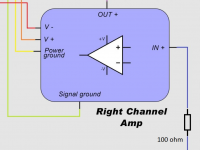
You can fix it with correct wiring, use T-ground instead of star ground, use a strip of copper or PCB copper for connecting the grounds and with correct order (on attached pic) then on the input of JLA module, use a 100 ohm resistor (blue wire on attached pic)
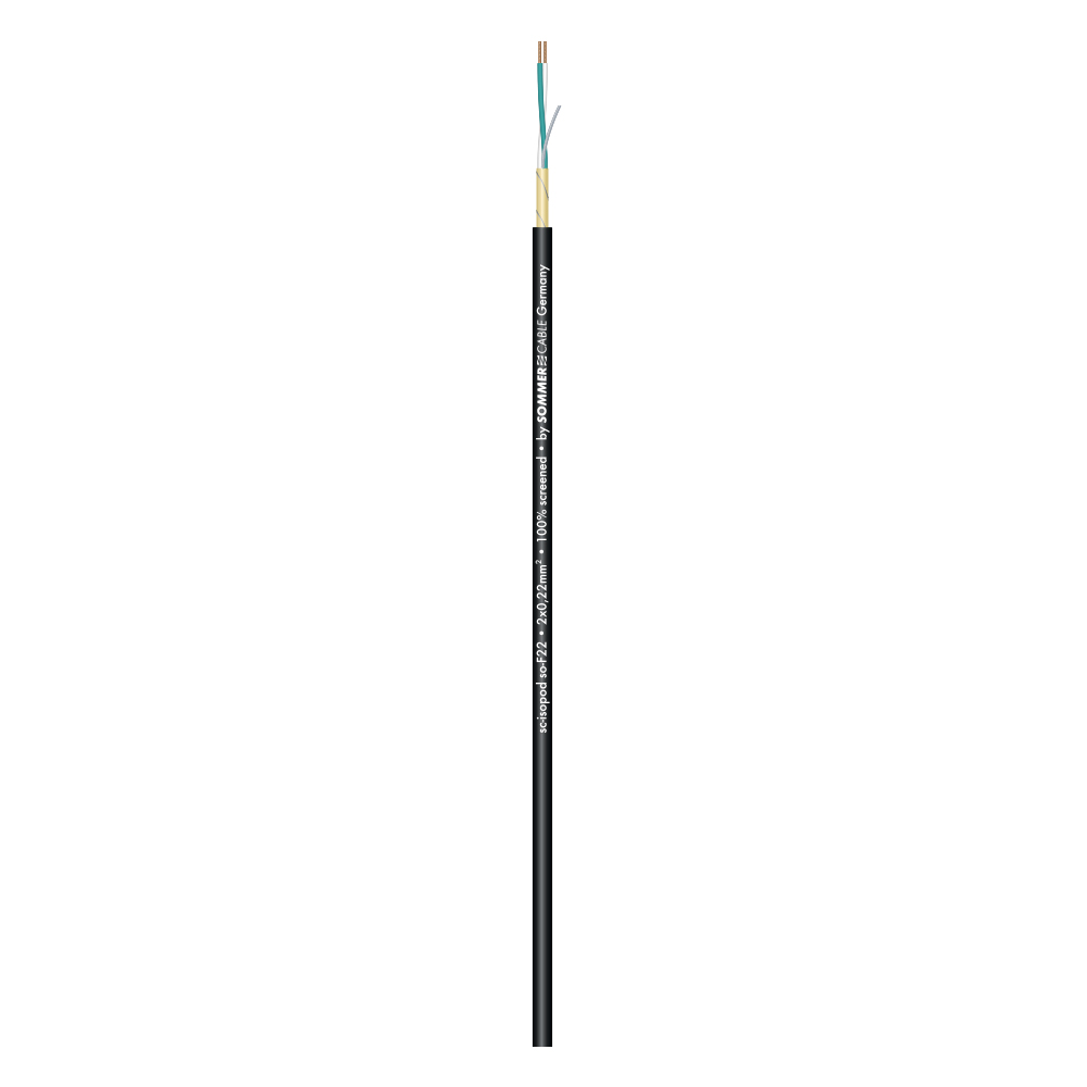
I have ordered some Sommercable Isopod SC-F22 100% screened and wire:
White on GND input
Green on + signal input
Screen on GND input...
Try to disconnect white cable since it is for the - balanced signal.
Attachments
Try to disconnect white cable since it is for the - balanced signal.
No, that's the principle of total screened earth wiring to connect the - signal cable and the shield on the GND input:
An externally hosted image should be here but it was not working when we last tested it.
The total earth wiring prevents current from flowing through the shielding braid. Thus, the electromagnetic disturbances blocked by the braid can in no case disturb the signal when these weak currents are discharged to ground.
Last edited:
You can fix it with correct wiring, use T-ground instead of star ground, use a strip of copper or PCB copper for connecting the grounds and with correct order (on attached pic) then on the input of JLA module, use a 100 ohm resistor (blue wire on attached pic)
What is the difference between T ground and Star ground ?
Ok for the resistor but in serial with input signal or in parallel between + and GND input ?
Last edited:
D
Deleted member 148505
No, that's the principle of screened wiring to connect the - signal cable and the shield on the GND input:
An externally hosted image should be here but it was not working when we last tested it.
Usually on unbalanced connections, single core wire is being used as the hot and the screen is being used as the return path / gnd signal.
For 2 core + screen cable, usually it is being used for balanced connections. Green and white core is for hot and cold while the shield is for ground.
What is the difference between T ground and Star ground ?
Ok for the resistor but in serial with input signal or in parralel between + and GND input ?
use it in serial to + input. (see attached pic)
Regards,
Lester
Attachments
Usually on unbalanced connections, single core wire is being used as the hot and the screen is being used as the return path / gnd signal.
For 2 core + screen cable, usually it is being used for balanced connections. Green and white core is for hot and cold while the shield is for ground.
Your right, "usually" this is that... but this in a special case named "total ground cable"...
Ok for the resistance i have some in stock...
D
Deleted member 148505
Upcoming updates on previous modules.
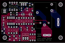
Line Level Signal Detection THT V1
Same functionality as before and same PCB size but through hole parts were used for easier assembly.
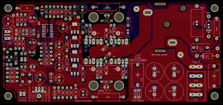
IRCore2000 V1.2
Changed gate buffer to more powerful zetex transistors FZT853 and FZT953
Line Level Signal Detection THT V1
Same functionality as before and same PCB size but through hole parts were used for easier assembly.
IRCore2000 V1.2
Changed gate buffer to more powerful zetex transistors FZT853 and FZT953
Attachments
D
Deleted member 148505
Upcoming amplifier modules next month.
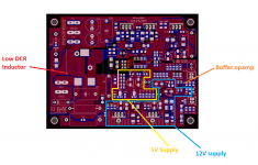
IRCore350M - Audiophile Grade IRS2092 Amp
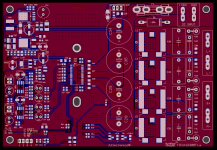
TICore260BTL - TPA3255 Fixed Stereo BTL Amp
They will be available on my eBay page soon.")
IRCore350M - Audiophile Grade IRS2092 Amp
- All housekeeping supplies are linear regulators.
- LDO regulators with 2 stage noise filter were used on 5V analog supplies of IRS2092.
- Compatible with low DCR (2.5 mOhm) inductors from coilcraft or bourns.
- Infineon optimos for output mosfets.
- Onboard buffer is included with selectable inverting/non-inverting jumper (for bridging 2 modules)
- Open collector mute input.
TICore260BTL - TPA3255 Fixed Stereo BTL Amp
- XL7015 / LM2576HV 150kHz switching regulator for 15V Supply
- Properly implemented LM317 for 12V supply
- Voltage supervisor for reset control and zero turn-on/off pops or clicks.
- Single ended input NE5532 buffer and nichicon muse input capacitors.
- SCR + TVS + Fuse for overvoltage / transient protection
- Overkill zobel network
- 18mm diameter tank capacitors.
They will be available on my eBay page soon.
Attachments
Great news Lester !
You finally made a TPA3255... once you tell me that too complicated and "costly"...
Proposition, can you out a better 12V regulator thant LM317 ? (TPS7A4700 and LT3045 is far better...)
Same the 5532 it's a "classical one" but OPA2140, OPA1656, OPA2134, LME49860, LT1364 (etc etc) is better for a resonable price...
D
Deleted member 148505
To reduce complexity, we only set the mode to stereo BTL configuration. Then SE input, and master mode, so no complicated jumpers for the user.Great news Lester !
You finally made a TPA3255... once you tell me that too complicated and "costly"...
Proposition, can you out a better 12V regulator thant LM317 ? (TPS7A4700 and LT3045 is far better...)
Same the 5532 it's a "classical one" but OPA2140, OPA1656, OPA2134, LME49860, LT1364 (etc etc) is better for a resonable price...
For the opamp buffer, default IC soldered is NE5532, but the PCB trace is compatible with DMP8 and SOIC-8 package so you can upgrade it to OPA1656 and other dual opamp ICs.. you just need hot air soldering tool to replace it.
In the future maybe we will release a version with premium 12V regulator. For now the choice is LM317 to reduce the price to 68USD + 24USD shipping.
The IRcore350M is the new version of JLE-800s your promised for 2020 ?
Yes, IRCore350M is our latest IRS2092 amp, max voltage is +/-60V. Aside from other improvements mentioned, we've placed a switching noise filter on feedback for better THD performance. It will be priced to 46USD + 15USD Shipping.
To reduce complexity, we only set the mode to stereo BTL configuration. Then SE input, and master mode, so no complicated jumpers for the user.
For the opamp buffer, default IC soldered is NE5532, but the PCB trace is compatible with DMP8 and SOIC-8 package so you can upgrade it to OPA1656 and other dual opamp ICs.. you just need hot air soldering tool to replace it.
In the future maybe we will release a version with premium 12V regulator. For now the choice is LM317 to reduce the price to 68USD + 24USD shipping.
Yes, IRCore350M is our latest IRS2092 amp, max voltage is +/-60V. Aside from other improvements mentioned, we've placed a switching noise filter on feedback for better THD performance. It will be priced to 46USD + 15USD Shipping.
OK great ... i made the mod myself for the LM317 (LT3045 exist in LM317 form factor for replacement) and for OPA don't worry...
When it's available ?
Can you post the measurement of the two when it's finished ?
For the TPA3255 wich inductor can you put ?... i don't recognize the PCB trace... the TPA is very infuenced by the output inductor (like IRS2092 and all classD), see the measurement of 360customs:
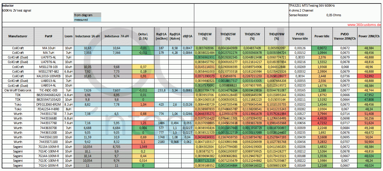
Best one is wurth 7443630 7µH but he don't test the Coilcraft AGP2900 or SER2900...
Last edited:
D
Deleted member 148505
OK great ... i made the mod myself for the LM317 (LT3045 exist in LM317 form factor for replacement) and for OPA don't worry...
When it's available ?
Can you post the measurement of the two when it's finished ?
For the TPA3255 wich inductor can you put ?... i don't recognize the PCB trace... the TPA is very infuenced by the output inductor (like IRS2092 and all classD), see the measurement of 360customs:
link
Best one is wurth 7443630 7µH but he don't test the Coilcraft AGP2900 or SER2900...
It will be available within a month from now. Will post some measurements soon.
Here are the compatible inductors for the PCB trace.
SRP1770C-100M
SRP1770TA-100M
SER1512-103MED
CDEP15D90T150NP-100MC-125
CDEP15D90T150NP-100MC-100
B82559A7103A016
The list will be updated if we find some more.
Inductors should have a linear or soft saturation curve, so there will be minimal change in inductance on high current bursts. Then it should have a low dc resistance, less than 14mOhm is good.
Another criteria is the cost so the default soldered inductor will be the most cost effective one.
Yes I know that Lester, the trace is too thin for SER2900... SER1512 as good choice but Isat is lower...
- Status
- Not open for further replies.
- Home
- Vendor's Bazaar
- Amplifier Modules and PCBs For Sale