Hi lester.
Good you reminded me of the solder links,
Yes I noticed when matching the transistors that warmth from handling the transistors altered the hfe, now they are evend out.
No the mosfet is indeed an irfp240, but it's the original Samsung from the happy 90s, salvaged from an pa amp, I do enjoy recycling.
I totally forgot the 10 ohm resistor in the coil.
Hope all is well where you are, heard about that volcano going unstable.
Is there a reason other than practical to put the resistor inside the coil? Does it induce some current to resistor??
I find it difficult to fit the resistors, but there's plenty of space underneath pcb.
I find it difficult to fit the resistors, but there's plenty of space underneath pcb.
No,do not place the resistor inside the coil,isn't a good practice!Is there a reason other than practical to put the resistor inside the coil? Does it induce some current to resistor??
I find it difficult to fit the resistors, but there's plenty of space underneath pcb.
Place it across the coil or under the coil in the soldering side.
Hi thimios.
Thanks for reply.
I actually just put the resistors underneath, the spacers are 8mm so room enough.
Good practice? I'm curious why..?
Thanks for reply.
I actually just put the resistors underneath, the spacers are 8mm so room enough.
Good practice? I'm curious why..?
D
Deleted member 148505
I see no significant problem from it if you will use a non-inductive resistor inside the coil. (kindly point me to a study or an experiment if I am wrong).
It saves some PCB space and it looks good, haha.
Though placing the resistor under the PCB is better.
Thanks for the concern about the taal volcano, hope it won't erupt violently soon.
It saves some PCB space and it looks good, haha.
Though placing the resistor under the PCB is better.
Thanks for the concern about the taal volcano, hope it won't erupt violently soon.
I've been fiddling with the four ska150 boards, 3 of them work excellent, the last is a mystery, I can adjust bias up until 20Ma, beyond that bias goes haywire jumping from 1 to 1.5 amps, I checked that all parts are correct, functioning, and rotated correctly, the I checked every single solder, as far as I can tell, they are all good.
I am able to adjust the dc to almost perfect zero,
It must be the bd139/140 with the current sources that are bad, I just can't figure it out, any good advice?
Regards.
Thomas.
Ps no oscillations.
I am able to adjust the dc to almost perfect zero,
It must be the bd139/140 with the current sources that are bad, I just can't figure it out, any good advice?
Regards.
Thomas.
Ps no oscillations.
Last edited:
D
Deleted member 148505
I've been fiddling with the four ska150 boards, 3 of them work excellent, the last is a mystery, I can adjust bias up until 20Ma, beyond that bias goes haywire jumping from 1 to 1.5 amps, I checked that all parts are correct, functioning, and rotated correctly, the I checked every single solder, as far as I can tell, they are all good.
I am able to adjust the dc to almost perfect zero,
It must be the bd139/140 with the current sources that are bad, I just can't figure it out, any good advice?
Regards.
Thomas.
Ps no oscillations.
Can you share a picture on how the wiring was done while you measure the bias, is it connected to source and speakers? Did you use ground lift and have you replaced any part's values?, some parts might be out of spec.
Also please resolder the solderlink part under the board.
Tighten the fuse on the holder. Might be some loose connections, like power supply, etc..
Regards,
Lester
Okay.
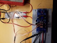
Here's what I've been doing.
The boards are not complete I'm awaiting capacitors this week, the components missing are c8 on zobel. c6-c7.c1 bipolar .c3 6pf ( now its running with a 10pf). C9 ( now running with 50v 100uf) .
The only parts that are not within spec are the r15 to r18, they are supposed to be 3k mine are 2k8.
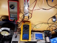
I'm testing it from two series connected lab supply at +/÷ 25 volt.
I'm measuring bias through the two fuses, the fuses are blown and each is wired to a 250 ohm dummy resistor, the two Dmm are measuring the voltage drop on each resistor.
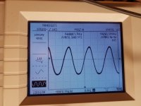
Today I hooked up the scope and did read oscillations 1.2 mhz.
If I try increase bias so the dmm read 1 volt drop it suddenly becomes unstable and the full rail voltage comes across resistors.
If this because missing parts? Or am I doing something wrong? I suppose the modules are able to run of 25 volt
Here's what I've been doing.
The boards are not complete I'm awaiting capacitors this week, the components missing are c8 on zobel. c6-c7.c1 bipolar .c3 6pf ( now its running with a 10pf). C9 ( now running with 50v 100uf) .
The only parts that are not within spec are the r15 to r18, they are supposed to be 3k mine are 2k8.
I'm testing it from two series connected lab supply at +/÷ 25 volt.
I'm measuring bias through the two fuses, the fuses are blown and each is wired to a 250 ohm dummy resistor, the two Dmm are measuring the voltage drop on each resistor.
Today I hooked up the scope and did read oscillations 1.2 mhz.
If I try increase bias so the dmm read 1 volt drop it suddenly becomes unstable and the full rail voltage comes across resistors.
If this because missing parts? Or am I doing something wrong? I suppose the modules are able to run of 25 volt
Attachments
D
Deleted member 148505
I see, let's wait for the tank capacitors and zobel. Then check again.
Tank caps placed near the mosfets help a lot since you are using long wires to connect the module to the power supply.
Also instead of long wires, just solder a 10 ohm 3w resistor on each blown fuse, make sure the connection of each fuse to the fuse holder is tight.
Then adjust bias without input and speakers attached.
You're right, there are to many unknowns with the missing parts, but you probably know the felling with exiting new build, it can't go to fast.
I'll return when missing parts are installed.
Thanks..!
Thomas
I'll return when missing parts are installed.
Thanks..!
Thomas
Back..
I got the rest of the parts and assembled one board, all is good, no oscillations at all, dc offset is ridiculously close to zero, it's now running at 53 volts and biased at 200Ma pr rail, is there an ideal bias current? One module is in middle using 30 watt from wall outlet.
I'm happy with result I'm sure they will sing beautifully..
D
Deleted member 148505
Back..
I got the rest of the parts and assembled one board, all is good, no oscillations at all, dc offset is ridiculously close to zero, it's now running at 53 volts and biased at 200Ma pr rail, is there an ideal bias current? One module is in middle using 30 watt from wall outlet.
I'm happy with result I'm sure they will sing beautifully..
I've read that Greg recommends 125mA bias, if you have a good heatsink you can increase it but according to him he didn't recognize any audible benefit on increasing the bias.
Put the bias trimmer fully clockwise for lowest bias. (same with greg ball's pcb)
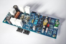
Attached my build, I used nichicon caps all throughout, fine gold on bootstrap cap and muse on input cap. Will gonna replace the zobel cap soon with wima 10mm pitch 100nf.
Attachments
Nice clean build you have there, okay so I finished all 4 modules today, but the last is giving me some headache, it uses the exact same parts as the others, but when powering up and setting bias it gets self exited when bias reaches 100mv, its resonates at 6 mhz, I checked all parts, orientation and resoldered all points, afterwards checked with magnifying glass, all seems good, I tried to put a 15pf across c3 to slow it down, but it actually made things worse, I shorted input and got same result, solderlink 2 is linked and good, i tried both options on solderlink 1 at input , no difference, also tried all of the above with 8 ohm dummy load attached, so any suggestions are more than welcome.
Back again. .
.
Well after my last frustrated post, I took some coffee and decided to clean the mess on my work table and give it another go
So I cleaned table of parts cables wire cuts etc, hooked it all up again, I took oscilloscope probe and wanted to reconnect it when I noticed I had the cable around the vario transformer😀😕
The probe cable had picked up emf and fed it to amp feedback🙄
All is good..
.Well after my last frustrated post, I took some coffee and decided to clean the mess on my work table and give it another go
So I cleaned table of parts cables wire cuts etc, hooked it all up again, I took oscilloscope probe and wanted to reconnect it when I noticed I had the cable around the vario transformer😀😕
The probe cable had picked up emf and fed it to amp feedback🙄
All is good..
D
Deleted member 148505
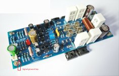
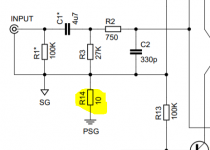
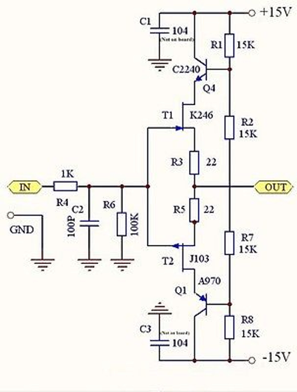
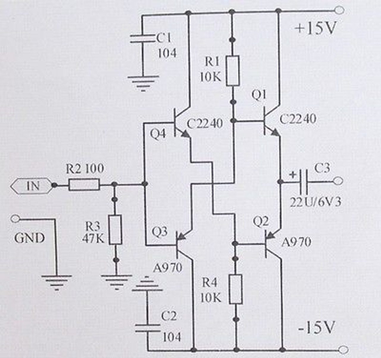
On my latest PCB (V2) I removed the ground lift resistor (see attached pic of original gb150d schem) , so if you put it back maybe it would help with emf sensitivity.
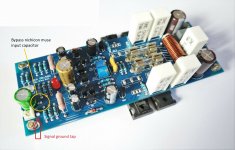
Try to remove solderlink connection (by using solder wick) and then I have placed a signal ground tap on the pcb (arrow on attached picture) connect it to speaker ground via 10 ohms. (or 4.7 ohms, then 1 ohm whichever suits your build)
There's also a similar thread on this site:
Problems adjusting bias current on SKA GB150D
Regards,
Lester
Attachments
D
Deleted member 148505
Hi Lester. Interested in the IRCore2000 PCBs you're selling on Ebay. Do you have a rough estimate for cost of US sourced parts (Mouser, Digikey, etc.) per board? I have a chassis, power supply and heatsink, so just need to build a couple boards. Thanks.
Hi lester, how are you ?
I try to find a buffer suitable to improve the JLE/JLA... whichever source I plug-in I have noise ... and without source no noise...
I want to test a simple circuit....:
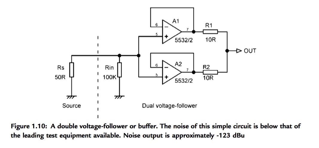
...before order somme discrete input buffer:
Diamond buffer board stereo broadband strong driving capability assembled ! - JIMS Audio

JFET input Cascoded buffer board assembled ! - JIMS Audio

DC Buffer Preamplifier Board Stero Opamp Preamp Circuit for NE5534 OPA627 AD847 699956627623 | eBay

I try to find a buffer suitable to improve the JLE/JLA... whichever source I plug-in I have noise ... and without source no noise...
I want to test a simple circuit....:
...before order somme discrete input buffer:
Diamond buffer board stereo broadband strong driving capability assembled ! - JIMS Audio
JFET input Cascoded buffer board assembled ! - JIMS Audio
DC Buffer Preamplifier Board Stero Opamp Preamp Circuit for NE5534 OPA627 AD847 699956627623 | eBay
Last edited:
Witch one are better ?
Need input cap on JLA for the JFET cascode and OP-AMP 5534 board ?
The Diamond are already an output cap...
Need input cap on JLA for the JFET cascode and OP-AMP 5534 board ?
The Diamond are already an output cap...
Last edited:
D
Deleted member 148505
Hi Lester. Interested in the IRCore2000 PCBs you're selling on Ebay. Do you have a rough estimate for cost of US sourced parts (Mouser, Digikey, etc.) per board? I have a chassis, power supply and heatsink, so just need to build a couple boards. Thanks.
Rough estimate is around 40 to 50 USD per ch.
These are the expensive parts:
1pc SETP-0805-100
2pc PRF18BC471QB5RB
1pc 3362P-1-201LF
1pc A750EK476M1EAAE040
4pc UVZ2A221MHD1TO
2pc 2SD882
2pc 2SB772
1pc AGP4233-223ME
4pc IRFB4227
1pc IRS2092S
2pc MUR460
3pc MUR120
Regards,
Lester
- Status
- Not open for further replies.
- Home
- Vendor's Bazaar
- Amplifier Modules and PCBs For Sale