Hi LC,
Have a suggestion for a good non SMD that could be leave on place after setup. It for my DIY single layer board.
Thanks Marc
Hi Marc
If understood correctly you want to design VSSA on single layer PCB. Or I do apologize to missed your point.


Ah noo, just found myself in a situation to complete what promised.You're a good and brave man LC.

Thanks Esperado. Probably only selling VSSA modules for a few moths and than the end of the story.L.C , i can see-you, in few years at the head of your big hifi company
200 !!!
Amazing. Congratulation, but what a work !
Will you include the little piggies?
No no no, pigs are there helping to get the rest of the ALFs soon hehe
Hi Marc
If understood correctly you want to design VSSA on single layer PCB. Or I do apologize to missed your point.
Hi LC,
It's always done (see file under). I juste want to replace parallele resistors by trimmer for definitiv...The board is single layer made with smd parts on copper side but that's not possible for trimmer...
Attachments
Through hole multiturn trimmers are OK to be left on PCB after set-up, they're very precise. You have enough space to add two trimmers for offset/VAS bias adjustment. Also you can replace all three trimmers with two parellel resistors afterwards, all combinations possible to make with your PCB.
Through hole multiturn trimmers are OK to be left on PCB after set-up, they're very precise. You have enough space to add two trimmers for offset/VAS bias adjustment. Also you can replace all three trimmers with two parellel resistors afterwords, all combinations possible to make with your PCB.
Ok thanks LC, will first built your piggies....
Marc
Ok thanks LC, will first built your piggies....
Marc
Yes in that order, SMD VSSA as a reference to beat.
Oh, I thougt those piggies were ment as a help holding SMD's down during soldering for us (only me?) who want to solder SMD's.
True, looks not many members wanted to solder SMDs manually, but I am sure you could replace some parts easily since they're not glued to PCB. Still many options opened, as always.
True, looks not many members wanted to solder SMDs manually, but I am sure you could replace some parts easily since they're not glued to PCB. Still many options opened, as always.
Hi LC,
It was a joke.
Thanks for the no glue info.
I want to reinforce what others have said, you've done a great job!
VAS bias v. Supply Voltage
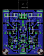
This relates to the through-hole version of the VSSA circuit, as presented in Shaan's PeeCeeBee thread.
http://www.diyaudio.com/forums/solid-state/231662-peeceebee.html
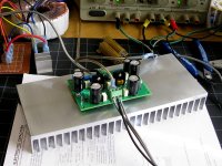
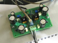
I am testing my layout of Shaan's circuit (pic attached), at a DC supply voltage of about +/-36V. I expect line and load variations of perhaps 35~37V DC. Offset and bias were set using two trimpots.
I have noticed a large change in VAS bias with fairly small changes in supply voltage. Over the same supply voltage range 35-37VDC, VAS bias current changes from 13.6~18.3 mA. 5% change in supply and 25% change in VAS bias current.
I would expect some of this because this is the circuit with a 15K instead of a CCS, but where is the rest coming from?
Test conditions are 35-37VDC, adjusted using a variac, no input (shorted), no load (open). Measured with Fluke 77 multimeter. (pictures show input and output connected, but the above results were measured as stated)
This relates to the through-hole version of the VSSA circuit, as presented in Shaan's PeeCeeBee thread.
http://www.diyaudio.com/forums/solid-state/231662-peeceebee.html
I am testing my layout of Shaan's circuit (pic attached), at a DC supply voltage of about +/-36V. I expect line and load variations of perhaps 35~37V DC. Offset and bias were set using two trimpots.
I have noticed a large change in VAS bias with fairly small changes in supply voltage. Over the same supply voltage range 35-37VDC, VAS bias current changes from 13.6~18.3 mA. 5% change in supply and 25% change in VAS bias current.
I would expect some of this because this is the circuit with a 15K instead of a CCS, but where is the rest coming from?
Test conditions are 35-37VDC, adjusted using a variac, no input (shorted), no load (open). Measured with Fluke 77 multimeter. (pictures show input and output connected, but the above results were measured as stated)
Attachments
This relates to the through-hole version of the VSSA circuit, as presented in Shaan's PeeCeeBee thread.
http://www.diyaudio.com/forums/solid-state/231662-peeceebee.html
I am testing my layout of Shaan's circuit (pic attached), at a DC supply voltage of about +/-36V. I expect line and load variations of perhaps 35~37V DC. Offset and bias were set using two trimpots.
I have noticed a large change in VAS bias with fairly small changes in supply voltage. Over the same supply voltage range 35-37VDC, VAS bias current changes from 13.6~18.3 mA. 5% change in supply and 25% change in VAS bias current.
I would expect some of this because this is the circuit with a 15K instead of a CCS, but where is the rest coming from?
Test conditions are 35-37VDC, adjusted using a variac, no input (shorted), no load (open). Measured with Fluke 77 multimeter. (pictures show input and output connected, but the above results were measured as stated)
That is right. 2V/15K = 134uA
470R*134uA = 63mV
63mV/10R (VAS emitter resistor) = 6.3mA.
Thanks for the help, should have been able to do that myself, but for some reason, NOTThat is right. 2V/15K = 134uA
470R*134uA = 63mV
63mV/10R (VAS emitter resistor) = 6.3mA.
hi LC
1) datasheet for ALF 8A shows max current. There will be better Zener diode 8V2? What happens if there is a short circuit at the output? Kaput? Alf or will live on? As it is short-circuit protected output? It could limit with the help 8V2 - there is a max current of about 8 A, ALF survive and destroy the fuse.
2) Can you give measurements 4R +1 uF / MKT parallel? Sine is up to MHz, rectangle is nice to 100kHz (hats off) but how it behaves on the capacitive load? At the output coil is not - it will be OK or not? I hope so, it's super amp
Last edited:
- Home
- Vendor's Bazaar
- VSSA Lateral MosFet Amplifier