I'm having some trouble with my maida regulator, and hoping someone here can help out. I'm currently using it to tinker around with the PSU of my bottlehead crack (new PT, maida reg, new caps... the whole works). The regulator is regulating the voltage to where I want, but the output ripple seems to be really high. There is a very clear 120hz hum coming through the headphones. To confirm it was PSU ripple, I added an LC filter after the maida reg, and the hum disappeared. From my understanding, the maida reg should produce extremely low inaudible ripple by itself. Anyone have ideas on why the ripple would be so high with just the maida reg?
For reference, I'm working with a 265-0-265V PT -> 5AR4 -> 33uF input cap -> maida reg -> 180V output voltage. Current draw from the amp is about 75mA. Also, I just discovered that no output cap is needed on the maida reg, so at one point I had several 100's uF on the output of the regulator (treating it like a pi filter). Could this have damaged it? I wouldn't think so, considering it still regulates the voltage properly...
Any suggestions would be great!
I was working on my own version of HV regulator when I came across this thread. First off: Thanks to Tom for all his efforts and sharing this.
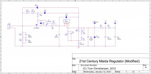
I inherited a KT88 parallel amp project (100W/ch) from a friend and the chassis work is already done as are the amplifier PCBs. I have very limited space for the HV reg, or I would probably use two of the Neurochrome modules; also, each channel will require ~550mA @380VDC and require B1+ and B2+ taps. I modified Tom's schematic a bit and each channel will have its own regulator and input filter caps. I changed the current limit resistor R3 to 0R5 with a HV NPN foldback transistor to limit current to ~1.25A. This also required a change to D2 from 10V->6V8. Because of space restrictions, I eliminated R8, C5 and D6 which are just for short circuit protection? Do you see any problems with my modifications?
I inherited a KT88 parallel amp project (100W/ch) from a friend and the chassis work is already done as are the amplifier PCBs. I have very limited space for the HV reg, or I would probably use two of the Neurochrome modules; also, each channel will require ~550mA @380VDC and require B1+ and B2+ taps. I modified Tom's schematic a bit and each channel will have its own regulator and input filter caps. I changed the current limit resistor R3 to 0R5 with a HV NPN foldback transistor to limit current to ~1.25A. This also required a change to D2 from 10V->6V8. Because of space restrictions, I eliminated R8, C5 and D6 which are just for short circuit protection? Do you see any problems with my modifications?
Attachments
I'm having some trouble with my maida regulator, and hoping someone here can help out. I'm currently using it to tinker around with the PSU of my bottlehead crack (new PT, maida reg, new caps... the whole works). The regulator is regulating the voltage to where I want, but the output ripple seems to be really high.
Sorry for the late response. For some reason I no longer get email notifications from this thread.
That usually happens if the valleys of the ripple voltage drops below Vout+15V.
What's your desired output voltage?
For reference, I'm working with a 265-0-265V PT -> 5AR4 -> 33uF input cap
Have you tried dropping that into PSUD-II and simulating it?
Also, I just discovered that no output cap is needed on the maida reg, so at one point I had several 100's uF on the output of the regulator (treating it like a pi filter). Could this have damaged it? I wouldn't think so, considering it still regulates the voltage properly...
Nah. It's fine. At lower voltages (and with the impedance of the 5AR4 rectifier) the Maida can handle more abuse. I do recommend that you let the regulator do its job and just have 10-20 uF as local decoupling in the amp circuit.
Tom
What's your desired output voltage?
Have you tried dropping that into PSUD-II and simulating it?
Tom
No worries, thanks for the response. The output voltage I want is 180V. The measured input voltage to the regulator after rectification and the 33uF cap is 414V, so well above the minimum requirement from your spreadsheet.
Do you mean modeling just the PT, 33uF cap, and 5AR4 in PSUD? If so, I'm getting 345 to 359V (about 13V ripple) after that input cap. Still well above the 15V drop out.
Oh, wow. Yeah. 350 -> 180 V should not result in hum on the output. Does it hum after you removed the 100s of uF on the output?
Tom
Yes, it still hums after removing all output capacitance. For sanity, I tried both the 5AR4 as well as a solid-state plug in rectifier. Both resulted in 350-360V input voltage.
Something interesting I discovered is that if I add an LC filter before the regulator, the hum is still there. But, if I add the LC filter after the regulator, the hum goes away. That's confusing...
Never mind, I found the answer on page 5: Page 5 Post 45
Made the room on the PCB for R8, C5 and D6. Good to go.
Made the room on the PCB for R8, C5 and D6. Good to go.
That's odd. It sounds like the regulator isn't working, but it provides the correct output voltage. That's really weird. How do you have the ground of the regulator connected?
Tom
Ground is connected on the ground side of the V_in connection on the regulator. Everything is set up outside the original amp, so the regulator's ground plus a few other ground wires (PT center taps, PT internal shield, caps if using the extra LC) are bussed together and connected to the star ground spot on the amplifiers original circuit.
Would you try measuring the AC voltage at the output of the regulator. That should register as 0 V on just about any handheld meter.
Tom
Yup, that measures 0V AC.
That would indicate that the hum is not caused by the Maida Regulator.
I think you mentioned that your setup was:
Transformer -> 5AR4 -> 33 uF -> Maida, but with a shared ground. Try separating the ground from the input to the Maida from the output. So basically you keep the transformer, rectifier, and reservoir cap separate and connect that to the Maida. Then connect the output of the Maida (including its ground) to the ground of the rest of the amp.
Tom
That would indicate that the hum is not caused by the Maida Regulator.
I think you mentioned that your setup was:
Transformer -> 5AR4 -> 33 uF -> Maida, but with a shared ground. Try separating the ground from the input to the Maida from the output. So basically you keep the transformer, rectifier, and reservoir cap separate and connect that to the Maida. Then connect the output of the Maida (including its ground) to the ground of the rest of the amp.
Tom
Aha, that fixed it! From just eye-balling the PCB, it looks like the grounds for v_in and v_out are connected together, so I assumed that I could just connect one or the other to ground. But using and separating the ground connections for both v_in and v_out fixed it. Thank you!
Yep. The ground on the Maida Regulator is connected from input to output. But the "dirty currents" are on the input side. Think of the ripple current through the 33 uF capacitor, for example. That needs to be kept away from sensitive circuits, such as the input/signal ground.
Anyway. I'm glad you got it working. Enjoy.
Tom
Anyway. I'm glad you got it working. Enjoy.
Tom
Just started researching power regulation over the weekend, and just stumbled over this thread.
Good to see a HV to a good 500mA. I'd started on (ie looking at FQPK3N60C which is DC safe zone for 100-400mA for 400 to 200V with an LM317), but this seems to align nicely.
As this is an OTL headphone amp, I'd want current limiting it and short-circuit trip. There's a scenario where if the output cap fails and shorts there is a 32ohm earth path through the parallel ecc99s to B+, bypassing the CCS. In total probably a total of 100mA per channel operating current (25mA at 200V and 75mA at 150V), but I want capacity for changes in future.
I've seen the use of a sense resistor after the pass element used for current sensing combined in other voltage regulator designs, with the LT holding the pass element, it would need a separate current limiter post voltage regulator I assume.
Last edited:
Source: High Voltage Regulators (Maida or zener)The prototype I threw together from the schematic/pcb in my post of yesterday actually works really well. It regulates fine with no load. However, it does not survive start-up into a low-impedance load. On the lab bench I use light bulbs for a load. Four 25 W, 120 V bulbs in series present 200-some ohms with cold filaments. If I bring the input voltage up slowly, the regulator works fine. But turn-on by the flip of a switch leaves me with $7 of dead silicon... Relying on the emitter/source resistor of the cascode to provide any current limiting function is not reliable. I may have to swallow my pride and use a discrete regulator...
This has got me thinking - I will have a back of smoothing caps on input and initially no conductance through parallel ecc99s until B+ kicks in, even with cathode pre-loading of bias (to have a known grid negative bias) on start, there's a 330uF output cap which essentially is low impedance on start. I just need to ensure that there's enough resistance (ie through valves) for this startup period?
The input and output of the amp will be relay muted, so it won't have a signal and a good 30V on the cathode bias as the B+ comes up. That way the valves should provide a level of say ~several K ohm resistance in parallel. The CCS on the output limits to 75mA from ground.
Also I take it that this wouldn't like running heater elements until warmed up? I will be current limiting these on start anyway to prevent euro-tube filament hotspots.
I'm a bit unclear what your question is and how it relates to the 21st Century Maida Regulator. I would love to help, but without a better grasp of how I can help I can't really say anything meaningful.
Tom
Hi Tom,
Have you considered the LT3081 - it has programmable current limit pin. Seems like a good option.
Nick
- Home
- Vendor's Bazaar
- 21st Century Maida Regulator