Hi Bandersnatch, if it can be of any help for your PP project, this SE thread started from this other thread about a PP amp with same characteristics:
Shunt Cascode Driver meets UNSET for Push-Pull
Shunt Cascode Driver meets UNSET for Push-Pull
George, when you tried the UNSET as a power amp for a guitar amp, do you have bypassed the bottom resistor of the a-g1 feedback with a cap to decrease the nfb at high frequencies like a "presence" control does? ThanksI use a mosfet circuit often called a gyrator in my guitar amp
I have experimented with a bypass cap and a pot in series for a variable presence control. This allows an adjustable set of curves from triode like to pentode, but the curves vary with applied frequency due to the cap. The pot also dissipates some AC power, and can get quite warm at high power levels.
An equivalent setup that works down to DC involves a bypassed fixed DC supply at the same voltage that would normally be seen on the grid, feeding a pot to the grid. Again, some audio power will be dissipated in the pot.
Most of my guitar amp experiments have been done on a small 20 watt push pull amp built with UNSET technology. That way the fireworks are minimized when things go wrong.
What can go wrong? Try sticking a tone stack in the feedback loop (OPT secondary to PI) of a typical Marshall style amp. The phase shift involved can make for a very high powered audio oscillator, but it sounds cool when run right on the edge of instability.
Thank you George, would you mind talking about it in a dedicated thread?
I can open it in the specific section of the forum and post what I'd like to do to open a discussion.
I've built alot of guitar and bass amps for me and friends, and I would like to blow some powder away from usual designs.
I can open it in the specific section of the forum and post what I'd like to do to open a discussion.
I've built alot of guitar and bass amps for me and friends, and I would like to blow some powder away from usual designs.
Since the cathode of the output tube is being driven in this amp, tying the screen to a fixed voltage (with respect to GND) will result in positive drive to the screen (with respect to cathode). I believe zintolo is attempting to make the voltage between screen and cathode stay more or less constant with the UL, and doing that has some advantages.
It is kind of similar to the Unity-Coupled amp in that respect, where the screen and cathode are moving around but following each other. This one is not quite as constant, though, since there is the tube's distortion added to the UL signal but not the cathode drive side.
So to follow this bit on k-g2 voltage, would it be 'better' to attempt matching up the FB and g2 voltage behaviour, or would setting the tap to deliver some U-L-ish performance? If the k-g2 voltage is looking like 9-11% U-L behaviour, would this be preferable to having it behave like a pentode with a +/-1% variation in the k-g2 voltage when this variation is set by some nonlinearity or another?
cheers,
Douglas
Hi Douglas,
thanks for the suggestion on a further test to be performed.
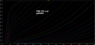
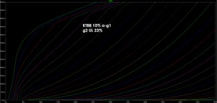
I have a pair of 4k Raa 23%UL PP output transformers, so I can set it to 23% a-g1 feedback to get an almost constant g2-k voltage or 10% a-g1 feedback and so have a 13% UL.
In the meanwhile I can post the curves simulated in LTSpice and we can discuss on it.
I'd say that with more UL would require higher voltage and higher Ra to have the same wattage and hit the "knee" as before (of course the "knee" goes down with UL). THD should be better, DF to be verified.
thanks for the suggestion on a further test to be performed.
I have a pair of 4k Raa 23%UL PP output transformers, so I can set it to 23% a-g1 feedback to get an almost constant g2-k voltage or 10% a-g1 feedback and so have a 13% UL.
In the meanwhile I can post the curves simulated in LTSpice and we can discuss on it.
I'd say that with more UL would require higher voltage and higher Ra to have the same wattage and hit the "knee" as before (of course the "knee" goes down with UL). THD should be better, DF to be verified.
So to follow this bit on k-g2 voltage, would it be 'better' to attempt matching up the FB and g2 voltage behaviour, or would setting the tap to deliver some U-L-ish performance? If the k-g2 voltage is looking like 9-11% U-L behaviour, would this be preferable to having it behave like a pentode with a +/-1% variation in the k-g2 voltage when this variation is set by some nonlinearity or another?
cheers,
Douglas
Why not connect g2 to K (for AC) would that not be a simple solution?
Jan
Why not connect g2 to K (for AC) would that not be a simple solution?
Jan
It would raise the drive voltage requirements a bit since drive would only applied between G1 and K along with the negative feedback.
In my implementations of this design the AC drive signal is applied to the cathode while negative feedback is applied to G1 via a resistive divider from plate to ground. This results in AC drive being applied to G1 and G2, while the feedback is applied to G1 only.
This scheme was the result of nearly 10 years of tinkering on a breadboard prototype where the cathode, G1 and G2 each had a mosfet pair connected to it so current could be sourced or sunk into or out of the pin. Each pin could receive a variable DC voltage and AC drive of either phase from a push pull driver board.
90% of my initial testing was done on a 6KD6 TV horizontal sweep (line output) tube. Large TV sweep tubes of this kind will fail if run in a typical triode connection due to their low G2 voltage rating and rather sensitive screen grid. The goal of my experimentation was to find a method to get triode like performance from the big sweep tubes, preferably without a complex power supply. After finding some possible paths to success I began to simulate some of these designs in LT spice.
The scheme that I posted in the UNSET / CED design appears to generate near perfect triode curves on most big sweep tubes. This has been demonstrated in LT spice, and real measurements on the bench. Again, most of my work has used TV sweep tubes. Their screen grid characteristics are quite different from those of a typical audio tube.
I have run a few simulations with some of the typical audio tubes, and I have stuck some KT88's into my amp to verify that they will work. In all cases the screen was simply tied to a fixed (WRT ground) voltage supply.
This thread has been about trying some UL type stuff with G2 and most of the tubes I have seen mentioned are typical audio tubes. I have not done enough testing with them to know what to expect.
One of the (real bench) experiments planned for the near future will test a 6V6GT, a 6K6GT and a 6W6GT against each other. The 6V6 is a beam power tube, the 6K6 is a true pentode, and the 6W6 is a beam power tube of similar size with a high powered cathode and a sweep tube style screen grid. I suspect that each will need a different G1 feedback ratio, and possibly a different G2 connection for optimum operation.
Last edited:
Z, your fixed voltage on g2 will deliver a positive FB, yes? It seems the near constant k-g2 voltage when U-L tap is the same as the FB ratio keeps it 'a pentode to modify with FB', and here we might wish to employ bi-filar windings to deliver the big sweep tubes a lower g2 voltage vs the plate, and then keepk-g2 near constant by winding the OPT the same as the FB ratio.
It could be that the 'U-L source follower/approximator' would be just as effective...I probably missed a critical bit from George...")
cheers,
Douglas
It could be that the 'U-L source follower/approximator' would be just as effective...I probably missed a critical bit from George...
cheers,
Douglas
Hi Douglas,
thanks for the suggestion on a further test to be performed.
I have a pair of 4k Raa 23%UL PP output transformers, so I can set it to 23% a-g1 feedback to get an almost constant g2-k voltage or 10% a-g1 feedback and so have a 13% UL.
In the meanwhile I can post the curves simulated in LTSpice and we can discuss on it.
I'd say that with more UL would require higher voltage and higher Ra to have the same wattage and hit the "knee" as before (of course the "knee" goes down with UL). THD should be better, DF to be verified.
Sounds like a fine plan. I have a pair of BO14 outputs, and they have 33% taps along the plate winding, and a tertiary coil of 10%...it seems these might be more useful than I have suspected of late...
To split a hair or two, with this AC conversion of the plate curves to those of a triode, the 'knee' is not su much a knee, but an upper limit on the plate curve current. The load line is no longer so critical with its need to navigate the effects of the knee. To deliver more voltage output, the g2 voltage needs to be high enough to allow load line passage to a low enough plate voltage( at what ever current is required ).
I recall some of the writings on 'Crazy Drive', where the g1 got a signal 1/triode-mu compared to the primary drive applied to the screen. Soooo...it could be that a U-L percentage that delivers this proportional increase to g2 voltage will turn up an interesting sweet spot...
cheers,
Douglas
Last edited:
Due to the deep swing of the cathodes in this configuration and the h-k limitations of the tubes, I'm thinking to derive both bias and heater elevation from B+, with the same RC timing (so they raise together) and a 5RC lower than 10 seconds (approximately the turn-on time for the tubes IME).
What do you think?
What do you think?
I would offer perhaps a single split bobbin power transformer for each power tube. Connect the center tap to the cathode with a 20kOhm resistor. It will be like Mary's little lamb, where ever she goes, the lamb was sure to follow.
cheers,
Douglas
Or just run directly heated...
cheers,
Douglas
Or just run directly heated...
I use a single SMPS for all output tube heaters. The driver tubes run from a single 6.3 volt source, which in my case is ground referenced.
The SMPS for the output tubes is referenced to the average value of both cathodes with a 10K resistor to each cathode and a cap to ground. Modern TV sweep tubes have a fairly high H-K breakdown rating which will not be violated in an average music situation in an SE amp.
Driving both channels to clipping with out of phase sine waves may be a different story if the feedback ratio is cranked up in and effort to kill all distortion. I am driving both channels out of phase in my P-P version of the UNSET, and full power (250 watts) testing with sine waves has not been a problem at the 10% feedback level.
Thanks George! I'm slowly going on with this project and your suggestions are really gold for me. If I've interpreted your 10% suggestion correctly, that amount of feedback permit to have triode-like curves, acceptable damping and an amp that gradually a nicely goes into saturation, whilst higher a-g1 feedback ratios would give a cleaner sound but then suddenly too much distortion when overloaded, so overall a less pleasant sound on peaks.
Douglas, thanks for that trick! Very simple and effective!
Douglas, thanks for that trick! Very simple and effective!
In the meanwhile I can post the curves simulated in LTSpice and we can discuss on it.
Attachments
zintolo,
I love those curves you posted.
I especially like the first one, because it shows curves that are:
Convex
Straight
Concave
Results will vary according to the portion of those curves that are used.
A nice resistive loadline can be picked to make it all linear . . .
And then a problem appears, many loudspeakers present an elliptical load.
Now, the elliptical load gets us in all three areas, convex, concave, and straight curves.
Forget about worrying about damping factor, that is the least of the problems.
Because of the elliptical load, I am not using that set of curves without negative feedback to do some rudimentary 'fixing' of the 'load problem'.
Thanks for your intervention 6A3sUMMER,
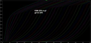
those curves have been posted exactly to discuss about them so your post is very welcome. I will add the curves I suggested at the beginning of this thread to compare them. One point you just suggested me is to post 23% a-g1 curves without UL, so same triode-like curves with a wider area of parallel curves around the loadline to help keeping linearity with ellipsoid loadlines.
What speaker parameters affect the ellipse? What makes it wider or more "straight loadlinean"?
Thanks
- Home
- Amplifiers
- Tubes / Valves
- Single Ended: the pentode retaliation