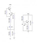
Why not keep it modular? I build these CCS on 5x8 holes Vero Board with leads soldered in place. Keeping wires short fixates it enough, no dangling around. Simply build your circuit hard wired and add these circa 2cmx1cm boards. Most efficient if you want to alter a setup. I never use fuses besides the mains fuse.
Attachments
Last edited:
Like in First stereo tube amp build advice
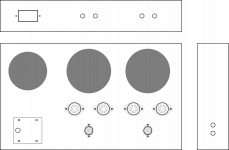
Currently I'm thinking modular at a bit higher level. The chassis, power supplies and OT's should enable some audio circuits. The audio circuits are (will be) on a exchangeble pcb.
If I'm going to change it...
Currently I'm thinking modular at a bit higher level. The chassis, power supplies and OT's should enable some audio circuits. The audio circuits are (will be) on a exchangeble pcb.
If I'm going to change it...
Hi Tom,
I'm aligned with your idea of keeping it modular at a higher level. Reusable sub assemblies are also interesting, but a modular approach fits nicely with testing: PSU, Channel 1, Channel 2.
Have you had any thoughts on connectivity? Most people seem to use the on-board screw connectors, that come in 2's or 3's and plug together if necessary. That is OK, but when disassembling, there is always a risk wires will be loose or in the wrong place when reconnecting. I was quite keen on some inline connectors, so colour coded wires have to match when reconnecting, to eliminate any error (a bit like the connectors on the back of a car radio). But when I look for something suitable there are just so many options, I am bamboozled.
Marc, designer of the PCB solution for the BH, used Molex connectors in some places, and they look interesting, but I am not sure if crimping is OK in a tube amp, and the tool is also quite pricey.
Does anyone use soldered in-line connectors? I'm looking for 2, 3 and 5 wires per connector.
Cheers, Richard
Not that luxurious versionLike in First stereo tube amp build advice
Currently I'm thinking modular at a bit higher level. The chassis, power supplies and OT's should enable some audio circuits. The audio circuits are (will be) on a exchangeble pcb.
If I'm going to change it...
") I use the simple island type because there are just five parts on the board. Keeping it small allows you to place it spot on target. A large board consisting of many circuits brings added parts coupling while long(er) runs of wire are needed, interacting with existing electrical fields. Just an opinion
I use the simple island type because there are just five parts on the board. Keeping it small allows you to place it spot on target. A large board consisting of many circuits brings added parts coupling while long(er) runs of wire are needed, interacting with existing electrical fields. Just an opinion Agree with modular PCB & chassis-
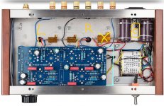
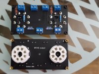
We hobbyists tend to change things frequently, so using similar size PCB w/ external wiring same areas allows easy switch out future designs.
I've had 3 different designs in my ChiFi chassis... soon to be 4
Jim
We hobbyists tend to change things frequently, so using similar size PCB w/ external wiring same areas allows easy switch out future designs.
I've had 3 different designs in my ChiFi chassis... soon to be 4
Jim
Attachments
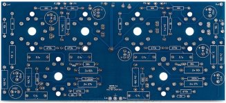
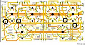
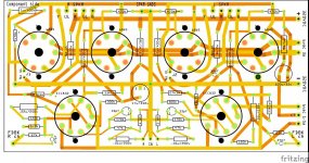
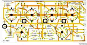
I'm making a module amp design. Pick your VA/PI, decide if you need the driver, and pick your output boards. So far, the output boards will work with about 30 different types of tubes including 6CK pinout like 6AV5, 6L6 and all the other tubes with that pinout including 6BQ6 and 6P31S with top caps, 6KG6, 6P36 etc.
Here's a picture of the 6P31/6L6/6V6/KT*/6BQ6 etc board front and back. The jumpers enable pin 3 as plate, or tying 1 to 8 for EL34.
Koda
Here's a picture of the 6P31/6L6/6V6/KT*/6BQ6 etc board front and back. The jumpers enable pin 3 as plate, or tying 1 to 8 for EL34.
Koda
Attachments
Hi Tom,
I'm aligned with your idea of keeping it modular at a higher level. Reusable sub assemblies are also interesting, but a modular approach fits nicely with testing: PSU, Channel 1, Channel 2.
Have you had any thoughts on connectivity? Most people seem to use the on-board screw connectors, that come in 2's or 3's and plug together if necessary. That is OK, but when disassembling, there is always a risk wires will be loose or in the wrong place when reconnecting. I was quite keen on some inline connectors, so colour coded wires have to match when reconnecting, to eliminate any error (a bit like the connectors on the back of a car radio). But when I look for something suitable there are just so many options, I am bamboozled.
Marc, designer of the PCB solution for the BH, used Molex connectors in some places, and they look interesting, but I am not sure if crimping is OK in a tube amp, and the tool is also quite pricey.
Does anyone use soldered in-line connectors? I'm looking for 2, 3 and 5 wires per connector.
Cheers, Richard
Currently I'm thinking of soldering. I assumed any screw connectors would be a no go. Little to no experience, so I can't advice you.
I'm open to suggestions.
The resistor type of choice for high power applications is wirewound.
Wirewound resistors do have higher inductance than film resistors.
However, in the 'tail' of a LTP (the cathodes) inductance won't matter. Actually, you could use an inductor there to act as a sort of current source. Of course a MOSFET can be made with much higher impedance to act as a *constant* current source, so all the better. But still, that goes to show you that inductance is not an issue there.
Have you read Morgan Jones "Valve Amplifiers"? These issues are covered in good detail there.
Valve Amplifiers - 4th Edition
I've read both of his books in the mean time. I like the design book much better.
The design/research phase of the amp is coming to an end. I actually made my first order today. Still researching a grounding scheme. rayma pointed me to a presentation that is a bit over my head. In other threads I saw a post of you rongon and suddenly it struck me: I think I know where you got your avatar :-D
https://worldradiohistory.com/Archive-Rider/BOOKS/Inside-the-Vacuum-Tube-Rider-1945.pdf
Thanks for all the help so far. I'll start a new thread for the build.
- Status
- This old topic is closed. If you want to reopen this topic, contact a moderator using the "Report Post" button.
- Home
- Amplifiers
- Tubes / Valves
- First stereo tube amp build advice