Thanks, I would appreciate normally, then you have the same age of my father, so I appreciate twice. I'm a Mec. Eng. and as a passion I always chase different nuances of distortion from guitar amps, but this is the first time I try to design a bass amp from (almost) zero, and thanks to this forum I've learned really alot, and I know I still will. Thanks!Its aimed at the many newbies & others making there way here, hopefully to something that works without smoke.
I've just found this one, at the moment. I will keep on searching.There were several articles on hybrid circuits tube outputs driven by SS over a period of time, some looked very good.
https://www.keith-snook.info/wirele...76/Transistor driver for valve amplifiers.pdf
Thanks for the explanation, well noted. Can we consider the total output impedance of the PI around 40 kOhm? So with 100 pF a -3dB point at 40 kHz?Ciss is not a big deal in a follower since the source follows the gate so that these two electrodes are nearly at the same potential all the time. Crss (gate to drain) capacitance is the critical spec on a follower, and these run about 30 pF each. You need a driver that will see about 100 pF most of the time. Not too hard, but 12AX7's need not apply.
Off topic: Funny, this is the other thing I'm simulating with this shunt feedback idea. 15 years ago, together with two friends (one Italian, one in the USA) I realized an amp that was a modified Soldano preamp into a modified Marshall 1959 power amp. We called it Marsholdano, and you can hear my bad playing here, without any EQ nor compression nor fx: Marsholdano by roberto-31 | Roberto 31 | Free Listening on SoundCloud ).I will eventually fill the remaining empty space on the perf board with a guitar preamp and this will become a little guitar amp.
Now I proposed to both my friends (Joey Nazari and Sebastiano Barbirato) to build a new version of it. Joey came out with a simple but very effective design adding two 12ax7 stages in parallel, cold biased, after a plexi preamp, to very well mimic PA and OT dimed. My idea is to implement it into a "Marshall Major meets 2020" power amp, substituing the UL taps with shunt feedback à la Baby Huey, including powerdrive, with less power and weight than the original "monster". EL84 as a first choice, with the possibility to have octals too. This could become a good and cheap kit for newbies too, with reasonably low voltages (around 300 V B+).
Third project I would like to see, even if it doesn't fit my tastes, is a Mesa Rectifier-like amp in raw-mode but with shunt feedback on PA: good damping but no feedback on the PI, so more harmonics at low volume, and tight on low strings.
...I think I just got bored of seeing two options on instrument amplification:
- copy paste of same old designs;
- digital emulations.
Last edited:
I've just found this one, at the moment. I will keep on searching.
https://www.keith-snook.info/wirele...76/Transistor driver for valve amplifiers.pdf
Thankyou for that link, an interesting amplifier. In my haste to post that request I forgot to mention the amplifier article covered PP tubes driven thru their cathodes by MOSFETs. Think there were a few guitar amps built that way as well.
I've searched here: WIRELESS WORLD: UK technical magazine 1913-2005
but I've not found them. In any case over there there are most of the issues scanned in very good quality.
but I've not found them. In any case over there there are most of the issues scanned in very good quality.
I forgot to mention the amplifier article covered PP tubes driven thru their cathodes by MOSFETs. Think there were a few guitar amps built that way as well.
John, do you recall if the Mosfets were used as followers (source connected to cathode, P-channel Mosfet) or as cascodes (drain connected to cathode, N-channel Mosfet)?
The N-channel cascode version would give "transistor sound" since the transistor gm determines the current flow, while the P-channel follower would give "tube sound" with the tube gm determining current flow.
By the way, one could use an N-channel Mosfet to drive the cathode as a follower using a CCS-tail with a differential (Mosfet with the tube) configuration. More parts, and class A only though. Not likely to get used much.
All I recall was thinking the circuit made a lot of sense. I'll try simulating something in the next day or so.
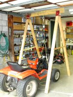
I've been on the run this spring & summer, there is a lot to do here on the 4.4 Acres (2 hect). One of the recent projects was changing the starter on an oversized Gilson garden tractor. The only way I could make the swap was by lifting the engine out.
The engine is a 2-cylinder opposed Briggs & Stratton with a difference, the crank is horizontal, not vertical as you see on most garden tractors. the electric PTO clutch is on the front & drive shaft to Eaton hydraulics & transmission to the rear.
Also have a Kubota Diesel, 3-cylinder. The crank is 240 degrees, so even firing.
Burned a lot of scrap here today, many dead & dying Ash trees. It sure was hot!! If I make it to the beginning of September I'll be 88. Still in pretty good shape so far.
I've been on the run this spring & summer, there is a lot to do here on the 4.4 Acres (2 hect). One of the recent projects was changing the starter on an oversized Gilson garden tractor. The only way I could make the swap was by lifting the engine out.
The engine is a 2-cylinder opposed Briggs & Stratton with a difference, the crank is horizontal, not vertical as you see on most garden tractors. the electric PTO clutch is on the front & drive shaft to Eaton hydraulics & transmission to the rear.
Also have a Kubota Diesel, 3-cylinder. The crank is 240 degrees, so even firing.
Burned a lot of scrap here today, many dead & dying Ash trees. It sure was hot!!
If I make it to the beginning of September I'll be 88. Still in pretty good shape so far.Attachments
I've searched here: WIRELESS WORLD: UK technical magazine 1913-2005
but I've not found them. In any case over there there are most of the issues scanned in very good quality.
THX for looking, that link is a very good resource. I've used it also, primarily checking for articles in Audio Engineering magazine. It was very popular & informative in the mid 50s when I was a lot younger. The R&D lab I worked in had a subscription so was well read by all the guys working there.
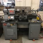
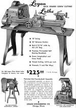
Several of the better paid staff were building Williamsons, they could afford to buy the very expensive Partridge OPT. Eventually I did buy a competitive Hammond OPT, one of their 1700 Series. But never built a Williamson. Too many stages & two many phase shifts, it had low frequency instability, sometimes difficult to cure.Working on restoring a Logan/Montgomery Wards lathe here, my father had it. Still missing a few small pieces, Ebay has been quite helpful. I think it dates from the 50s, just like tubes. The bed weighs around 150 lbs alone, 400 lbs all put together. The bed was stored on end in the kitchen of the apartment I was in before, and the floor started sinking. When the landlord started raising the rent, I decided it was time to buy a house with a big basement.
Now a lathe bed could make a nice chassis for a retro steam-punk amplifier or radio. They have them on Ebay. Just build it so it doesn't need servicing or moving .. ever. Well, the tubes can plug-in. Even better for a radio, let the carriage crank do the tuning.
I've seen some China import lathes lately for $650 or so, they have plastic gears. A U tube video shows how to machine new metal ones.
Attachments
I don't know if you read the previous part of the thread, but I decided (well... better to say "tried") to avoid the classical configuration with an extra stage between PI and output tubes. I'm very curious to know how it will sound... and also how it will become at the end, as it is changed alot since the beginning of the thread.Never built a Williamson. Too many stages & two many phase shifts, it had low frequency instability, sometimes difficult to cure.
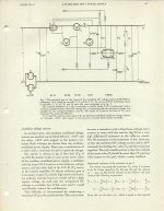
Driving an Audio Power Tube Cathode with a FET
Here is one solution, there are most likely many others. This has as its origin in an article in the Philips Journal of around 1960 on improving a photo multiplier HV PS. The Stabilization Factor of a vacuum tube PS is given by
S = uAK, where u is the passer tube mu, A is the gain of the error amplifier & K is the portion of the output sampled referred to the error amp. The value of K would be small, high stability standards such as the 85A2 were common. So 85 Volts was compared to perhaps 1.5 KV.
The paper covered how an NPN transistor could be used to greatly increase the apparent u of the passer tube. That way S could have a reasonable value.
Much later I tried simulated various versions of regulated PSs using an IRF 840 in the cathode of various power tubes. A regulated PS circuit is a SE amplifier, it follows its standard voltage as an input. So the circuit posted was developed from one of those PS circuits.
Don't see any advantage, others might.
John, do you recall if the Mosfets were used as followers (source connected to cathode, P-channel Mosfet) or as cascodes (drain connected to cathode, N-channel Mosfet)?
The N-channel cascode version would give "transistor sound" since the transistor gm determines the current flow, while the P-channel follower would give "tube sound" with the tube gm determining current flow.
By the way, one could use an N-channel Mosfet to drive the cathode as a follower using a CCS-tail with a differential (Mosfet with the tube) configuration. More parts, and class A only though. Not likely to get used much.
Here is one solution, there are most likely many others. This has as its origin in an article in the Philips Journal of around 1960 on improving a photo multiplier HV PS. The Stabilization Factor of a vacuum tube PS is given by
S = uAK, where u is the passer tube mu, A is the gain of the error amplifier & K is the portion of the output sampled referred to the error amp. The value of K would be small, high stability standards such as the 85A2 were common. So 85 Volts was compared to perhaps 1.5 KV.
The paper covered how an NPN transistor could be used to greatly increase the apparent u of the passer tube. That way S could have a reasonable value.
Much later I tried simulated various versions of regulated PSs using an IRF 840 in the cathode of various power tubes. A regulated PS circuit is a SE amplifier, it follows its standard voltage as an input. So the circuit posted was developed from one of those PS circuits.
Don't see any advantage, others might.
Attachments
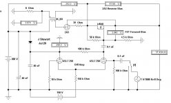
Regulated PS, The Starting Point
For the curious & others this DC PS Regulating circuit was the starting point for that FET driving the cathode of a power amp. All based on the circuit published by Philips in 1964. I did several simulations in 2004 looking at the practicality of such an arrangement for a lab supply. But never built, I already had something that was more than adequate for what I was doing. Still is!
Still interesting, NTL.
Attachments
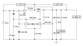
The 250 is part of the 6SL7 label I put in Electronic Workbench, I used the data sheet specs at 250V. Often the data sheet includes specs at other voltages, say 100V. So I would include that model in the list, that way the simulation could be run at a condition closer to the real thing if necessary.
BTW, I enjoyed Munich several times while with R&S in Canada. Took a Mountain Bike with me one time, a great way to see the city. Took the S-Bahn down to Starnberger & rode the bike around Starnberger See. Passed by the Amperewerk on the other side. And brought my wife on one trip, so we were tourists for another week.
BTW, I enjoyed Munich several times while with R&S in Canada. Took a Mountain Bike with me one time, a great way to see the city. Took the S-Bahn down to Starnberger & rode the bike around Starnberger See. Passed by the Amperewerk on the other side. And brought my wife on one trip, so we were tourists for another week.
Just as an update, I've done some simulations of the p-mosfet cathode-driven idea in a SE amp using some vacuun tubes I've found in my parent's house. Results are here: What can I do with them? 4x 1L4, 1x 6AQ5, 3x 6BQ5, 1x 6SN7
Still doing some simulations with this GU50 amp trying to improve it.
Still doing some simulations with this GU50 amp trying to improve it.
Another Look
The GU50 has a max dissipation rating of 40 watts. So with six in PP the total would be 240 watts. 450 watts of audio is unlikely without exceeding the dissipation max. Much of the performance data given on the specification sheets for the GU50 relates to Class C operation at radio frequencies.
Off the top a Class B PP audio amp gets about 60% efficiency.
Please excuse if someone has already made this point.
Thanks jhstewart9, Wavebourn uses GU50s with 850V B+ and Raa 10k, while es345 used them with 950V B+ and Raa 6k. I'm using them with a value inbetween: 900V B+ and Raa 7k5. Yes, it goes above dissipation limits for part of the swing, but as far as I've read from other users, GU50s can support it well, and it's quite typical for instrument amplification to have lower Raa than the ones suggested in the datasheet.
May I ask if you have a LTSpice model for it? Thanks!6EJ7 may work for you too - these I have used as a LTP phase spitter but they are max 250v plate. There's quite a selection.
- Home
- Amplifiers
- Tubes / Valves
- 450W bass amp: a sextet of GU50s with shunt¤t feedback