I've substitued the 12ax7 with the russian 6N2P-EV following the datasheet that can be found here: http://www.radiotechnika.hu/images/6N2P-EV.pdf
I've modified the model by keeping the curves the same and modifying capacitances only, as written in the model below.
I've modified the model by keeping the curves the same and modifying capacitances only, as written in the model below.
Code:
*
* Roberto's note: 6N2P-EV model based on:
* Generic triode model: 12AX7
* Copyright 2003--2008 by Ayumi Nakabayashi, All rights reserved.
* Version 3.10, Generated on Sat Mar  8 22:41:09 2008
* Roberto's note: modified following [url]http://www.radiotechnika.hu/images/6N2P-EV.pdf[/url]
* Roberto's note: input capacitance CGK = 2.35 pF
* Roberto's note: output capacitance CAK = 2.5 pF
* Roberto's note: transfer capacitance CGA = 0.55 pF
*               Plate
*               | Grid
*               | | Cathode
*               | | |
.SUBCKT 6N2P-EV A G K
BGG   GG   0 V=V(G,K)+0.59836683
BM1   M1   0 V=(0.0017172334*(URAMP(V(A,K))+1e-10))**-0.2685074
BM2   M2   0 V=(0.84817287*(URAMP(V(GG)+URAMP(V(A,K))/88.413802)+1e-10))**1.7685074
BP    P    0 V=0.001130216*(URAMP(V(GG)+URAMP(V(A,K))/104.24031)+1e-10)**1.5
BIK   IK   0 V=U(V(GG))*V(P)+(1-U(V(GG)))*0.00071211506*V(M1)*V(M2)
BIG   IG   0 V=0.000565108*URAMP(V(G,K))**1.5*(URAMP(V(G,K))/(URAMP(V(A,K))+URAMP(V(G,K)))*1.2+0.4)
BIAK  A    K I=URAMP(V(IK,IG)-URAMP(V(IK,IG)-(0.00058141055*URAMP(V(A,K))**1.5)))+1e-10*V(A,K)
BIGK  G    K I=V(IG)
* CAPS
CGA   G    A 0.55p
CGK   G    K 2.35p
CAK   A    K 2.5p
.ENDSThis is another version that will simplify the supply of the phase inverter.
Plate load is 2k4 and UL is always 20%, but now shunt is just 2%.
This specific version is not for Hi-Fi, but strictly for instrument amplification.
Plate load is 2k4 and UL is always 20%, but now shunt is just 2%.
This specific version is not for Hi-Fi, but strictly for instrument amplification.
Code:
Harmonic	Frequency	 Fourier 	Normalized	 Phase  	Normalized
 Number 	  [Hz]   	Component	 Component	[degree]	Phase [deg]
    1   	1.000e+03	9.804e+01	1.000e+00	    5.75°	    0.00°
    2   	2.000e+03	8.452e-01	8.621e-03	  -78.36°	  -84.11°
    3   	3.000e+03	6.901e+00	7.039e-02	   18.54°	   12.79°
    4   	4.000e+03	5.270e-02	5.376e-04	  -78.72°	  -84.47°
    5   	5.000e+03	5.878e+00	5.996e-02	 -148.24°	 -154.00°
    6   	6.000e+03	2.655e-01	2.709e-03	  133.24°	  127.49°
    7   	7.000e+03	2.019e+00	2.060e-02	 -131.16°	 -136.91°
    8   	8.000e+03	1.115e-01	1.137e-03	  154.20°	  148.45°
    9   	9.000e+03	7.825e-01	7.981e-03	   49.46°	   43.71°
Total Harmonic Distortion: 9.550485%(9.559542%)
Attachments

I would like to ask some suggestion on the power limits of the output tubes with the latest configuration:
As for the screens, at 10% THD, thanks to the 20% UL (so the fact that screens are going down together with the plates), looking at the simulation the screen dissipation is just 2,5 W while the limits for GU50 is 5 W, so it's ok.
Plate dissipation is 40 W continuous and 50 W for 1 minute.
At full signal and 10% THD we are inside the specs with 35 W, but in worst case scenario we reach up to 55 W. Proper forced ventilation can help to keep GU50 working properly? I remember es345 working with 950 V B+ and 2k Raa without issues, so it should be ok, but I would like to have some confirmation.
Then last but not least g1. Simulations say it will go from -15 to +15 uA and -150 to +35 V. Average dissipation 5 uW but this IMHO is a limit of the model and should be verified in reality. Limit is 1W.
Envelope temperature limit is 200 °C.
Thanks,
Regards
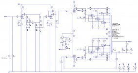
I've done some more simulations after this post of Tubelab: G2 using MOSFET ultralinear feed
The schematic is attached and, considering the full amp, preamp included, I get 540 Wrms at 10% THD.
Local shunt feedback applied with voltage divider plate to grid to ground, 330k 33k. 900V on the plates, 300V on screens, +103V bias (yes, positive), grid driven (I need to add the protection zener), Raa 2k7, no GNFB, positive current feedback from speaker to PI.
Attachments
I would use a separate mosfet for each output tube. This way each tube gets it's own bias adjustment for easier matching and there are less worries with SOA issues in the mosfets.
Peak tube currents in a big amplifier can go over 1 amp per tube into a reactive speaker load, and bad things happen in this design if a mosfet shorts out (their usual failure mode). I have seen a medium size TV sweep (line output) tube explode when the mosfet shorted during a curve tracing experiment.
I am now using FQPF9P25's in a single ended amp that can do 40 watts on 500 volts of B+ with no issues. Experiments with 6 X 36LW6's at 500 WPC were successful. I will be testing 4 X 36LW6's at the same power level soon.
Thank you very much Tubelab,
yes I've simulated one single mosfet, but I will follow your suggestion. As a pro-memoria, here it is the datasheet of the mosfet you suggested: https://www.mouser.com/datasheet/2/149/FQPF9P25-110839.pdf
Also, due to the impossibility to find matched GU50s, I will implement this autobiasing scheme posted by bandol83: https://www.diyaudio.com/forums/att...182310-el34-baby-huey-amplifier-kt120-sch-pdf
and your suggestion of one moster per tube comes handy.
Peak current in this case is around 600 mA each tube.
Is there any simple way to limit the current in case of shortage of the mosfet?
Well... without it it could be the perfect amp to play on new year's day... three, two, one... 😀
Local shunt feedback applied with voltage divider plate to grid to ground, 330k 33k. 900V on the plates, 300V on screens, +103V bias (yes, positive), grid driven (I need to add the protection zener), Raa 2k7, no GNFB, positive current feedback from speaker to PI.
I can no nome modify it, but it's of course cathode driven, not grid driven.
Best do a 'Proof of Concept' first with a single pair of output tubes. Will help to avoid many problems later. Doesn't need to look like a work of art. Can be a very rough build, some parts will probably need adjustment.🙂
Simulations are just that, usually based on small signal parameters of the circuit components. A simple hardware build will point in the correct direction.😱
Simulations are just that, usually based on small signal parameters of the circuit components. A simple hardware build will point in the correct direction.😱
I would use a separate mosfet for each output tube. This way each tube gets it's own bias adjustment for easier matching and there are less worries with SOA issues in the mosfets.
That would mean six individual hybrid cascodes in this case?
Driving the cathodes of basically grounded grid power tubes eases individual bias adjustment of each tube, as there's only need for individual grid DC voltage settings.
Btw, Music Man has done the same thing with their very early amplifiers: They were hybrids, as the small signal sections were SS throughout, and the finals (mostly 6CA7's in those days) were cathode driven, but with BJT's instead of MOSFETs.
Best regards!
Music Man has done the same thing with their very early amplifiers:
I found out about the Music Man amps late last year. They used a NPN BJT in common emitter configuration in the cathode of some 6L6GC's or EL34's. The amps had a characteristic "sound" that some people liked, and some hated.
I remember fixing one of them a long time ago. It looked like a lightning bolt had danced around one of the output tube sockets. Once I had cut away the burnt stuff and fixed the blown power supply, I figured out that the fire had started INSIDE the base of one of the 6L6GC's. That amp had over 700 volts on the plates of the output tubes.....POOF! i had no schematic at the time and didn't figure out that the transistor was in series with the tube, or did, but forgot all about it. Somehow the OPT survived the fireworks.
Best do a 'Proof of Concept' first with a single pair of output tubes.
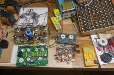
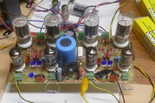
I always do a small scale proof of concept with cheap expendable tubes. In this case my Proof Of Cconcept runs a pair of $1 6GF5's per channel, driven by another pair of $1 6KT6 tubes.
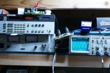
The flying wire and components creation (on the right of a Tubelab SPP board) made with an experimental driver board and a piece of perf board was the initial POC. It proved promising enough to create a one off PC board design (seen above the SPP board). The SPP is a conventional Simple Push Pull amp running a pair of EL84's for 15 to 25 watts depending on how hard you want to flog the output tubes. The POC board is not much larger than the SPP, but makes 50 WPC with a regulated 450 volt supply, and 80 WPC @ 2.9% THD with an Antek toroid that makes over 550 volts at idle, and about 500 volts at full crank (both channels driven to 80 watts). The pictures were taken with both channels at 80 watts for several minutes.
This board first saw power in July of 2018. It is still running fine with the same set of tubes in it. The output stage is solid, the driver has problems and is being redone. The driver stage is too picky about it's operating point. This was not seen when powered by the regulated supply, but noticed when powered with a cheap Antek toroid where the B+ varies almost 50 volts from idle to full load.
I started building tube stuff around age 10 using parts that I got from junk B&W TV sets. The most common "power tubes" in my collection were the 6BQ6 and the 6DQ6. I would not understand things like bias, impedance, or load lines for several more years, so it remained a mystery why the smaller 6BQ6 could crank out power, while the much bigger 6DQ6 just glowed red and made distortion and burnt parts. I made it a several year mission to conquer that 6DQ6.
You see a picture of three tubes. The internal guts of all three are the same. The two on the right are IDENTICAL, while the small one on the left has its "wings" clipped to fit in a small envelope. The tube on the right is a 6DQ6. The middle one is a 6GE5, and the little guy is a 6GF5, so if I can squeeze 80 watts from a pair of the little guys, I HAVE CONQUERED the 6DQ6. In case you are interested, yes I stuffed a pair of 6GE5's in the board and cranked up the B+. 110 watts per pair is easy. Trying to go beyond that makes the mosfets too hot for comfort.
I am working on a test board for bigger tubes. It will be an octal output stage for pairs of almost any octal tube. It is patterned after the matrix connection scheme used in the single ended UNSET.
That would mean six individual hybrid cascodes in this case?
That's my plan. yes it would be possible to use one big fat mosfet to feed any number of tubes with individual G1 or G2 voltage adjustments to match up tubes. This would subject the mosfets to peak currents approaching 3 amps in a 500 watt amp. A reactive load could create conditions where this current could occur with considerable voltage across the device leading to a secondary breakdown effect.
Yes, second breakdown is real in mosfets, although it has a different name, and is far more unpredictable. We fought this long and hard in some RF GaN parts that worked fine at 80 watts output under short pulse operation, but would randomly blow up under 5 watts of CW. There was no correlation with thermal or load related stress. A part could survive under all sorts of stress, then blow days later under normal conditions.
Is there any simple way to limit the current in case of shortage of the mosfet?
Put a fuse (or small sacrificial resistor) between the drain of the fet and ground. This fuse will blow when the fet shorts but only see the cutoff voltage of the tube when the fuse blows. Do not put a fuse in the HV B+ unless it is rated for the full B+ voltage. A common 250 volt AC fuse will violently explode due to an internal arc when it blows with DC voltage across it....trust me, I have done it and it wasn't fun!
Attachments


Thanks for the info Kay, yes there was a tube for the lead channel ( https://drtube.com/schematics/musicman/rd50a.gif ), but they were SS amps with cathode driven tube power amps.Music Man has done the same thing with their very early amplifiers
Other MM schematics here: Music Man Schematics
What it is lacking in MM schematic is the local shunt feedback on plates-to-grids.
Thanks jhstewart9, I will investigate more before building it, and I would ask a friend to design me a pcb for it, to avoid issues with almost 1 kV. I never wen over 600V up to now.Best do a 'Proof of Concept' first with a single pair of output tubes.
Remember that the plate voltage can swing to 2 X B+ voltage in normal operation. I have seen nearly 5 X B+ in a guitar amp driven hard into clipping with a speaker load near its resonant frequency. The resistors used for the plate to grid connection need to be HV rated. That's why I used two in series for the 80 WPC amp, and will use at least three for the high power stuff, and I plan to stay below 700 volts of B+.
Do NOT put a ground plane directly under these resistors, and space the resistors above the PCB when populating it. Keep ground and other low voltage traces at least 10 mm away from any traces connected to the plate.
I was squeezing over 170 watts from a pair of 36LW6's when an arc struck from the plate connection to ground.
This blew a hole clear through the PC board and magnetized the OPT. My 1980's vintage 650 volt 1.5 Amp HP power supply has 1000 uF of output capacitance. It makes tubes explode and blows holes through PC boards when things go wrong.
I would ask a friend to design me a pcb for it
Do NOT put a ground plane directly under these resistors, and space the resistors above the PCB when populating it. Keep ground and other low voltage traces at least 10 mm away from any traces connected to the plate.
I was squeezing over 170 watts from a pair of 36LW6's when an arc struck from the plate connection to ground.
This blew a hole clear through the PC board and magnetized the OPT. My 1980's vintage 650 volt 1.5 Amp HP power supply has 1000 uF of output capacitance. It makes tubes explode and blows holes through PC boards when things go wrong.
How was it? I've heard some demos and read some reviews, all stating it sounds good, clean up to very high volumes and with a light compression on it.The amps had a characteristic "sound" that some people liked, and some hated.
Thats is perfect in my case too, because od the impossibility to find matched GU50s rather than buying alot and select them. Is it needed to match the mosfets? Ciss can become too high with three in parallel?That's my plan.
Thanks, I will add them for sure.Put a fuse (or small sacrificial resistor) between the drain of the fet and ground.
I'll split the 900V into three 230V windings one on top of the other, rectified to 300V each with 400V capacitors on each of the three steps.
What is a reasonable ratio between the peak current and the section of the winding for B+? With PSU design it seems that 15 Ohm for the winding and 1000 uF would do the job. So three of them in series: ALS70A302KF400 | Condensatore KEMET serie ALS70 3000μF +-20%, 400V cc, +85degC, Montaggio a vite | RS Components
Is there anything to keep under control during startup? I would say that stand-by must be avoided, and that all voltages will reach stability while the heater warms up.
I underestimated it totally. So would be better one 33k grid to ground and five 68k plate to grid.Remember that the plate voltage can swing to 2 X B+ voltage in normal operation. I have seen nearly 5 X B+ in a guitar amp driven hard into clipping with a speaker load near its resonant frequency.
Quote:
Best do a 'Proof of Concept' first with a single pair of output tubes.
Not addressed to TubeLab, he graduated out of 'amateur' long ago. Its aimed at the many newbies & others making there way here, hopefully to something that works without smoke.😀
Best do a 'Proof of Concept' first with a single pair of output tubes.
Not addressed to TubeLab, he graduated out of 'amateur' long ago. Its aimed at the many newbies & others making there way here, hopefully to something that works without smoke.😀
I've done some more simulations after this post of Tubelab: G2 using MOSFET ultralinear feed
The schematic is attached and, considering the full amp, preamp included, I get 540 Wrms at 10% THD.
Local shunt feedback applied with voltage divider plate to grid to ground, 330k 33k. 900V on the plates, 300V on screens, +103V bias (yes, positive), grid driven (I need to add the protection zener), Raa 2k7, no GNFB, positive current feedback from speaker to PI.
There was one of those MosFET to Cathode driven amps well covered in an Wireless World Magazine article about 20 yrs ago. Thought I had a copy of it on a USB stick but like a lot of things can't find it now. Does anyone have a copy of that?

There were several articles on hybrid circuits tube outputs driven by SS over a period of time, some looked very good.
How was it? I've heard some demos
That had to be at least 30 years ago. Honestly, I can't even remember exactly what the amp looked like, much less how it sounded. I remember the vivid details of some of the most unusual electronics repairs though. The SVT that caught fire. That was in about 1970. I remember being at an outdoor concert and hearing the sound of a voice coil failing. The speaker just kept sounding worse and worse until it blew and all of that SVT power went into a single 15 inch speaker, which lasted a few seconds until it blew, leaving the amp with no load, and fire shot out of it's back. Little did I know that Ace Music of Miami would condemn the amp, telling it's owner to buy a new one. About a month later it found it's way to me. It was FRIED good, but I got it going.
Not addressed to TubeLab, he graduated out of 'amateur' long ago.
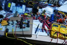
I worked in the advanced research lab for the last 14 years of my career at Motorola, mostly building EVB's and Proof Of Concept prototypes of ideas or potential new designs. It's still my first big step after a simulation says that something MIGHT work. Often it's a hand wired mess on as piece of perf board. Sometimes I'll commit to a PC board layout if it's a simple design, it has a high probability of success, or I need more than one of them.
I'm doing a layout of a high powered version of this output stage now, because I need to figure out how many of them I need to wire together to make 500 watts.
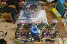
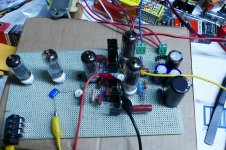
Here are some pictures of the same circuit squeezing 20 watts out of a pair of 50C5 radio tubes. I decided to take things in the smaller direction to test the new driver / phase inverter idea for the big push pull amp. This little guy passed the "run it at full power overnight" test with no ill effects, so I will eventually fill the remaining empty space on the perf board with a guitar preamp and this will become a little guitar amp. All of the tube heaters are wired in series and the whole thing runs from a Triad N-68X isolation transformer.
I recommend making a POC or other test design any time the risk of failure is not trivial......This is often the case when big voltages and expensive OPT's are connected together. I bought 200 guitar amp quality OPT's cheap about 20 years ago when I was making guitar amps. I still have a few, and use them whenever things might not turn out well. There is one on this 50C5 amp. About 15 years ago I set one on fire (flaming SVT style) when my load resistor went open as I passed through 150 watts on 750 volts of B+ headed toward 200 watts. The previously mentioned plate feedback resistor to ground arc almost blew another one last year, but I have successfully demagnetized it well enough to use for testing. It still has higher distortion than a fresh one.
I will probably try the two toroids in series trick with a pair of Antek 4TK400's that I got years ago before we figured out that they were made wrong and they were discontinued. If these work at low power they will be used for the first recent attempt at 500 watts. I don't want my fire breathing HP power supply to eat an irreplaceable Plitron OPT.
Ciss can become too high with three in parallel?
Ciss is not a big deal in a follower since the source follows the gate so that these two electrodes are nearly at the same potential all the time. Crss (gate to drain) capacitance is the critical spec on a follower, and these run about 30 pF each. You need a driver that will see about 100 pF most of the time. Not too hard, but 12AX7's need not apply.
Attachments
Fires in my career
I've had a few, but of a different nature. One of the first half decent jobs I had while still a high school student was at the DeHavilland Aircraft factory at Downsview near Toronto. So in Summer of 1948 before I turned 16 I worked in the paint shop. One night on overtime we were cleaning out one of the PBYs going thru the system, refitted for sub patrol, looking for Russians. The paint thinner we were using reached beyond the critical level so when a light fell & glass broke there was quite a thump & a lot of heat. I was in the compartment ahead of the observation bubble, I got out thru the bubble onto a stand beside the aircraft, my clothes were on fire. So I was the guest of a hospital for a while. Worst part was getting the bandages off, my skin had healed right into the gauze. Don't want to do that again.
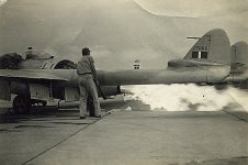
Four years later for the same company I went to Chatham AFB in New Brunswick. There was a DH Vampire which had fire damage on the electrical wiring in front of the jet engine. My job, replace the wiring. Took about a month & after a couple of tries the engine did start. This was an early jet engine based on Frank Whittle's original. There was often starting problems, a group of us would push the tail assembly down to drain the excess fuel if the engine didn't start. But could never get it all out so when there was ignition a good flame shot out the tail pipe. But that was normal.
More fires later, two in very large 3-phse transformers, the kind that leaves on a railway flat car.😱
I've had a few, but of a different nature. One of the first half decent jobs I had while still a high school student was at the DeHavilland Aircraft factory at Downsview near Toronto. So in Summer of 1948 before I turned 16 I worked in the paint shop. One night on overtime we were cleaning out one of the PBYs going thru the system, refitted for sub patrol, looking for Russians. The paint thinner we were using reached beyond the critical level so when a light fell & glass broke there was quite a thump & a lot of heat. I was in the compartment ahead of the observation bubble, I got out thru the bubble onto a stand beside the aircraft, my clothes were on fire. So I was the guest of a hospital for a while. Worst part was getting the bandages off, my skin had healed right into the gauze. Don't want to do that again.
Four years later for the same company I went to Chatham AFB in New Brunswick. There was a DH Vampire which had fire damage on the electrical wiring in front of the jet engine. My job, replace the wiring. Took about a month & after a couple of tries the engine did start. This was an early jet engine based on Frank Whittle's original. There was often starting problems, a group of us would push the tail assembly down to drain the excess fuel if the engine didn't start. But could never get it all out so when there was ignition a good flame shot out the tail pipe. But that was normal.
More fires later, two in very large 3-phse transformers, the kind that leaves on a railway flat car.😱
Attachments

- Home
- Amplifiers
- Tubes / Valves
- 450W bass amp: a sextet of GU50s with shunt¤t feedback