Spent some time yesterday at the Klipsch Museum in Hope, Arkansas. Very fun and laidback place, highly recommended if you're a DIYer; original Voigts, giant RCA theater speakers, Armstrong's original FM tuner, etc. and of course lots of historical Klipsch stuff.
I think Paul would have agreed with you. He famously said, in the context of his very sensitive speakers, that what the world needs is a good 5 watt amplifier. And he liked everything loud - artillery, trains, aircraft, and music.
All good fortune,
Chris
I think Paul would have agreed with you. He famously said, in the context of his very sensitive speakers, that what the world needs is a good 5 watt amplifier. And he liked everything loud - artillery, trains, aircraft, and music.
All good fortune,
Chris
I still have a hard time to understand the final schematics which you are trying to describe across multiple pages in this thread. Where to place that OA2 tube etc.
Let's focus on Mr. Gillespie's power supply. A full wave center tapped (FWCT) vacuum rectification scheme feeds a CLC, AKA Π section, filter. We will use a "full wave" voltage doubler (graphic previously provided), followed by a LC section. Think "extended" CLC filter, with the doubler stack in the 1st position.
") We will take advantage of SS diodes' ability to work into substantial capacitances. Use 2X of this 180 μF. part to form the doubler stack. Please notice that the effective capacitance in the 1st position is more than 2X the 40 μF. used with the vacuum rectifier. To tame the power on surge, a CL-140 inrush current limiter is placed in the line between the N-68X power transformer and the "center" of the doubler stack. Use this low cost Triad filter choke between the doubler stack and the reservoir capacitor. Use this part as the reservoir capacitor. Again, more than twice the capacitance of the vacuum rectified supply is being employed. There will be no shortage of energy storage.
We will take advantage of SS diodes' ability to work into substantial capacitances. Use 2X of this 180 μF. part to form the doubler stack. Please notice that the effective capacitance in the 1st position is more than 2X the 40 μF. used with the vacuum rectifier. To tame the power on surge, a CL-140 inrush current limiter is placed in the line between the N-68X power transformer and the "center" of the doubler stack. Use this low cost Triad filter choke between the doubler stack and the reservoir capacitor. Use this part as the reservoir capacitor. Again, more than twice the capacitance of the vacuum rectified supply is being employed. There will be no shortage of energy storage. 
We don't know the exact voltage of the B+ rail described. "Breadboard" the supply and determine its voltage value, under load. That number will control the resistance values employed in remainder of the power supply.
The reservoir cap. feeds the 0A2 current limiting resistor. That resistor feeds the anode of the gas discharge regulator. The cathode of the regulator tube is grounded. This 0.068 μF. noise suppression cap. is placed across the 0A2's electrodes. The screen grids of both O/P tubes are connected to the regulator's anode.
All that's left is a dropping resistor between the reservoir cap. and the decoupling cap. that feeds the 12AX7 anodes. The 20 μF. Mr. Gillespie used here strikes me as being quite adequate.
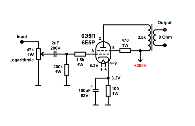
pcan, please confirm that I correctly captured your version of the Spud amp:
At Pout~3W THD is ~10%!
The maximum usable for listening is ~ 2W!
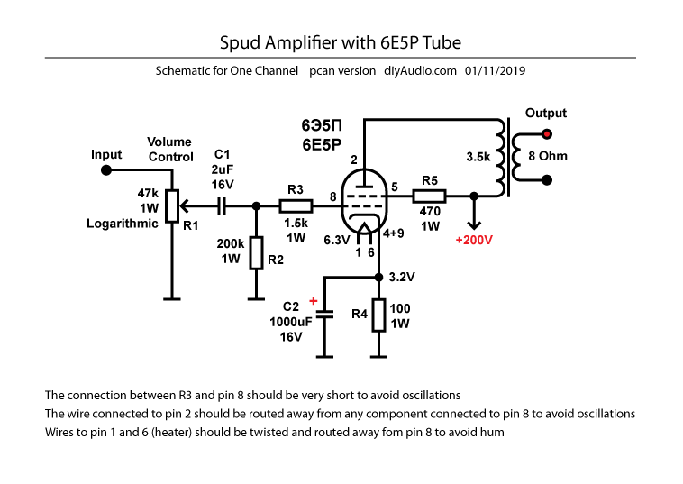
The schematic on post #82 is correct. The 2uF input film capacitor may be rated at far lower voltage, 16V would be ok. The cathode capacitor is not critical, can be increased up to 1000uF, and the voltage decreased to 16V. The resistor connected to pin 8 should have a very short lead between the resistor body and the tube socket; it is there to avoid oscillations. The wire connected to pin 2 should be routed away from any component connected to pin 8, again to avoid oscillations. Wires to pin 1 and 6 (heater) should be twisted togheter and routed away fom pin 8, to avoid hum.
Please be aware of the DC heater elevation done in my power supply, there is a +47V voltage superimposed to the AC filament supply. This is also a trick to avoid hum; the 150k and 47k resistors also drain the residual capacitor charge when the amplifier is turned off. The X2 film capacitor across the power trasformer primary is there to remove the bump you may hear when the amplifier is turned off. Use a good quality volume potentiometer, most cheap ones have bad tracking between sections and are noisy.
If your tubes are old stock with black oxidized pins, use #600 sandpaper or a knife edge to remove the oxide before inserting the tube in the socket. When you turn on the amplifier the first time, measure the b+ voltage and also the cathode voltage at pins 4+9; compare with the schematic values. I use a hook tip on my multimeter to have all the measurements done without touching anything. This tube has a inusually high gain and may oscillate at radio frequency if there is any positive feedback from output to input. This means that the output transformer wires should not be allowed to settle in a random position inside the chassis. Keep them away from the input.
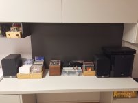
The attached picture is the current complete setup. The speakers are specified for 88dB sensitivity and 64Hz-22KHz frequency response. The HDCD player has a nominal output of 2Vpp. I get a normal listening volume when the potentiometer is at 9. The active subwoofer controls are set near the minumum because it only helps to fill the bottom frequency range (8'' driver). On most classical music I can turn it off and I barely notice the difference. I also have a passive sub but it does not work well with this amplifier without global feedback.
Please be aware of the DC heater elevation done in my power supply, there is a +47V voltage superimposed to the AC filament supply. This is also a trick to avoid hum; the 150k and 47k resistors also drain the residual capacitor charge when the amplifier is turned off. The X2 film capacitor across the power trasformer primary is there to remove the bump you may hear when the amplifier is turned off. Use a good quality volume potentiometer, most cheap ones have bad tracking between sections and are noisy.
If your tubes are old stock with black oxidized pins, use #600 sandpaper or a knife edge to remove the oxide before inserting the tube in the socket. When you turn on the amplifier the first time, measure the b+ voltage and also the cathode voltage at pins 4+9; compare with the schematic values. I use a hook tip on my multimeter to have all the measurements done without touching anything. This tube has a inusually high gain and may oscillate at radio frequency if there is any positive feedback from output to input. This means that the output transformer wires should not be allowed to settle in a random position inside the chassis. Keep them away from the input.
The attached picture is the current complete setup. The speakers are specified for 88dB sensitivity and 64Hz-22KHz frequency response. The HDCD player has a nominal output of 2Vpp. I get a normal listening volume when the potentiometer is at 9. The active subwoofer controls are set near the minumum because it only helps to fill the bottom frequency range (8'' driver). On most classical music I can turn it off and I barely notice the difference. I also have a passive sub but it does not work well with this amplifier without global feedback.
Attachments
Last edited:
Davorin,
Just a re-estimate of the spud amp power out:
Vk, Rk: 3.2V / 100 Ohms = 32mA (part of it is screen current, but most is plate current, so just call the total plate current 32mA for this discussion).
RL = 3500 Ohms
((I)squared)/2 x RL = Watts rms = 1.792 Watts rms
(with the plate current going all the way to zero, and clipping there).
Yes, there will be more than 2 x 32 mA on the high side of the current swing,
but the low current will already be at clipping (so a little more than 1.792 Watts, but at high(er) distortion).
Occasionally I forget to take the output transformer loss into account, but here is an example:
You start with 1.792 Watts from the tube, but then there is typically a 0.5 dB loss in the output transformer (89% of the input power), so you only get 1.597 Watts out (again, at clipping and high distortion).
Spud output: < ~ 1.6 Watts
For near-field listening at my computer desk, I typically use less than 1/4 Watt.
Last edited:
Would you please elaborate on the meaning of this? I do understand that headroom is important - espesially when listening to Not-heavily compressed recordings. I believe Liszt and Suppe are composers, but im very unclear about the full meaning.Eli said:"squashing" a 100+ player Liszt or Suppe "potboiler"
I find this thread very inspiring, and I hope that both the here-mentioned versions of the Spud and Magnavox amplifiers will get their owns threads with full scematics, as they each seem very thought out.
Last edited:
Liszt and Suppe wrote for large orchestras that included cymbals, big bass drums, and other percussion instruments. The sound can be loud/noisy and is (IMO) something like a vigorously boiling pot.
Franz Josef Haydn was the 1st great composer to employ a "battery" of cymbals, bass drum, and triangle, in his Symphony #100, nicknamed "Military". Haydn scored for the "battery" in the 2nd and 4th movements. Still, there's considerable difference between a late 18th Century public performance orchestra of (perhaps) 35 players and a mid to late 19th Century "Romantic" orchestra of over 100 players. Berlioz, Liszt, Suppe, and others can be great fun. However, it is my opinion that Haydn was a more accomplished composer. The Viennese Classicists: Haydn, Mozart, Beethoven, and Schubert are a brutal standard to be measured against.
Franz Josef Haydn was the 1st great composer to employ a "battery" of cymbals, bass drum, and triangle, in his Symphony #100, nicknamed "Military". Haydn scored for the "battery" in the 2nd and 4th movements. Still, there's considerable difference between a late 18th Century public performance orchestra of (perhaps) 35 players and a mid to late 19th Century "Romantic" orchestra of over 100 players. Berlioz, Liszt, Suppe, and others can be great fun. However, it is my opinion that Haydn was a more accomplished composer. The Viennese Classicists: Haydn, Mozart, Beethoven, and Schubert are a brutal standard to be measured against.
Member
Joined 2009
Paid Member
fyi - Hawthorn Audio had a popular spud amp. I posted the schematic of it here
Yukon Gold - a spud amp
Yukon Gold - a spud amp
Guerilla and Eli Duttman,
I think the small power amplifiers are just fine for: 1. Either with extremely efficient loudspeakers, 2. Or for near-field listening (close to the loudspeakers).
As to (2.) above, IF you could have been near-field listening (actually there with Liszt when he broke the frame on a Piano) your ears would have remembered the experience. I am not sure, but Liszt may have broken more than one Piano frame.
We all remember the piano, but who remembers the Forte part of the actual name, pianoforte. I think Liszt was capable of creating the Triple Forte.
By the way, a 90dB/Watt @ 1 meter speaker has 99.5 dB @ 1/3 meter with 1 Watt in; entirely possible with near field listening at the computer desk.
Last edited:
pcan, thanks a lot for very detailed instructions! Here is updated schematic with your notes:
Next I'll try to make the schematic for the power supply for the Magnavox type amp. Then we will see if we could have such thing as a free lunch and reuse that PS for Spud
Bigun, I like your compact design shown on the last page in that thread. How about noise, hum interference and all other stuff usually caused by the compact design? Thank you.
Then we will see if we could have such thing as a free lunch and reuse that PS for Spud
The "Spud" needs a 200 VDC B+ rail. The voltage doubler we've been discussing will come in around 300 VDC. A Maida style regulator should get that 300 down to 200, without creating a space heater.
Here is the first iteration of the power supply for the Magnavox type amp. There are some question marks which indicate that I have no idea about the value of the component, voltage or where the signal should go. Eli Dittman, please review and point me to the errors. Thank you!
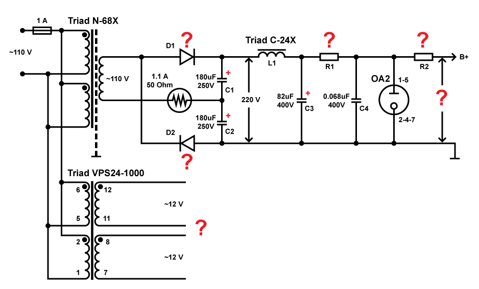
Here is the first iteration of the power supply for the Magnavox type amp. There are some question marks which indicate that I have no idea about the value of the component, voltage or where the signal should go. Eli Duttman, please review and point me to the errors. Thank you!
There's not much to fix, including an omission of mine. D1 & D2 are UF4007s. I forget to mention this snubber cap. that connects the junction of D1 & D2 to ground. Remember, each of the caps. in the doubler stack will charge up to the peak voltage of the N-68X's secondary {(VRMS)(21/2)} So, the voltage across the doubler stack is over 300 V., but inevitable losses are present. The junction of L1 & C3 is a key distribution point. The O/P tube anode supply (B+) comes directly from the L1/C3 junction. The junction also feeds R1 (the gas regulator current limiter). Take the O/P tube screen grid supply (B2+) from the anode of the 0A2. R2 is the 12AX7 anode supply (B3+) dropper and it connects to the L1/C3 junction, not the 0A2's anode. R2 in combination with a 20 μF. decoupling cap. feeds the 'X7 anodes.
Connect the secondaries of the VPS24-1000 in parallel by tying lug 8 to lug 12 and lug 7 to lug 11. That makes up to 2 A. of heater current available and 2X 6Π15Π O/P tubes plus a 12AX7 draw only 910 mA. We want the heater supply to be 12.6 VRMS -10%/+5%. If necessary, resistance can be added to the heater supply to get it into the desired range.
On my EL84 amplifier, I used the C-14x choke (6H 200mA). It may be OK for the spud, instead of the 10H choke. 1H (C-24X) is maybe a tad too low.
Accordingo to PSU designer 2 simulations, with the C-14X choke in place, the voltage at the node between L1, C3 and R1 with 100mA load will be 255V. It is the upper limit for the spud (I built it at 200V, a little increase on the power supply dropping resistor will solve this), and the lower limit for the Magnavox (you will get a little less power). I like to run 6,3V filaments in parallel, but if the filament transformer only has 12V windings, the 6e5P filaments could be wired in series at 12V.
Accordingo to PSU designer 2 simulations, with the C-14X choke in place, the voltage at the node between L1, C3 and R1 with 100mA load will be 255V. It is the upper limit for the spud (I built it at 200V, a little increase on the power supply dropping resistor will solve this), and the lower limit for the Magnavox (you will get a little less power). I like to run 6,3V filaments in parallel, but if the filament transformer only has 12V windings, the 6e5P filaments could be wired in series at 12V.
I like to run 6,3V filaments in parallel, but if the filament transformer only has 12V windings, the 6e5P filaments could be wired in series at 12V.
Wiring the 2X 6Π15Π heaters in series and wiring the resulting composite, in turn, in parallel with the ends of the CT 12AX7 heater is the plan. Connect the junction of the O/P tube heaters to pin 9 of the 'X7 socket. That "bus" can used as a point to ground the heaters and (possibly) bias the heaters off B+, for noise control purposes.
Here is the second iteration of the power supply:
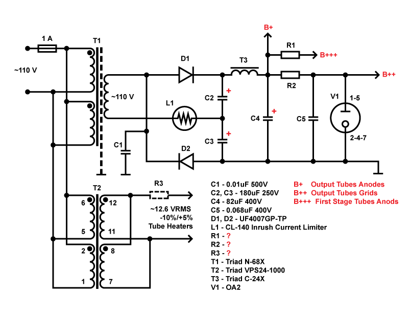
I'm not sure where to place that 20 uF cap. Is it also possible to define the values for resistors or it should be found by experimenting? What should be at least the starting value and wattage? Please let me know if anything else should be changed so that I would wrap up the PS and prepare the schematic for the amp itself if it differs from the original one.
I'm not sure where to place that 20 uF cap. Is it also possible to define the values for resistors or it should be found by experimenting? What should be at least the starting value and wattage? Please let me know if anything else should be changed so that I would wrap up the PS and prepare the schematic for the amp itself if it differs from the original one.
I'm not sure where to place that 20 uF cap. Is it also possible to define the values for resistors or it should be found by experimenting? What should be at least the starting value and wattage? Please let me know if anything else should be changed so that I would wrap up the PS and prepare the schematic for the amp itself if it differs from the original one.
The 20 μF. cap. goes between B+++ and ground. R1 and that cap. decouple B+++ from B+.
Yes, the ultimate resistance values are determined by experimentation. Ohm's Law calculations and computer simulations are of value. However, good old cut and try gets things done.
B++ is the feed for the O/P tubes screen grids (g2). There is only a single 1st stage tube, a 12AX7, that contains 2 triodes. The single 12AX7 is shared between the 2 channels.
C1 is a 2000 WVDC rated snubber part. Inductive spikes can present an unpleasant voltage surprise. Leave the AC ratings of caps., if any, for electric motor applications.
Let's use Mr. Gillespie's 29 July 2015 signal schematic as our point of departure. It contains a very important feature, the ability to adjust the O/P tube's control grid (g1) bias. Remember, O/P tube anode dissipation must be held within documented limits and manipulating the bias is exactly how that goal is reached.
Several changes to that signal schematic are already known to us. A 0.082 μF. film dielectric cap goes in the line from the I/P jack's center pin, to suppress infrasonic noise. The 12AX7's grid to ground resistance is 100 K, not 470 K. The 12AX7's grid stopper is 100 Ω, not 10 K. 6Π15Π-EB (6p15p-ev) O/P tubes will be employed, but future use of the 6BQ5/EL84 is not excluded. A 10 Kohm carbon composition stopper is used on the O/P tube's control grid (g1). The O/P tube's screen grid (g2) voltage is "150" V. (as required by the 6Π15Π), not 255 V. I state "150", as the exact voltage will depend on the 0A2 specimen acquired. Edcor O/P "iron" will be employed. The value of O/P tube anode B+ will be in the vicinity of 300 V. and the exact value will be determined experimentally.
A few more changes are to come, but they are not world shattering.
- Status
- This old topic is closed. If you want to reopen this topic, contact a moderator using the "Report Post" button.
- Home
- Amplifiers
- Tubes / Valves
- Need 3-5W tube amp