To get the starting vaules of the power supply resistors I use the PSU Designer II, free download from PSUD2 . Old software, works well up to Windows 7, on Windows 10 you need to do the standard compatibility tricks to get back the online help feature (but you probably don't need it).
On small amplifiers like this one, there is a way to save on power supply transformer space and costs. Instead of separate conventional insulation transformer and filament transformer, select a slightly oversized generic non-incapsulated toroidal 1:1 insulation transformer such as this one: Toroidal Transformer, 200VA, 2 x 115V ac | RS Components.
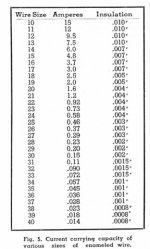
Any equivalent brand and type will do, they are commonly used on electrical installations and also are usually available from surplus. Get a small spool of enameled copper wire of suitable section (see attached table - 4A is a good target) and temporarily wound 10 spires around the core. This magnet wire is commonly sold by any electronic distributor, or you can reclaim it from a discarded transformer. Connect a power resistor to this temporary winding to simulate your load. Measure the resulting voltage across the resistor. Use a proportion to calculate the number of spires needed to get 6,3V, add one to compensate for the extra load you will apply to the regular HT winding. The number will be low; on the specific transformer I selected is 25 (if I correctly remember). Calculate the total lenght of the wire needed plus a few inches as spare. Cut two lenghts of this wire, and tightly wound them on the toroid, keeping the two wires parallel to each other. Kapton tape may be useful to keep the wire in place. Secure the ends of the windings to the toroid body: you now have a center tapped 12.6V extra winding on your transformer. This winding works below 50V and therefore does not compromise the safety certification of the transformer.
On small amplifiers like this one, there is a way to save on power supply transformer space and costs. Instead of separate conventional insulation transformer and filament transformer, select a slightly oversized generic non-incapsulated toroidal 1:1 insulation transformer such as this one: Toroidal Transformer, 200VA, 2 x 115V ac | RS Components.
Any equivalent brand and type will do, they are commonly used on electrical installations and also are usually available from surplus. Get a small spool of enameled copper wire of suitable section (see attached table - 4A is a good target) and temporarily wound 10 spires around the core. This magnet wire is commonly sold by any electronic distributor, or you can reclaim it from a discarded transformer. Connect a power resistor to this temporary winding to simulate your load. Measure the resulting voltage across the resistor. Use a proportion to calculate the number of spires needed to get 6,3V, add one to compensate for the extra load you will apply to the regular HT winding. The number will be low; on the specific transformer I selected is 25 (if I correctly remember). Calculate the total lenght of the wire needed plus a few inches as spare. Cut two lenghts of this wire, and tightly wound them on the toroid, keeping the two wires parallel to each other. Kapton tape may be useful to keep the wire in place. Secure the ends of the windings to the toroid body: you now have a center tapped 12.6V extra winding on your transformer. This winding works below 50V and therefore does not compromise the safety certification of the transformer.
Attachments
pcan, thank you for the alternative variant of the PS transformer! I'd like to avoid making manual transformer section. I did that long time back when I was a kid and remember that it was boring 🙂 Though this info will be useful for another more adventurous people.
Here is the semi-final version of the PS schematic:
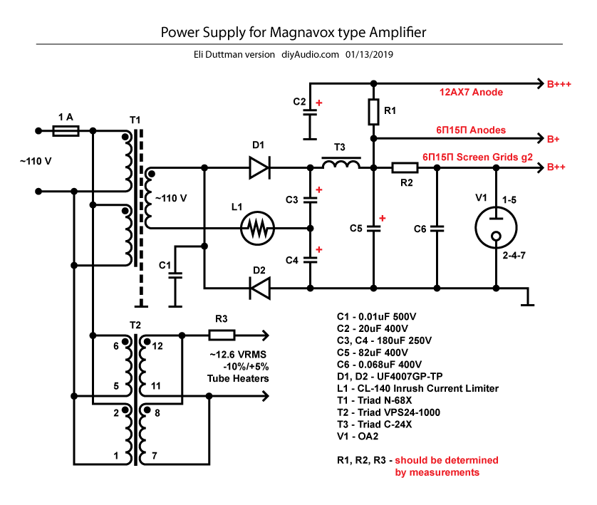
Eli Duttman, please check the schematic correctness and values/ratings of the components. What are the expected voltages and currents for B+, B++ and B+++ ? How do you usually find proper values for resistors? Do you use pot for that or just Ohm's Law? Thank you.
Here is the semi-final version of the PS schematic:
Eli Duttman, please check the schematic correctness and values/ratings of the components. What are the expected voltages and currents for B+, B++ and B+++ ? How do you usually find proper values for resistors? Do you use pot for that or just Ohm's Law? Thank you.
pcan, do you mean that if I would use choke CX-14X instead of CX-24X then PS could be used for Spun amp as well?
The C-14X choke has higher inductance and resistence compared to C-24x. According to the simulation, on the Magnavox amplifier it will drop B+ by 10V compared to C-24X, but it will lower the ripple. Power supply ripple is of minor concern on the Magnavox, because the G2 power supply is stabilized, and a extremely sensitive speaker is not needed. On my spud schematic, any ripple from the power supply becomes a faint hum on sensitive speakers. I solved this by using a 10H choke and oversized filter capacitors, but you have several options if you want a power supply that does work for both schematics. If hum will be a issue on the spud schematic, you can increase the power supply reservoir capacitor value, or you can modify the spud schematic by connecting the G2 to the OA2 stabilized supply, or you can use a higher inductance choke such as the C-14X. This part could be very well used also on the Magnavox, if you don't mind to lose a little bit of power due to the 10V extra drop in B+ and have a bigger part to mount in the chassis.
Eli Duttman, please check the schematic correctness and values/ratings of the components.
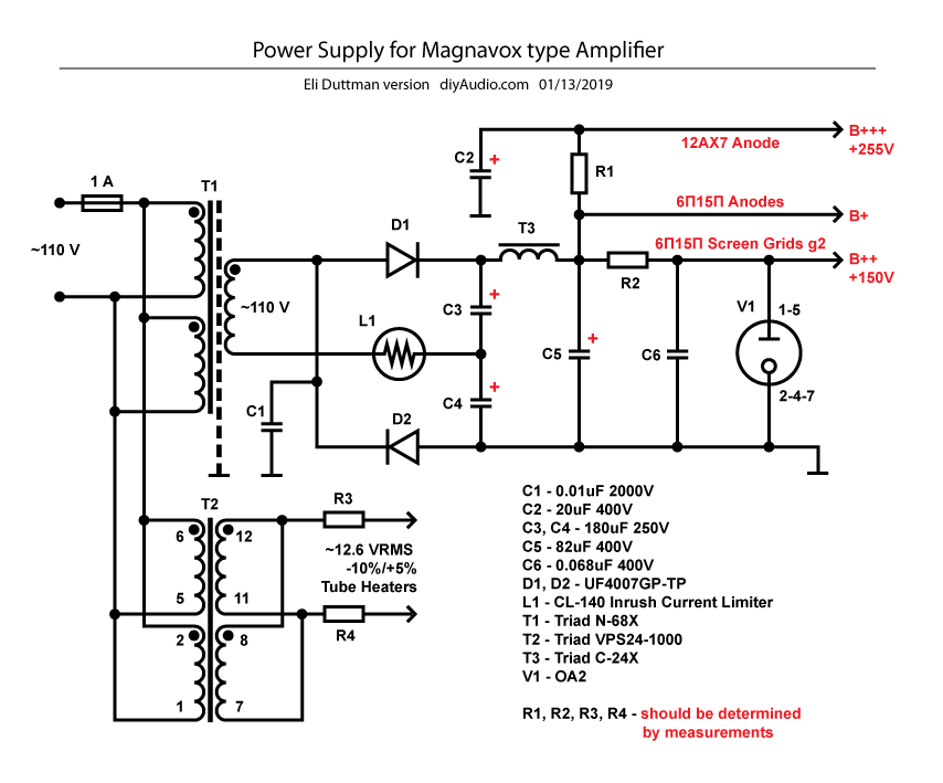
It's getting very close. C1 is 2000 WVDC, not 500. Symmetry matters. So, add a R3' to the lug 7/lug 11 "leg" of the heater supply. Distributing that resistance, if its presence becomes necessary, has the advantage of lowering wattage rating requirements. P = I2R.
How do you usually find proper values for resistors? Do you use pot for that or just Ohm's Law?
Both of the above and anything else you can come up with that helps. There are never enough wrenches in the toolbox.
What are the expected voltages and currents for B+, B++ and B+++ ?
B++ is "150", the nominal value for the 0A2. Get a "feel" for g2 current by looking at the previously linked 6Π15Π datasheet. A graph for g2 currents, with 170 V. applied, at various g1 potentials, is provided. With 150 V. applied the currents will be slightly smaller.
Mr. Gillespie provided the value for B+++. It's 255 V. The plate current for a 12AX7 section usually falls in the 0.9 to 1 mA. range. A plate current of 1.5 mA. is large, for the type.
The exact value of B+ is determined experimentally. Always keep 1 hand in a pocket, when taking measurements of tube setups. Potentially lethal voltages are present. Pain due to an error in technique, while unpleasant, is temporary. 😡 Death is permanent.
 The B+ number must be well known, but its absolute value is non-critical.
 O/P tube cathode current will be in the vicinity of 40 mA. "Breadboard" the doubler and LC reservoir section. Measure the supply voltage, without any load being present. "Plug" that number plus a 95 mA. draw into Ohm's Law, to get the value for a "dummy" load resistance. Unless a very costly ultra-high wattage part is used, only BRIEF measurement periods are permissible. Determine the working B+ rail voltage.
BTW, C-14X choke "pcan" mentioned is perfectly acceptable. Low ripple is good and the absolute B+ voltage, within reason, is non-critical.
Thank you! Here is the final schematic. Later on I'll add values for resistors and B+ voltage. It looks like the choke CX-14X is much bigger than CX-24X. So I'll keep the latter for now.
Last edited:
For the Magnavox amp schematic should I follow the original design or Mr.Gillespie's design?
While not an exact copy, we will use Mr. Gillespie's design as the starting point.
Several changes have already been mentioned.
There is one open question which I'd like to clarify. Is it common practice to use DC-DC converters for tube amps and feed them from low voltage switch PS? Are there any drawbacks of such approach like noise etc?
I'm just trying to minimize the number of PSs for the project. I need +5V 3A for Raspberry Pi micro-computer, DAC and touchscreen. +180V 30ma should feed IN-9 tubes for VU Meter. +3.3V 2A is required for stepper motor (if I'll go this route). For +3.3V and +180V I'm going to use DC-DC converters working from +5V. Therefore I'm just wondering about the same for the tube amp.
I'm just trying to minimize the number of PSs for the project. I need +5V 3A for Raspberry Pi micro-computer, DAC and touchscreen. +180V 30ma should feed IN-9 tubes for VU Meter. +3.3V 2A is required for stepper motor (if I'll go this route). For +3.3V and +180V I'm going to use DC-DC converters working from +5V. Therefore I'm just wondering about the same for the tube amp.
Eh... It's not really all that new of an idea (Berning was doing it decades ago) but it's still relatively rare. In some instances you may need to do a lot of PSU filtering to keep the HF hash out of the supply to the amplifier. Kodabmx does it relatively frequently, and could give you some advice on it, he seems to get along pretty well with it.
180 V./30 mA. is a fair bit of "juice". The current capability (presently "100" mA.) of the B+ supply could be increased and an additional "arm" (linear regulator?) added to the PSU, to provide 180 V.
The OP will have to weigh the pros and cons (noise, space, heat, ...) of the several options and make a decision.
The OP will have to weigh the pros and cons (noise, space, heat, ...) of the several options and make a decision.
rpi,
You need to calculate R2, not just dial it in. The 0A2 Needs at least 5 mA, and 30mA maximum. If you set the 0A2 for 17.5mA (middle of its operating range, and add the predicted screen currents of the output tube, you get the current that passes through R2.
B+ Volts - B++ Volts of 150V = the voltage drop in R2 Voltage Drop/(17.5mA + 2 screen currents) = R2 Ohms Be sure to use the current in Amp form, i.e. 0.0175 A.
But of course, you have to pre-calculate the B+ voltage. Either use a software program, or calculate it manually (don't know if you know how to do that).
Until you get the +150V set, you can not just measure the B+ in the amp, because if the screen is anything other than 150V, the plate current will vary accordingly.
You need to know the voltage of the B+ secondary, DCR of the B+ secondary, the DCR of L1 (what is L1? A transient limiter?), and the DCR of T3. Then know your desired plate currents of the output tubes, screen currents of the output tubes, and the plate currents of the 12AX7. Now, you can calculate the B+ voltage under load.
If the B+ secondary is 110Vrms, and a pure sine wave, under load there will be somewhat less than 311VDC at the input to T3 (T3 is a filter inductor, normally listed as L3).
Designing "by the seat of the pants" to use one power supply, and connect to another amplifier circuit, requires either some calculations, or requires some really lucky guesses.
By the way, if you have the B+ unloaded, it will raise to maximum, the filter caps have to stand that voltage. And if you then dial in R2, you could pass a lot more than 30mA through the 0A2 (and ruin it).
Be careful with C6. I know it is there to reduce the noise of the 0A2. The problem is you may have a relaxation oscillator (R2, C6, 0A2), especially before the output tubes warm up and draw screen current. In that case, you may need to remove C6.
Caution: You do not have any bleeder resistors on the B+. The power supply will drag down to about 150V, and stay there when you turn it off (especially if you do not have the amp tubes in the amp and filaments warmed up when you turn the amp off). The end voltage is unknown if only the amp tubes and 0A2 are the only drain when the amp is turned off. Wire a bleeder resistor across the B+. Safety First! You Effectively have about 200uF of capacitance on the power supply. Two 25k Ohm 5W resistors in series will drag the voltage from about 300V down to 100V in 10 seconds. After you turn the amp off, by the time you get the screws out, and the bottom cover off (20 seconds) the amp will be safe.
Last edited:
6A3sUMMER , thank you for the very detailed description for the measurement process. That's exactly what concerns me right now as I don't have this kind of experience. I'll try to follow all the guidelines given here.
So far I'm thinking to use one +5V 5A power supply for the digital part plus converters from +5V for stepper motor and IN-9 for VU Meter. The amp (analog part) will have its own PS discussed here. More likely because of space limitations either both PSs will be outside of enclosure or one of them.
So far I'm thinking to use one +5V 5A power supply for the digital part plus converters from +5V for stepper motor and IN-9 for VU Meter. The amp (analog part) will have its own PS discussed here. More likely because of space limitations either both PSs will be outside of enclosure or one of them.
rpi,
Which amp circuit are you using?
Where is a schematic of the amp, including tube types, resistor values, and original power supply that ran it, with B+ secondary voltage, etc.
What is the DCR of: your B+ secondary, the "L1", and T3 (L3)?
Trying to design a power supply for two completely different amplifiers complicates the circuit, and calculation of values.
I use DC-DC converters all the time. I power them from 12V. I don't do anything special to deal with "HF hash" except a standard RC filter usually. I've used a choke on rare occasions though. I also apparently don't know how to use multiquote...
6A3sUMMER, there are two main candidates for the amp - Spud and Magnavox type amp. I like the simplicity of the Spud. The only concern is its power - about 1.5W. The other candidate is Magnavox type amp. I'll try to come with schematic soon. It will be based on the version from Mr. Gillespie (you can find the schematic for it in this thread.) with some modifications from Mr. Eli Duttman.
Ideally I'd like to start from the simple one (Spud) and if it doesn't satisfy from the power point of view switch to the Magnavox and reuse PS and output transformers for both if possible. That was the plan. If it will need too many compromises then I'll focus only on Magnavox type amp.
You can find the PS schematic for the Magnavox type amp above. As I said if it's difficult to make one size fit all let's focus on Magnavox amp for now.
Last edited:
I use DC-DC converters all the time. I power them from 12V. I don't do anything special to deal with "HF hash" except a standard RC filter usually. I've used a choke on rare occasions though. I also apparently don't know how to use multiquote...
Let's take Magnavox type amp as an example. It needs 3 different DC voltages (plus one AC for heaters). Does it mean that there is the need in 3 different DC-DC converters in this case?
I've tried all my best merging Mr. Eli Duttman's changes to Mr.Gillespie's design. Please correct me if I made errors and please address the question marks. What is the wattage of the resistors? Thank you!
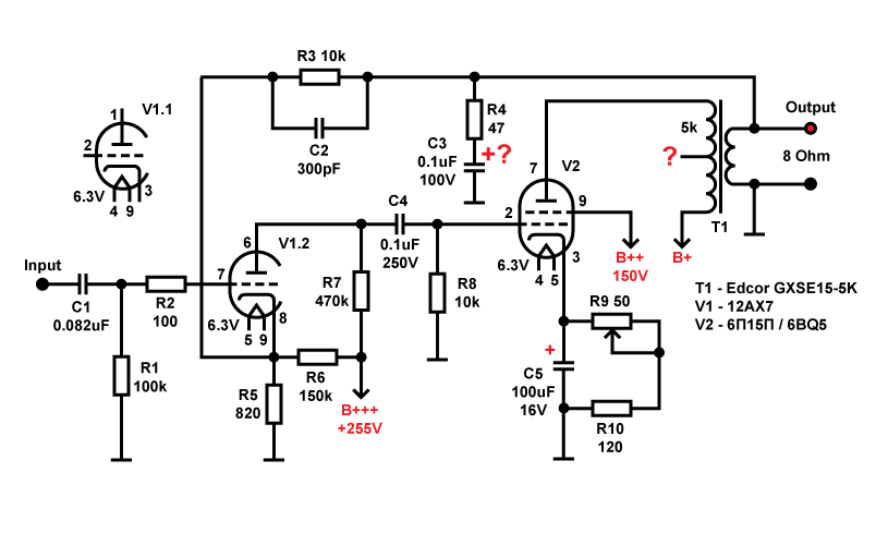
I've tried all my best merging Mr. Eli Duttman's changes to Mr.Gillespie's design. Please correct me if I made errors and please address the question marks. What is the wattage of the resistors? Thank you!
This is a full pentode mode amp. The ultra-linear (UL) tap on the O/P trafo's primary is unused. Thoroughly insulate the end of that wire and tuck it out of the way.
Whether or not the R4/C3 Zobel network is necessary has to be determined experimentally. That issue and the value of phase compensation cap. C2 are intimately associated with the properties of the specific O/P trafo being employed. We do not know those important properties. Do you own a signal generator and an oscilloscope? If you don't, brute force methodology can be employed.
R8 was, and should remain, 470 Kohms. An additional 10 Kohm carbon composition grid stopper, like R2, is connected to g1 of the O/P tube.
In general, 1/2 W. rated resistors are fine. However, it is necessary to look where substantial current is flowing to see if a more robust part is in order. R7 is carrying 'X7 plate current. Assume a 1 mA. plate current and the part dissipates 0.47 W. To ensure an adequate margin of safety, use a 2 W. rated part here. Current flows from B+++ to ground, via R6 and R5. A quick "crunch" suggests R6 dissipates approx. 0.43 W. Again, a 2 W. rated part is in order.
For an increased range of adjustment, make variable resistor R9 150 Ω. To simplify Ohm's Law calculations of O/P tube cathode current, make R10 100 Ω. To prevent trouble with deep bass phase shifts, make C5 680 μF. As it was blocked at the amp's I/P, infrasonic noise is not a matter of concern.
The 6Π15Π (6p15p) brings the suppressor grid (g3) out to the base. Show g3 in the schematic and its pin 1 connection to pin 3, the cathode. 6BQ5s, with their internally connected connected suppressor grids, work in sockets wired for the 6Π15Π.
Let's take Magnavox type amp as an example. It needs 3 different DC voltages (plus one AC for heaters). Does it mean that there is the need in 3 different DC-DC converters in this case?
I doubt it. If you can use one passive power supply, you should be able to just drop in a DC-DC board in place of the transformer/rectifiers. Wire the heaters for 2 tubes in series, parallel them, and run them off the 12V supply that powers the DC board.
- Status
- Not open for further replies.
- Home
- Amplifiers
- Tubes / Valves
- Need 3-5W tube amp