the 10R I have on hand is too long and covers the test points....
Ah, makes sense.
Is it possible to use Russian 6p3s-e (6П3С-Е) with those Baby Huey EL34 boards?
I am also interested to know but these are the differences,
6P3s---Tetrode but EL34 which is a pentode.
maximum anode V is 375 v in 6P3s vs 800v in el 34.
filament current in 6P is 900ma vs 1.5 amp in EL34
pin1 not connected in 6p and it is g3 in el 34.
My conclusion:
6p3s is not compatible with EL34 in this circuit.
Am I correct ??
I also noted that there are EL 34 and EL34 B.
I quote from an advert
EL34 tube has two kinds EL34A and EL34-B, EL34A is USES the control gate and acceleration (g2) grid structure,Belongs to a pentode. EL34-B are g1, g2 Accurate on the gate. Is a beam tetrode, such tubes are manufactured for moderate power amplifier. Also suitable for ultra-linear circuits.
Are both of these compatible?
I have never heard of an EL34 A and B. Could you post more details about the advertisement?
Interesting question about the 6p3s-e in the previous post.
Where did you get the 375 V for anode Max V on the 6p3s-e? I think that number may be for the 6p3s, which is closer to 6l6gb.
The 6p3s-e is quite different and close to 6L6gc. I can’t find a datasheet on it now, but I can tell you that I have been running those in my Eico ST87 for 3 -4 years now with great sound and without problem (the same set). I could check if you need a real life number, but the ST87 puts about 450 vdc across the EL34 (anode to cathode). The 6p3s-e requires more (negative) bias for the same anode current, and higher drive, but in the Eico ST87 they were a great match, and I think I prefer them to EL34s. My theory is that is the case because the Eico ST87 has higher than normal (for EL34) impedance transformers - if I remember right they are 6.6k ohm.
So, I think 6p3s-e tubes will work well in the BH EL34 set-up if you could bias it properly with your bias supply. You may need to provide -80V to the Mosfets to achieve that and swing enough voltage to drive the output to full power.
How will they sound in your BH EL34 amp? Since the 6L6 family appreciates higher loads than EL34, you may not like them as well as your EL34 if your tranformers are below 6k.
Last edited:
I have never heard of an EL34 A and B. Could you post more details about the advertisement
It is news for me too. It seems to be this ad.
Online Shop 4pcs use for Shuguang El34B EL34-B (el34,El34A) matched batch quad vacuume tubes | Aliexpress Mobile
Regards,
Last edited:
What tubes to try in Naby Huey EL34
Let’s wait for more information on the EL34b if it exists as more than marketing hype and why.
Back to the Russian 6p3s (without the -e). I believe that tube is very close to the 6l6gb spec. I want a BH 6p3s!
My octal BH (let’s not limit it to EL34) will be built so that I could throw 6p3s tubes at it. I will use a 6.6k output transformer and a 60 VAC bias transformer. HV supply around 350VDC depending on my storage closet.
Also would like to try some sweeptubes in it (with socket mods of course) to see how they do and sound. I have many EL500’s and would like to try them out. (Yes I know the EL500 has a top cap).
Reversing D5 means that you put + voltage on C10 instead of - If c10 is still working you are lucky. You probably damaged the current source transistors Q1 and 2 and possibly the LED. Does the LED light up when you have D5 connected properly?
I finally found time to get back to this - yes, C10 was cooked, replacing it and Q1 and Q2 made no difference so I probably managed to fry a few more transistors as well. I ended up replacing the whole board with one of the spares I bought, my desoldering skills are lousy, I always end up killing the board. All good now, hooked up on the bench and playing sounds very nicely. I still can't get enough -ve voltage to bias the KT88's down running them with a B+ of 450v, so they are running at 375v - I may have to get an additional little 65-70v transformer to do that.
Glad to hear you got up and running. Those thick boards are very hard to unsolder on the ground plane. I have had difficulty removing temporary terminals on the ground connections that were used for testing. I have -94 regulated for my bias voltage supply. I can adjust bias at the output grids to about -61 volts maximum. For KT 88s at 450v and 60 ma you need somewhere between 50 and 55 volts bias. You need to be careful to not exceed the capacitor ratings in the bias circuit on the board. The caps I used are rated at 100volts.
I have a regulated supply for hv set to 450v for el34. I am installing a switch so I can lower the HV for other tubes or plate currents I may want to try.
I am currently wiring up my chassis which is a big job with all the regulated supplies. I am getting there, may be done sometime next week. Just a hour or 2 now and then to work on it. I am looking forward to hearing it. When measuring distortion it seemed like the 2nd harmonic was dominant at lower levels, more so with the KT88 then the el34, perhaps because of the higher plate current I was running on the bigger tube.
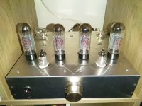
Hello! Here is my build, I have been enjoying lovely sound for some time now! Thanks a lot again Bandol, Prasi and everyone who has contributed to this amp.
I have a small issue with buzzing from only one channel, when the volume potentiometer is in the middle. The buzzing goes away when the volume is set very high or very low. Today I rewired all the signal path with shielded wire, trying to avoid any ground loops. It reduced overall hiss (or it might just be my mind after two hours messing with it), but it did nothing for the buzzing. I have also twisted all ac cables, and have soldered the heater wires directly under the sockets.
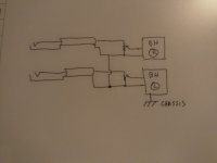
I have attached a drawing of my grounding, the buzzing channel is the R. Before changing to shielded, the R channel was also directly grounded to the chassis. The chassis is on another point connected to the mains earth.
The input connectors are also isolated from the chassis.
I would really appreciate any pointers on what to check!
Thanks!
Anestis
I have a small issue with buzzing from only one channel, when the volume potentiometer is in the middle. The buzzing goes away when the volume is set very high or very low. Today I rewired all the signal path with shielded wire, trying to avoid any ground loops. It reduced overall hiss (or it might just be my mind after two hours messing with it), but it did nothing for the buzzing. I have also twisted all ac cables, and have soldered the heater wires directly under the sockets.
I have attached a drawing of my grounding, the buzzing channel is the R. Before changing to shielded, the R channel was also directly grounded to the chassis. The chassis is on another point connected to the mains earth.
The input connectors are also isolated from the chassis.
I would really appreciate any pointers on what to check!
Thanks!
Anestis
Attachments
I have a bit of difficulty understanding the buck DC-DC supplies recommended. I bought some and received them without circuit or hook-up details. Could someone here enlighten me, please. What are the two adjusment pots needed for, shown on the right -one obviously output VDC, but the other?. How to hook up. Input is clear, but is it AC, or DC.
Pictures below:
Let me clarify my question. I believe the inputs are DCV between 6-30 and output between 6 and 24 DC, at upto 15 amps . Is this correct? What are the two different adjustments for?
Pictures below:
Let me clarify my question. I believe the inputs are DCV between 6-30 and output between 6 and 24 DC, at upto 15 amps . Is this correct? What are the two different adjustments for?
Attachments
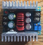
DC input is required. One pot ("CV") adjusts the output voltage, the other ("CC") adjusts output current. In practice you initially adjust the CC pot to the maximum current so it doesn't limit anything, then adjust the CV pot to get the voltage you want. Then with your normal expected load connected you can wind back the CC pot until the voltage just starts dropping (i.e. current limiting is overriding the voltage setpoint). Then wind the CC pot forward a turn or so. When turning on with cold heaters, the current will initially be limited and you get a slow rise in heater voltage. Once they are warmed up the voltage limit takes over.
Perfect! Just the info I needed. Thanks so much.
Another set of questions that I should have included earlier.
I shall, as I imagine others would, appreciate practical limits on these devices from empirical data. Does 3(?)-24 VDC outputs hold accross inputs of 6-30 VDC for the specified output for 20amp x output volts?
Another set of questions that I should have included earlier.
I shall, as I imagine others would, appreciate practical limits on these devices from empirical data. Does 3(?)-24 VDC outputs hold accross inputs of 6-30 VDC for the specified output for 20amp x output volts?
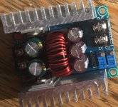
I haven't really experimented much with it. I bought a "DC 300W 20A CC CV" buck converter. I'm using a surplus 24V AC 50VA transformer rectified to 33V DC then dropping to 6.3V DC @ 4 amp load. Its a big voltage drop so efficiency not great, but heatsinks and inductor are barely warm. I bought the higher current module because I'm dubious about the advertised ratings.
Thanks for sharing you experience Mr. Tikiroo. This was very helpful. I believe the efficiecy of the conversion is >90%, so you are not loosing much energy in your conversion as evidenced by the cool heatsinks and inductor.
I shall do some experiments for my application in the near future, but your information will get me to my situation much faster.
"DC 300W 20A CC CV" buck converter
These devices seem to be really useful in enabling the using of cheap “odd voltage” tubes. My plan is to use 16gk6 tubes in stead of expensive 7189s.
Any experience to report.
Brian, how are things coming along?
I am very interested in you asessmemt of the Toirody transformers before I take the Plunge for output transformers. Any regrets. Like you I have a slew of suitable power transformers.
I shall do some experiments for my application in the near future, but your information will get me to my situation much faster.
"DC 300W 20A CC CV" buck converter
These devices seem to be really useful in enabling the using of cheap “odd voltage” tubes. My plan is to use 16gk6 tubes in stead of expensive 7189s.
Any experience to report.
I have a regulated supply for hv set to 450v for el34. I am installing a switch so I can lower the HV for other tubes or plate currents I may want to try.
I am currently wiring up my chassis which is a big job with all the regulated supplies. I am getting there, may be done sometime next week. Just a hour or 2 now and then to work on it. I am looking forward to hearing it. When measuring distortion it seemed like the 2nd harmonic was dominant at lower levels, more so with the KT88 then the el34, perhaps because of the higher plate current I was running on the bigger tube.
Brian, how are things coming along?
I am very interested in you asessmemt of the Toirody transformers before I take the Plunge for output transformers. Any regrets. Like you I have a slew of suitable power transformers.
Thinking about AC heating the tubes and how some have experienced or expressed concerns about hum. I think very hard to accomplish this with a PCB and tight layout.
Seems to me that the traces could be cut at the sockets, to isolate the heater pins from the traces, and the heater circuit wired with twisted pair and floated at some distance from the PCB. Shielded or perhaps even not, I think AC heating is very possible with satisfactory results this way.
Can anyone confirm that the -ve supply which biases the output stage through the SS driver comes up before the main B supply?. Looks as though they would 'come up together' and a 30 second delay to the main B supply might be a welcome addition, would also give the heaters time to stabilize.
HK
Last edited:
Brian, how are things coming along?
I am very interested in you asessmemt of the Toirody transformers before I take the Plunge for output transformers. Any regrets. Like you I have a slew of suitable power transformers.
Hi Francois
The BH is nearly complete electrically but I still need to add some of the wood trim and a box to cover the voltage regulators which are on top of the chassis. I have some cherry and purple heart wood I wanted to use but a plan hasn’t gelled yet. I’ve been busy with lots of other stuff including a new pair of speakers that arrived yesterday.
From an objective point of view the Toroidy OT have excellent performance. The bandwidth is wide, going out to over 100khz and below 10hz as well as having low resistance windings for low loss. I have not listened to the BH yet but right as it sits now it should be operational for el34 use. I just have to wire a switch or 2 to allow for changing thee meter range for KT88 and to allow a couple of B+ options. Chassis was built from a scrapped industrial computer box. I’ll try to post some pics later. They need to be resized first.
- Home
- Amplifiers
- Tubes / Valves
- EL34 Baby Huey Amplifier